Higman Chris Gasification (Газификация угля)
Подождите немного. Документ загружается.

270
Gasification
7.3.3 Advanced Cycles
Options for Improving the Joule Cycle
Although the CC cycle already has a high efficiency, it has the disadvantage that
two cycles are involved and much of the elegance of the simple Joule cycle is lost.
In relation to this it is interesting to explore whether the Joule cycle cannot be
improved in a similar way as the Rankine cycle has been improved over time.
Although both the Rankine cycle and the Joule cycle have made use of the benefits
of higher pressure ratios and higher temperatures, little has been done in the Joule
cycle to make use of features such as reheat and heat recuperation to improve the
cycle efficiency.
Cycles can be made more efficient by preheating the medium of the cycle (water
in case of the Rankine cycle, and air in case of the Joule cycle) with low level heat
that comes available during the cycle. In the Rankine cycle this is, for example,
accomplished by using extraction steam from the expansion turbine to preheat the
boiler feed water. In the Joule cycle such preheat is only possible in gas turbines
with a low-pressure ratio of 7-10 where the exhaust gas of the turbine has a higher
temperature than the exhaust air from the compressor. In that case the sensible heat
in the exhaust gas from the turbine may be used to preheat the air leaving the
compressor in a so-called recuperator. In more advanced industrial turbines and
aero-derivative turbines with pressure ratios of 15 and higher, the turbine and the
compressor have about the same outlet temperature, which makes recuperation
impossible. This is a serious disadvantage of more advanced gas turbines and is due
to the fact that virtually all gas turbine compressors feature adiabatic rather than
isothermal compression. The same reason limits the use of reheat in gas turbine
cycles. The very high pressures of 70–200 bar, which would be necessary for a real-
istic reheat cycle, prohibit the use of adiabatic compression.
Figure 7-19.
Figure 7-19.Figure 7-19.
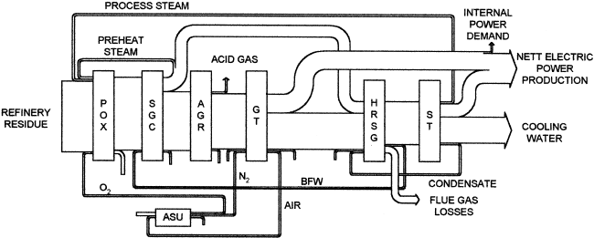
Figure 7-19. Sankey Diagram of a Residue-Based IGCC

Applications
271
More Isothermal Compression
The advantage of isothermal compression is not only that it makes reheat and
recuperation possible but also that it requires less energy than adiabatic compression,
as is illustrated by the following formulae for the isothermal and adiabatic compres-
sion of an ideal gas:
Isothermal
Adiabatic
where
E
is the energy in J/mol,
R
is the universal gas constant of 8.314 J/mol.K,
k
is
the isentropic exponent C
p
/C
v
of the isobaric heat capacity divided by the isochoric
heat capacity,
T
in
is the inlet temperature of the compressor in K, and
p
high
/
p
low
is the
pressure ratio of the compressor.
Taking air of 300 K, for which
k
is about 1.4 and a pressure ratio of 10, it is easily
shown that for this case adiabatic compression requires 1.41 times the energy of iso-
thermal compression. One should not be surprised by this large difference, as it must
be kept in mind that the energy for heating of the gas during compression is coming
from shaft power that otherwise could have generated power or electricity. This
heating is thus equivalent to electric resistance heating! In case of isothermal com-
pression the air will be heated with additional fuel in the combustor, but there the
heating takes place with virtually 100% efficiency, whereas via the shaft the heating
takes place with an efficiency of about 40% based on fuel.
Many attempts have been made over the years to accomplish a more isothermal
compression. The most obvious solution is to split the compressor in various parts
and to apply indirect intercooling between the various stages. Although this will
lower the energy required for compression, it has the disadvantage that the compressor
is split up in various parts and that the heat exchangers result in additional pressure
drop for the air flow.
An example of a more positive approach to a more isothermal compression is the
Sprint gas turbine that features a water spray injection between the two compressor
stages of a General Electric LM6000 aero-derivative gas turbine (McNeely 1998).
This so-called wet compression as a means to accomplish a more isothermal com-
pression has often been proposed in the past but was never applied (Milo AB 1936;
Brown, Boveri & Cie 1968; Beyrard 1966; Société Rateau 1952). The main purpose
of the water spray in the Sprint gas turbine is to increase the capacity of the turbine
for power generation, but at ambient temperatures above 5°C it also increases the
efficiency of the power plant.
ERT
in
p
high
p
low
------------
ln⋅=
ERT
in
k
k1–
-----------
p
high
p
low
------------
k1–
k
-----------
1–⋅⋅=
272
Gasification
Combinations of More Isothermal Compression and Recuperation
All major improvements in gas turbine–based cycles concern the use of a more
isothermal compression and recuperation. The highest efficiencies are achieved with
so-called humid air turbines (HAT) in combination with heat recuperation from the
turbine exhaust gases. The cycles involved are called HAT cycles. Two HAT cycles
will be discussed: the HAT cycle and the Tophat cycle.
The HAT Cycle
In the HAT cycle a flue gas heat recuperator replaces the heat-recovery steam gener-
ator (HRSG). In the recuperator the sensible heat in the hot exhaust gases leaving
the turbine are used to preheat humidified combustion air and water (Schipper
1993). The combustion turbine air compressor is also intercooled and cooled after
final compression (aftercooling). The heat recovered in these cooling steps preheats
additional water, and the hot water humidifies the pressurized combustion air in a
multistage, countercurrent saturator. The major disadvantage of this scheme is that
instead of a compressor and a turbine as in a normal gas turbine, many more pieces
of rotating equipment are required in the form of an additional compressor and
pumps. Moreover, large spray columns are required for humidifying the water to be
injected into the air, and finally, the heat in the hot gases leaving the turbine is used
for the low-temperature service of preheating and evaporating water. Various modi-
fications of the HAT cycle have been proposed, such as the cascaded HAT (CHAT)
cycle (Nabhamkin 1995), but all suffer from one or more of the disadvantages men-
tioned above. The only exception is the Tophat cycle discussed in the next section.
The Tophat Cycle
The reason why wet compression, that is humidifying the air during compression
inside the compressor, has found so little application is most likely due to the fact
that most atomizing devices available today can only produce water droplets with a
diameter of 30 µ or larger. Smaller droplets can be made, but this requires generally
complex or bulky equipment. An alternative for small droplets are spray towers as
used in HAT cycles, which result in additional pressure drops. This is a pity, as in
wet compression good use is made of the unique high heat of evaporation of water,
whereas this same quality is a disadvantage for the Rankine cycle.
Only recently an elegant and compact method has been proposed for making
small droplets. This has made it possible to inject an extremely large amount of
water into the atmospheric air entering the air compressor or in the compressor itself.
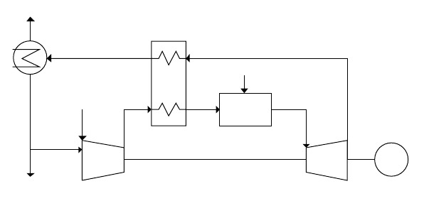
Flow Scheme
The flow scheme of the Tophat cycle is shown in Figure 7-20 (van der Burgt and
van Liere 1996). The water is injected in the air A entering the compressor in such
Applications
273
a way that the compressor does not suffer from a parasitic pressure drop. It is
injected in the form of very fine droplets of a mean diameter of about 1–3 µ. These
droplets, that can be made by combining flash evaporation with efficient atomizers
as in the “swirl flash technology” (van Paassen and van Liere 1980), are so small
that the droplets will (a) evaporate in the milliseconds available in the compressor,
(b) will not cause erosion problems, and (c) follow the path of the gas stream with-
out being centrifuged out. The humidified air B leaving the compressor at the required
pressure is essentially saturated with water. In a recuperator, the humidified air is
heated with the hot exhaust gases leaving the turbine to a temperature of, say, 50–
100°C below the turbine outlet temperature before being routed to the combustor,
where the hot air is used for the combustion of the fuel. The hot pressurized flue gas
C then enters the turbine. The exhaust gas D leaving the turbine preheats the humid-
ified air as well as the water used for humidifying the air and, if required, the fuel.
After leaving the recuperator the water in the exhaust gas is routed to a condenser, after
which the dry exhaust gas leaves via the stack. The condensate is partly recycled,
and the surplus is purged from the system.
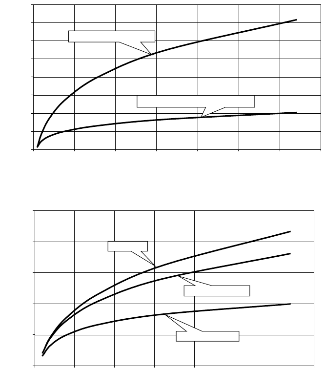
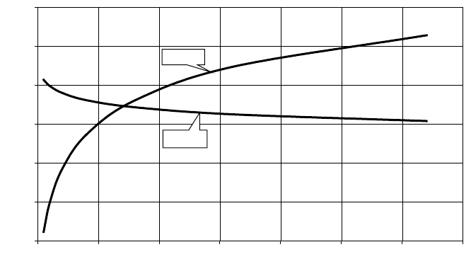
Quasi-Adiabatic Compression
The compression as proposed for the Tophat cycle is not completely isothermal but
quasi-isothermal. In practice it results in a compressor outlet temperature for the
humidified air, which varies from about 100 to 175°C for discharge pressures of 8 to
32 bar, respectively, when starting with ISO air (15°C and a moisture content of
1.19 mol%) and using injection water of 200 °C. This is clearly illustrated in Figure
7-21A (data for an isentropic efficiency of the compressor of 87%).
Quasi-isothermal compression hence requires less energy per unit (kmol/s)/ISO-air
than adiabatic compression. This advantage increases with the pressure ratio, as
illustrated in Figure 7-21B.
AIR
FUEL
FLUE GAS
COMPRESSOR
COMBUSTOR
GAS
TURBINE
GENERATOR
AB
C
D
WATER
NET WATER
PURGE
RECUPERATOR
CONDENSER
G
Figure 7-20.
Figure 7-20.Figure 7-20.
Figure 7-20. Tophat Cycle
274
Gasification
The greatest advantage of a more isothermal compression is that now it becomes
advantageous to have a recuperator in which the sensible heat in the gases leaving
the turbine are used to preheat the air leaving the compressor. This heat, which in a
combined cycle is used to drive an additional steam cycle, is now used in the more
efficient and less costly Joule cycle itself.
0
100
200
300
400
500
600
700
800
0 10203040506070
Pressure ratio
Temperature [°C]
Adiabatic compression
Quasi-isothermal compression
(A)
Figure 7-21.
Figure 7-21.Figure 7-21.
Figure 7-21. (A) Compressor Discharge Temperatures as Function of Compression
Ratio (B) Compression Energy for Adiabatic and Isothermal Compression
0
5
10
15
20
25
0 10203040506070
Pressure ratio
Compression energy [MW
e
per kmole/s isoair]
Adiabatic
Quasi-isothermal
Ideal isothermal
(B)
Applications
275
The Recuperator
Recuperators—or flue gas heated air pre-heaters—play an important part in some
synthesis gas technologies such as steam reforming but have not found favour in
connection with gas turbines, whether in IGCC or standard applications. This is a logical
outcome of the concentration on adiabatic compression and the fact that the outlet
temperatures of air compressor and gas turbine are too close for a recuperator to have
any important effect. Also the use of a recuperator with conventional quasi-isothermal
compression with the use intercoolers as used in process gas compressors does not
have any beneficial effect, since even if the heat removed via the intercoolers is used
for say boiler feedwater preheat, it transfers heat from the gas turbine cycle to the less
efficient steam cycle. This is different in the Tophat cycle since the heat is used to
increase the mass entering the gas turbine by evaporating water into the combustion air.
Arguments are sometimes raised against recuperators because of the poor heat
transfer and large surface area involved. These arguments are however generally
superficial. The steam superheater in the HRSG is also a gas-gas exchanger with
similar heat transfer coefficients as is the air preheater in a steam reformer and both
are successful components in their respective environments.
Furthermore, the construction of the headers and so on is much lighter than the
equivalent HRSG steam superheater, which reduces problems related to thermal shock.
Assuming that the Tophat stations will be started up and shut down as frequently as
the alternative of combined cycles, the point of thermal shock is not very relevant.
The reason is that the metal temperatures and temperature cycles are about the same
when the preheat temperature of the humidified air is restricted to the superheat
temperature of the steam in a CC.
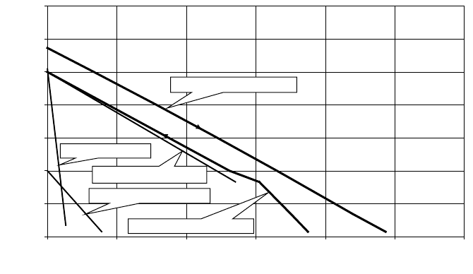
Moreover, the recuperator has a very smooth temperature profile in the steady
state. Because the heat exchange is restricted to the exchange of sensible heat (gas-
gas and gas-water) the enthalpy supply and demand lines are almost parallel, as is
illustrated in the typical example in Figure 7-22. In this example the humidified air
and the fuel gas are both preheated to 500°C, and the water used for evaporation
during compression is preheated to 200°C. As can be seen, there is hardly any pinch.
For the case in question, the hot exhaust gas, after having preheated the humidified
air, the natural gas, and the water, has a temperature of about 145°C.
The Water Cycle
The distillate quality water required for injection can be obtained by condensing the
water in the exhaust gas. This gas has then to be further cooled after it leaves the
recuperator. This can advantageously be accomplished in a two-stage direct contact
condenser. The first condensate, comprising 5–10% of the water present in the
exhaust gas, contains virtually all the solids contained in the combustion air and the
fuel that have acted as condensation nuclei. This water can be used as a purge in
order to avoid build-up of solid contaminants in the system. The pure condensate
from the second stage can then be used for humidifying the air.
276
Gasification
The use of indirectly cooled condensers does not look attractive because of the
large amount of inert gases in exhaust gas, as this results in very large heat exchange
surfaces and hence in costly equipment. Sometimes indirect cooling may be eco-
nomical though, for example, when the heat utilized in a combined heat and power
system involving, for example district heating or seawater distillation.
An important point is, of course, whether cooling water is available. On ships and
for offshore applications, this will never present a problem. In arid areas, air-cooling
or a cooling tower must be used. As all fuels contain hydrogen, there is always a net
production of water. In arid areas this is advantageously used for irrigation. In the
case of natural gas the mass of net water produced is about equal to the mass of the
fuel.
The Tophat Cycle Efficiency
The efficiency of the Tophat cycle is very dependent on the temperature difference
between the hot turbine exhaust gases entering the recuperator and the humidified
air leaving the recuperator. Typically for a 30°C decrease in the recuperator tem-
perature difference there will be an increase of about one percentage point on the
overall cycle efficiency.
Also, in the Tophat cycle the turbine inlet temperature is a factor in relation to
efficiency, although it should be realized that raising the turbine inlet temperature of
the turbine is not so important for the Tophat cycle as for a CC. The reason is that
because of higher inlet temperatures, both a high pressure ratio is required and the
temperature of the gases leaving the turbine is generally increased. Hotter exhaust
Figure 7-22.
Figure 7-22.Figure 7-22.
Figure 7-22. Typical Recuperator Enthalpy-Temperature Diagram
0
100
200
300
400
500
600
700
0 5 10 15 20 25 30
Enthalpy [MW
th
]
Temperature [°C]
Hot turbine effluent gas
Methane preheat
Injection water preheat
Total preheat required
Humidified air preheat
Applications
277
gases would lead to higher maximum temperatures in the recuperator and hence
imply the use of more expensive steels for this service. For this reason the maximum
preheat temperatures of the humidified air was limited to 500°C so as to keep the
maximum metal temperatures in virtually all cases to below 550°C. With these
restrictions there is not much effect in raising the inlet temperatures above 1300°C.
Station Efficiency and NO
x
Control
The biggest advantage regarding NO
x
control of the Tophat cycle is the fact that the
stoichiometric adiabatic flame temperatures (SAFTs) are so low. As is well known,
lower SAFTs result in lower NO
x
emissions. In the standard Joule cycle, higher sta-
tion efficiencies are obtained by increasing both the pressure ratio and the turbine
inlet temperatures, resulting in higher SAFTs. Using quasi-isothermal compression
as applied in the Tophat cycle generally leads to lower SAFTs for stations with a
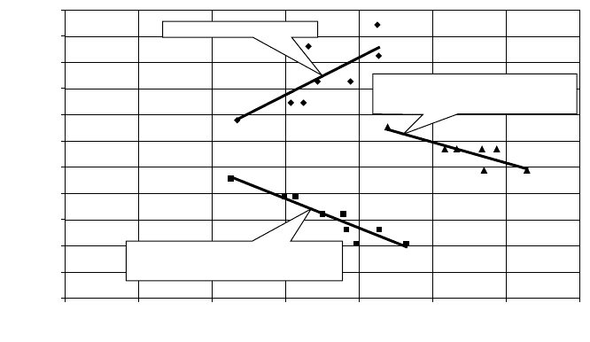
higher efficiency. This is clearly illustrated in Figure 7-23, where SAFTs are plotted
against station efficiencies for various cases: a Joule cycle, a Tophat cycle, and a
case where only quasi-isothermal compression (without recuperator) is used. The
reason for the low SAFTs of the quasi-isothermal compression cases is the low oxy-
gen content and the higher moisture content of the air (see Figure 7-24).
Applications
The high efficiency of the Tophat cycle of 60% or more makes it attractive for many
applications apart from as a replacement for combined cycle stations. The fast
Figure 7-23.
Figure 7-23.Figure 7-23.
Figure 7-23. Stoichiometric Adiabatic Flame Temperature as a Function of Station
Efficiency
1500
1600
1700
1800
1900
2000
2100
2200
2300
2400
2500
2600
0 10203040506070
Station efficiency [%]
Stoichiometric adiabatic flame temperature [°C]
Adiabatic compression
Quasi-isothermal compression
without recuperator
Quasi-isothermal compression
with preheat to 500°C
278
Gasification
start-up and the absence of a steam cycle make it attractive for many applications
where now open cycles are used. Examples include peak shaving, the use of gas tur-
bines in ships, offshore applications and liquid natural gas (LNG) plants, combined
heat and power schemes, and so on. The fact that Tophat cycles can be applied for
duties from, say, 500 kW onwards, means that they can even be considered for
trucks, locomotives, off-the-road vehicles, and mining equipment.
7.3.4 Flue Gas Treatment
The loss of efficiency involved in cycling of gas temperatures between hot and cold
parts of an IGCC have been pointed out on many occasions, and has been one of the
principle driving forces behind the so far unsuccessful attempts at a hot, or at least
warm, fuel gas clean-up. All current development efforts are based on performing
all the gas clean up on the fuel gas side of the gas turbine, not least because many of
these techniques are available from chemical applications. In this section we wish to
review the possibilities for reducing the fuel gas treatment to the absolute minimum
required by the gas turbine—which after all can operate on (sulfur-containing) fuel
oil—and perform the rest of the gas clean-up as flue gas treatment as in the rest of
the power industry.
IGCC Temperature Profiles
The ideal process for power generation from fossil fuels using combustion would
feature a steady rise followed by a steady drop in temperature and pressure in such a
0
5
10
15
20
25
30
0 10203040506070
Pressure ratio
Oxygen and water content [%mole]
Oxygen
Water
Figure 7-24.
Figure 7-24.Figure 7-24.
Figure 7-24. Oxygen and Water Content in Humidified Air
Applications
279
way that little heat and pressure energy is wasted. An open Joule cycle with heat
recuperation comes close to this ideal. A conventional IGCC is, however, very far
from this situation as, on the one hand, part of the gas stream has to be cooled to
−190°C in the ASU, and on the other hand, the gas leaving the high temperature
gasifier has to be cooled for desulfurization before being heated for the second time
in the gas turbine combustor.
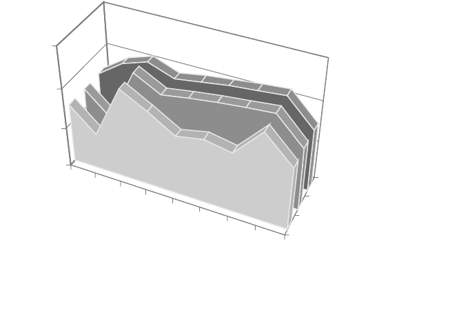
Figure 7-25 shows the temperature profile as encountered in a conventional IGCC
with fuel gas treatment (front profile) and in an IGCC with flue gas treatment for an
entrained-flow bed gasifier (middle profile). For comparison, an air-blown fluid-bed
gasifier with flue gas treatment is also shown (back profile). The temperature scale
is logarithmic, because it reflects somewhat better the thermodynamic repercussions
of the temperature cycling, since the ratios between the various temperatures are
more important than the absolute temperature differences.
Each kink in the diagram refers to the process unit mentioned along the abscissa.
Straight lines between kinks imply that the units in between are not present. It is
clear that flue gas treating gives a temperature pattern with fewer temperature
swings. It should be noted, however, that the cryogenic temperature applies only to
the air going to the ASU, whereas the high gas inlet temperature of the turbine
applies to a gas mass flow that is about a factor 5 higher.
Ambient
ASU
Gasifier
Filter
Water wash
HCN
/
COS removal
H
2
S
/
CO
2
removal
G.T. Inlet
Stack
Entrained-bed; flue gas treating
Entrained-bed; flue gas treating
Fluid-bed; flue gas treating
10
100
1000
10000
Temperature [K]
Process stages
Temperature profiles for gas in IGCCs
Figure 7-25.
Figure 7-25.Figure 7-25.
Figure 7-25. Temperature Profiles of a Various Types of IGCC Power Stations