Helena Ramos. Guidelines for design of small hydropower plants
Подождите немного. Документ загружается.


Hydraulic Transients and DynamicEffects
- 111 -
tE
KD
1
1425
c
+
=
(7.6a)
Should the pipe or tunnel thickness be very large and the elastic wave celerity
will be 1425 m/s. The pipe or tunnel elasticity will make to lower the celerity.
The pressure fluctuations related to these elastic waves will have, in a uniform
pipe of length L, the period 4L/c.
The basic waterhammer theory (ALMEIDA and KOELLE, 1992) teach us that
the maximum transient pressure variation ∆P
J
, due to a flow disturbance, follows
the Joukowsky formula:
Vcp
J
∆ρ±=∆ (7.7)
where ∆V is the flow velocity variation.
The negative signal is for upstream side of the flow control device and the
positive signal is for downstream side. Thus, for a flow velocity reduction ∆p>0
(the pressure will increase) at upstream side and will be ∆p<0 at downstream
side. For very long pipes with high friction headloss formula (7.7) for upstream
pressure variation need to be modified:
∆
∆
−
∆
∆
+∆=∆
3
J
o
J
o
J
*
J
H
H
12
1
H
H
1pp (7.8)
where ∆H
o
is the initial pipe head loss and ∆H
J
the head variation corresponding
to ∆p
J
(ALMEIDA, 1985).
The Joukowsky formula will be only valid for instantaneous or fast manoeuvres,
when the duration of flow change T
C
is less or equal to T
E
, the time of one round
trip of the first pressure elastic wave or the time for the elastic wave to propagate
from the source of the disturbance to the penstock intake, where it will be
reflected back with the same velocity, and returns to the disturbance source.
This situation can be avoided if T
C
is carefully chosen for normal operation
conditions in order that T
C
>>T
E
(slow manoeuvre). This could be easily obtained
by closing or opening the turbine flow controls device (nozzle or guide vane)
any safety valve or gate very slowly. For slow manoeuvres of complete flow
stoppage or start up), in real and normal design situations the approximate
relative head variation ∆H
M
/H
o
can be given by

Guidelines for design of SMALL HYDROPOWER PLANTS
- 112 -
C
W
T
o
M
T
T
K
H
H
=
∆
(7.9)
where K
T
is a factor that depends on the turbine type and operation (LEIN, 1965)
and T
W
is the hydraulic inertia time constant defined by
o
o
W
Hg
VL
T =
(7.10)
where
L = pipe length (m);
V
o
= initial or final flow velocity (m/s);
H
o
= reference net head (m).
For Pelton turbines K
T
will vary between 3.7 (closure) to 3.3 (opening) and for
Francis turbines K
T
will vary for both manoeuvres from 1.2 to 2.0 (being the
majored K
T
factor between 1.8 and 2.2). For certain theoretically conditions
K
T
=2.0 (Michaud’ formula mentioned in RAMOS, 1995).
A similar equation can be applied for the calculation of minimum heads or
pressures near the turbine gate. For pipe design, the transient maximum and
minimum heads need to be obtained along the axis profile (see Figure 5.18). For
a computer this information is easily obtained in each computational section. In
most of the approximate methods, a criteria for the head envelops need to be
followed: typically, for slow manoeuvres, a straight line is adopted for each
envelope, from the upstream or the downstream side of the turbine to the fixed
reservoir or tailrace levels, respectively.
Based on the two extreme enveloped lines, the maximum and minimum
pressures can be easily found by comparing those lines with the pipe or penstock
axis profile along terrain.
For both normal and abnormal turbine operations it is necessary to be very
careful with the minimum transient pressures downstream turbine runner (in the
draft tube) in order to avoid the water column separation, specially when there is
a long tailrace pressurised tunnel or pipe. An approximate criteria was proposed
by LEIN, 1965:
r
2
2
m
rm
Z
g2
V
HHd
p
−−∆−=
γ
(7.11)
where
Hd – downstream level (e.g. downstream river level);

Hydraulic Transients and DynamicEffects
- 113 -
∆H
m
– head variation giving the minimum transient head downstream the draft
tube;
V
2
– flow velocity at runner outlet;
Z
r
– turbine runner outlet section level;
p
rm
– minimum transient pressure at runner outlet section;
Water column separation will be avoided if p
rm
/γ > -6 m w.c.. This means that a
reaction type turbine runner elevation and the powerhouse elevation should be
fixed according, among other factors, to the downstream pressure transient
analysis.
7.3.3- Governing equations
The basic differential equations of the unsteady and transient pressure flows can
be written as follows (RAMOS, 1995):
()
()
UD
x
UF
t
U
=
∂
∂
+
∂
∂
(7.12)
where U, F(U) and D(U) are the following vectors:
() ()
−
=
=
=
QQ
Q
JgA
0
UD;
gAH
Q
gA
c
UF;
Q
H
U
2
2
(7.13)
in which x = distance along the canal bottom or the pipe axis (m); t = time (s); A
= cross-section flow area (m
2
); Q = discharge(m
3
/s; H = piezometric head (m); J
= slope of the energy grade line; g = gravity acceleration (m/s
2
); and c = elastic
wave celerity (m/s).
Equations (7.12) can be solved by computer codes based on numerical
techniques (e.g. method of characteristics) and on the specified boundary
conditions. Nowadays, the computer modelling is based on the discretisation of
the hydrosystem and the computational model will be composed by several
components (tube and non-tube elements) and nodes (ALMEIDA and KOELLE,
1992).
With these kind of models it is possible to simulate different operation conditions
and study the hydraulic behaviour of complex systems, including pipe networks
and all major hydro-mechanical equipment. Among these ones, the turbines are

Guidelines for design of SMALL HYDROPOWER PLANTS
- 114 -
the most important source of flow disturbances and their modelling is crucial for
a reliable computational model as a design aid tool.
The turbine modelling, especially in what concerns the reaction turbines (e.g.
Francis and Kaplan turbines), the turbine couples the upstream and downstream
sides of the pressurised hydraulic circuit. In these cases, the turbine modelling
implies the knowledge of the complete characteristic curves based on the
manufactures’ tests. These curves are very difficult to obtain for small
hydroplants.
In what concerns the action turbines (e.g. Pelton turbines), the pressure transients
will need to be considered along the upstream penstock. The disturbance source
will be the turbine nozzles, a special type valve that can control the flow by
changing the position of an internal part known as the needle. In this case, as in
all pressure transients induced by a flow control device placed downstream a
long pipe, it is very important to know the characteristic equation of such control
device, or the controlled flow for each nozzle (or valve) opening and each head
variation across the upstream and downstream sides or nodes of this specific
component.
Small hydropower schemes when installed in mountainous regions are typically
associated to long penstocks, in order to increase the available head, and to
action or impulse turbines (e.g. Pelton turbines).
With computational models it is possible to include the real nozzle
characteristics and the headloss variation along the penstock during the transient
regimes. The friction headloss can be characterised by the following pipe
parameter (RAMOS, 1995):
D
fL
g2V
H
F
2
p
=
∆
=
(7.14)
where ∆H is the flow total head loss;
g2V
2
is the kinetic head; f is Darcy-
Weisbach friction factor; L the pipe or penstock length; and D the pipe or
penstock diameter.
The computer simulations indicate that for high Fp values the flow control can
be very difficult to obtain, because the time duration of the physical manoeuvre
of the nozzle or valve differs very much of the real flow change duration T
C
. In
these cases, for a nozzle linear time closure, the discharge variation will be only
effective near the full closed position: the duration of the nozzle mechanical
Hydraulic Transients and DynamicEffects
- 115 -
manoeuvre is very different from the effective time of flow discharge variation
and a theoretically slow manoeuvre (T
C
>T
E
) can be, in fact, a fast one (T
C
<T
E
) as
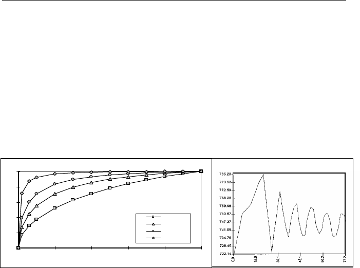
can be seen in Figure 7.4 (where Q
o
is the initial turbine discharge for full open
nozzle or turbine maximum discharge):
- the decrease of fL/D allows the discharge variation to be more
favourable;
- for large values of fL/D most of the discharge variation only occurs for
small values of nozzle opening, at the end of the nozzle manoeuvre.
Fig. 7.4- Discharge variation for different penstock characteristics and nozzle closures.
Head variation in the powerhouse for a typical manoeuvre (RAMOS, 1995).
The hydraulic conveyance circuit at upstream side of impulse turbines will be
influenced by the nozzle control system of the discharge variation imposed
through the closure law. This law and the hydraulic penstock characteristics will
be very important on the transient pressure analysis.
It is very important to note that it is
no sufficient to define the total manoeuvre
time duration without knowing the conveying system characteristics.
7.4- Overspeed dynamic effects
7.4.1- Overspeed runner control
During normal steady-state operating conditions the speed of a turbine is
constant, but it will rise quickly when the load of the turbine is rejected. During
the closure of the nozzle or the turbine guide vane, the speed of the turbine will
Pelton with 4 nozzles
Time (s)
H (m)
0.0
0.2
0.4
0.6
0.8
1.0
0.0 0.2 0.4 0.6 0.8 1.0
% opening
Q/Qo
fL/D=0,1
fL/D=5
fL/D=15
fL/D=100

Guidelines for design of SMALL HYDROPOWER PLANTS
- 116 -
rise to a maximum value that can not surpass the allowable one fixed by the
turbine manufacturer.
For impulse turbines the transients overspeed does not influence the pressure
along the hydraulic circuit. With reaction turbines the runner speed will change
the turbine discharge and the overspeed conditions will also influence the
hydraulic circuit (RAMOS, 1995). The transient overspeed can be a
waterhammer additional source, especially in what concerns the slow Francis
turbines (with small N
s
values). A complete computer analysis should be
performed based on the turbine characteristic equations, the complete hydraulic
equations (7.12) and the equation of the rotating masses of each unit:
dt
d
IBRBH
ω
=− (7.15)
in which BH is the transient hydraulic torque (N m), BR is the resistant or
electrical torque (N m), I is the rotating masses inertia (kg m
2
) and ω is the
angular rotating speed (rad/s).
An inertia machine time constant (or start-up time of rotating masses), T
m
, can be
defined based on equation (7.16):
3
o
2
o
2
m
10x
P3575
nWD
T
−
= (7.16)
where n
o
is the nominal runner speed (r.p.m.), P
o
the reference power or full load
turbine power (kW) and WD
2
= 4gI (N m
2
). T
m
has the order of magnitude of the
time for the unit to attain the speed n
o
when submitted to a linear increasing
hydraulic power from 0 to P
o
.
For impulse turbines, and especially in what concerns the Pelton type turbine, the
runner overspeed control can be obtained by a deflector that deviates the flow of
the runner. This means that a slower closure manoeuvre can be specified in order
to better control the transient pressures along the penstock. For reaction turbines
the simultaneous transient pressure and overspeed control is much more difficult
(RAMOS, 1995). In order to evaluate, in a preliminary analysis, what is the
turbine maximum relative overspeed after a full load rejection some approximate
formula based on equation (7.16) can be used (LEIN, 1965 and HADLEY,
1970):
Hydraulic Transients and DynamicEffects
- 117 -
• Lein formula
1
H
H
1
T
kT
1
n
n
o
C
m
C
o
−
∆
++=
∆
(7.17)
valid for ∆n < 0.5 n
o
. For Pelton turbines with jet deflectors, k=0.9, ∆H is the
upstream waterhammer or transient head variation due to the manoeuvre and T
C
is the time required by the deflector to change the flow direction, including the
dead time (T
C
≥ 1.5 s). For Francis turbines, k=0.8 and T
C
is the guide vane
closing time.
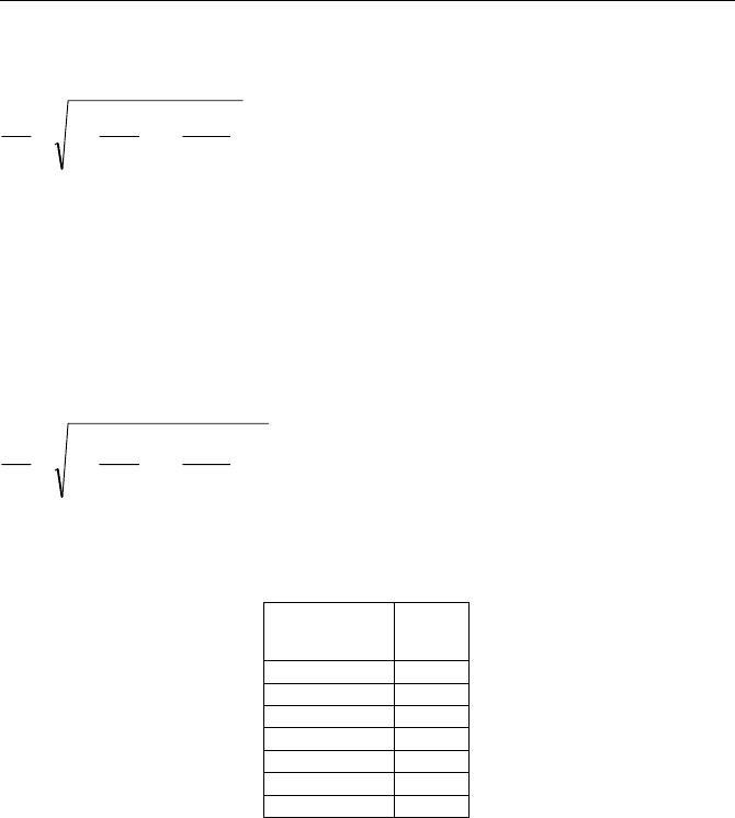
• Hadley formula
1
H
H
1
T
kT
1
n
n
2/3
o
C
m
C
o
−
∆
++=
∆
(7.18)
where k is now related to turbine characteristics as a function of the specific
speed N
s
, as indicated in the following table, and T
C
is the guide vane time of
closure:
Ns
(r.p.m.)
(kW, m)
k
76 0.98
134 0.96
286 0.84
381 0.77
573 0.66
672 0.61
763 0.57
Typically ∆n/n
o
should not exceed 0.6. For normal runner speed governing,
Hadley estimated that the following relationship between the minimum T
m
and
T
W
should be obeyed:
•
Pelton turbines – T
m
= 2.5 T
W
•
Francis and Kaplan turbines – T
m
= 3.0 T
W
The overspeed control and speed regulation stability in small hydroplants, during
normal operation with load demand changes, can be improved by increasing the
T
m
value through the WD
2
value (flywheel effect) or by decreasing T
W
value
(e.g. by inserting a surge tank or by selecting a larger penstock diameter). The

Guidelines for design of SMALL HYDROPOWER PLANTS
- 118 -
advanced electric speed-load regulators can now guarantee a better regulation
stability criteria.
Values of WD
2
and T
C
should be guaranteed by the turbine and generator
manufacturers and are agreed upon at design stage. Another effective way to
control the transient overspeed and pressure in hydrosystems equipped with
Francis turbines is to equip the spiral case with special pressure regulators or
water outlets which automatically open and discharge water (as a relief valve)
into the tailwater pool when guide vanes are closed too rapidly (synchronous
relief valves). If none of these procedures is enough to control the transient
overspeed and pressure then another special protection device should be
considered like a surge tank as a last resort.
In small hydropower plants connected to a large national electric grid, the
stability of speed regulation does not present any special problem, because the
grid has the capacity to stabilise any unstable behaviour.
In exceptional conditions the turbine runner can be forced to accelerate under the
hydraulic power until a maximum limit steady state speed or runaway
speed n
rw
is attained in 3 or 5 seconds. This maximum speed will depend on turbine Ns and
the head values and varies typically between 1.5 no (propeller turbines) and 2.0
no (Pelton turbines) to 3.5 no (Kaplan turbines) for design head Ho (see Table
7.2). For other values of H the runaway speed can be estimated as follows:
o
*
rw
*
rw
H
H
nn = (7.19)
According to the BUREAU OF RECLAMATION, 1976, the runaway speed can
be estimated by this empirical formula:
o
*
o
5/1
srw
H
H
nN63.0n =
(7.20)
where H
*
is the turbine head and H
o
is the net head for the best efficiency regime
and the regime speed n
o
.
Approximate formula must be used with care, as well as the estimation of the
WD
2
or I values for turbine and generator. For a detailed analysis and final
design stage, computer simulations should be made based on the real selected

Hydraulic Transients and DynamicEffects
- 119 -
machine characteristics in order to be possible to analyse the complete dynamic
behaviour and interaction between the system components.
7.4.2- Overspeed effects on turbine discharge
For impulse turbines (e.g. Pelton turbines) at a constant needle position, the flow
is independent of the runner speed. It is usual to operate the nozzle and the
deflector simultaneously (double regulation turbine) during a closure operation.
The deflector moves the jet away from the runner and the nozzle closure law has
the main influence in the discharge regulation and penstock flow variation. For
Francis turbines with low specific speed, the flow drops with the transient
overspeed a constant gate position. Conversely, for Francis turbines with high
specific speed and for Kaplan turbines the transient discharge tend to increase
(RAMOS, 1995).
On Table 7.2 and Figure 7.5 is shown the turbine discharge reduction for low
specific speed Francis turbines.
Table 7.2 – Runaway conditions for different types of turbines
Turbine N
s
Type
(m, kW)
Normal speed
n
o
(r.p.m.)
Runaway
speed
n
RW
/n
o
Runaway
discharge
Q
RW
/Q
o
Pelton 15-60 500-1500 1.8-2.0 -
Turgo 20-70 600-1000 2.0 -
Cross-flow 20-80 60-1000 1.8-2.0 -
Francis 80-300 500-1500 1.8-2.2 0.45-1.10
Kaplan 200-800 75-150 2.0-3.2 0.80-1.90
The flow across a runner, as former mentioned, is characterised by three types
of velocities: absolute velocity of the water V, with the direction imposed by the
guide vane blade, relative velocity W and tangential velocity C of the runner.
For uniform velocity distribution assumed at inlet (section 1) and outlet (section
2) of the runner and by application of Euler's theorem it enables obtaining the
equation, which relates the motor binary and the momentum moment between
these two sections:
()
222111
cosVrcosVrQBH α−αρ=
(7.21)
The output power in the turbine shaft is a result of multiplication the binary by
the angular speed ω.

Guidelines for design of SMALL HYDROPOWER PLANTS
- 120 -
ω⋅= BHP (7.22)
where
BH is the hydraulic torque and P the output power.
It yields in the following equation, after some transformations (RAMOS, 1995),
nB
n
AQ +
η
= (7.23)
with
β
+
απ
π
=
β
+
απ
π
=
22o2o
2
22o2o
2
o
tanA
1
tanrb2
1
60
r2
Band
tanA
1
tanrb2
1
r2
gH60
A
(7.24)
that gives a relation for turbine discharge depending upon the rotational speed
value and the characteristic of the runner.
The subscript
o denotes outlet from the wicket gate, 1 and 2 denote,
respectively, inlet to and outlet from the runner,
b
o
is the runner height (or free-
area), r is the radial distance, α is the angle that the velocity vector (V) makes
with the rotational velocity (C), β is the angle that runner blades makes with the
C direction and A
2
is the exit flow cross-section area.
Looking to this equation, the discharge regulation can be obtained by variation
of b
o
, α
o
or β
2
. The b
o
variation is not easy to obtain, because this parameter is
a fixed characteristic of a runner (related to the height of the runner). Thus, for a
constant rotational speed, the discharge variation can be obtained by the
following procedures:
1 - variation of α
o
;
2 - simultaneous variation of α
o
and β
2
;
3 - variation of β
2
.