Helena Ramos. Guidelines for design of small hydropower plants
Подождите немного. Документ загружается.

____________________ Small Hydraulic Turbines
- 91 -
s
s
N
Q
24.287.1H +=
(e.g. Hs )m2
≈
;
Q = turbine rated flow;
∆H
T
= total head losses in the hydraulic circuit.
and the turbine output capacity by
o
HQP ηγ=
(6.9)
In order to avoid turbines with low efficiency or bad designed characteristics it is
convenient to adopt N
s
according to manufacturer data information (or by
available literature) based, normally, on the net head and results of turbines
already tested.
The nozzle can have different open/close positions and it can be defined by a
displacement X (of the needle). When the nozzle is completely closed X is null.
β
α
2
2
db
d
X
Fig. 6.9 – Scheme of a Pelton nozzle.
N
eedle
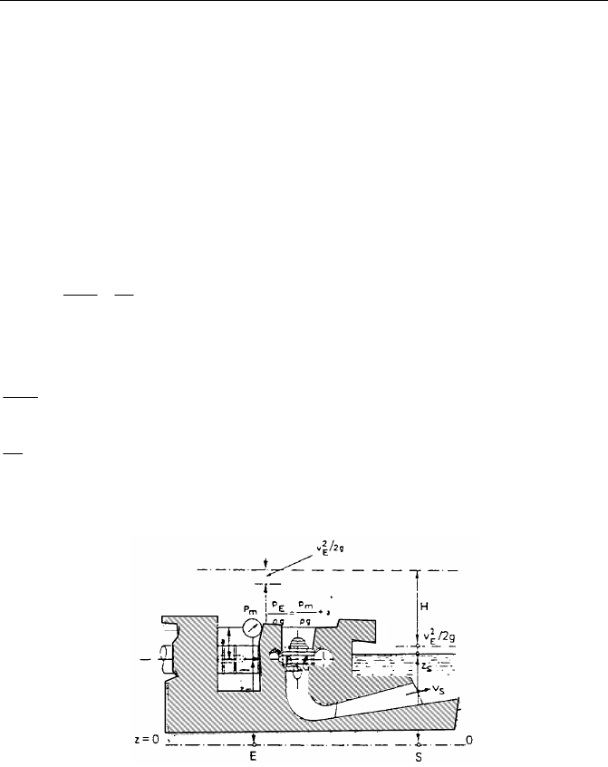
Ho
N
nozzle
Fig. 6.9 - Definition of the net head for a Pelton with one nozzle.
Guidelines for design of SMALL HYDROPOWER PLANTS
- 92 -
According to experimental tests (VIVIER, 1966 and MATAIX, 1975) the
discharge coefficient can be considered constant (except for very small open
degrees) and the discharge will be proportional to the free section of the nozzle.
Before the simulation of nozzle manoeuvres is necessary to calculate the initial
conditions (steady state) and the nozzle diameter. Based on the maximum
discharge and the free cross section defined by:
2.1
D
X
gH2CSQ
X
2
2sen
XDsenS
N
onoz
2
N
θ
=
=
α
−απ=
(6.10)
for each nozzle it yields a diameter given by the following equation
o
noz
N
H
Q
KD
α
= (6.11)
where
Q
noz
= maximum discharge of each nozzle;
θ = the open degree of the nozzle (θ = 1 completely open; θ = 0 completely
closed);
C = discharge coefficient (
≈
0.97- VIVIER, 1966 and MATAIX, 1975);
S = flow cross section of the nozzle;
K
α
= coefficient that depends upon the angle α of the conical needle end (e.g.
θ = 1 K
α
= 0.5445).
For constructive proposes, according to SIERVO and LUGARESI, 1978, the
external diameter D
2
and the diameter related to the centreline of the blades D
1
are
n
gH2K60
D
ou
1
π
=
(6.12)
(
)
N,s12
N0137.0028.1DD += (6.13)
and the blade dimensions are a function of nozzle diameter (D
N
)
____________________ Small Hydraulic Turbines
- 93 -
N,s
N,s1
N
N796.174.250
ND
D
−
=
(6.14)
02.1
N2
96.0
N1
D23.3HandD20.3H == (6.15)
where
N,su
N0039.05445.0K −= is the periphery speed coefficient;
N
P
H
n
N
4/5
o
N,s
= is the specific speed for each nozzle (N = number of nozzles);
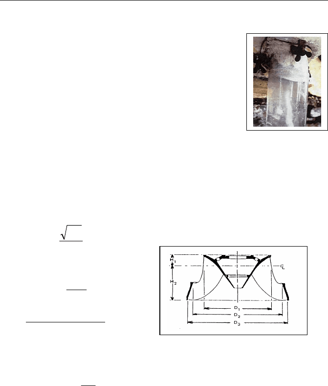
Fig. 6.10 – A typical Pelton runner
(adapted from SIERVO and LUGARESI, 1978).
Theoretically the choice falls on the greater specific speed turbine solution,
because it corresponds to smaller dimensions. However, on the one hand it must
be based on economic assessment, that includes civil works and equipment costs,
on the other hand the mechanical disposition of the group, maximum peripheral
speed of the rotor, and the minimum dimension for powerhouse, could help to
find the best choice. It is important to be aware that turbines with greater specific
speed lead a smaller runner diameter. However, for Pelton turbines the number
of nozzles can constrain powerhouse dimensions.
The dimensions of a Pelton turbine casing depend on the outlet diameter D
2
of
the wheel, where L gives the horizontal size of the casing. For prismatic casings
this value has been assumed equal to the average diameter of the circle inscribed
and circumscribed on the casing.
2
D06.278.0L += (6.16)
H
1
H
2
D
2
D
1
Guidelines for design of SMALL HYDROPOWER PLANTS
- 94 -
The distance G between the wheel centreline and the top of the casing and the
other dimensions for casing and for spiral case are defined by
2
D376.0196.0G +=
L70.043.0E
L7.0219.0D
L68.0362.0C
L694.0595.0B
L37.028.1I
L513.062.0H
L71.009.1F
+=
+−=
+=
+=
+=
+=
+=
Fig 6.11 – Casing dimensions (adapted from
SIERVO and LUGARESI, 1978).
•
Reaction turbines
Any reaction turbine is composed by the following elements:
Spiral case - with decreasing cross section to downward direction to
transform the pressure energy into kinetic one.
Wicket gate (or guide vane) - guides the inlet of the flow into the runner,
delivers it uniformly and control the turbine discharge.
Runner - radial or axial with or without movable blades.
Draft tube - pipe with increasing cross section to downward direction.
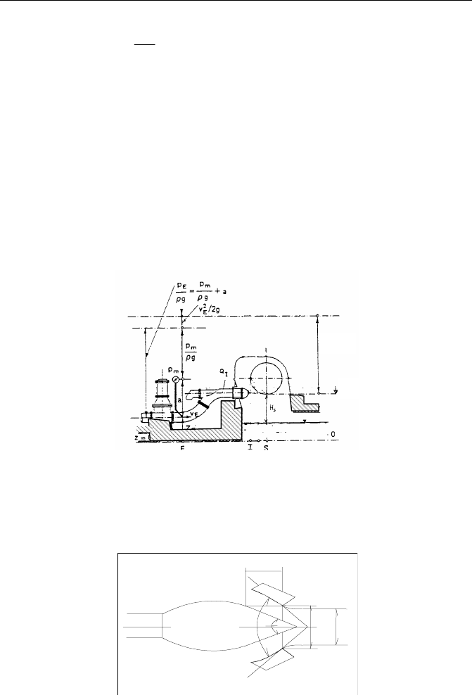
For reaction turbines, the flow is totally pressurised and the net head is defined
by
HNNH
riverreso
∆−−=
(6.18)
(6.17)
____________________ Small Hydraulic Turbines
- 95 -
and the rotor speed is similarly calculated as for impulse turbines. The estimation
of specific speed is obtained from manufacturer data as a function of head
(see 6.2)
Defined the turbine speed, the next step consists in calculation the runner
position in order to avoid cavitation. The admissible suction head (h
smax
) is
defined by the difference between the characteristic runner section and the
tailrace level. When the suction head is negative, the turbine operates in “back-
pressure”.
o
vatm
maxs
H
tp
h σ−
γ
−
γ
= (6.19)
where
γ
atm
p
= barometric local head (m);
γ
v
t
= vapour pressure (m);
σ = dynamic depression coefficient or Thoma coefficient;
H
o
= neat head (m).
Fig. 6.12 - Definition of the net head for a reaction turbine.
The barometric head depends on the local altitude and the vapour pressure from
the local temperature (Table 6.1).

Guidelines for design of SMALL HYDROPOWER PLANTS
- 96 -
Table 6.1 - Barometric head and vapour pressure
Altitude
(m)
γ
atm
p
(m)
Temperature
(ºC)
γ
v
t
(m)
0 10.35 5 0.089
500 9.75 10 0.125
1000 9.18 15 0.174
1500 8.64 20 0.239
2000 8.12 25 0.324
(adapted from Almeida, 1995)
Thoma coefficient (
σ ) gives the susceptibility to the cavitation occurrence of a
reaction turbine. This parameter depends upon N
s
. Several curves have been
proposed beeing one of them presented by Bureau of Reclamation, 1976 for
reaction turbines with vertical shaft:
38652
N
64.1
s
=σ (6.20)
with N
s
in (m, kW)
Fig. 6.13 – Shematic representation of suction turbine head (h
s
).
Out of normal operating conditions favour the cavitation phenomena
occurrence. As a result of cavitation development, the performance of the
turbine will be affected, since efficiency, appearance of vibrations and noise or
blades erosion:
____________________ Small Hydraulic Turbines
- 97 -
•
whenever exists a discontinuity of the flow;
•
the surface of a blade with different stages of
vortex development: initially by separating zones,
after by bulb formation and consequent rupture
that provokes vibrations and serious noise;
•
vortex band cavitation at the inlet of a draft tube
during partial load operating conditions, especially
for Francis, inducing periodical pressure
fluctuation, noise and hard vibrations in the
turbine.
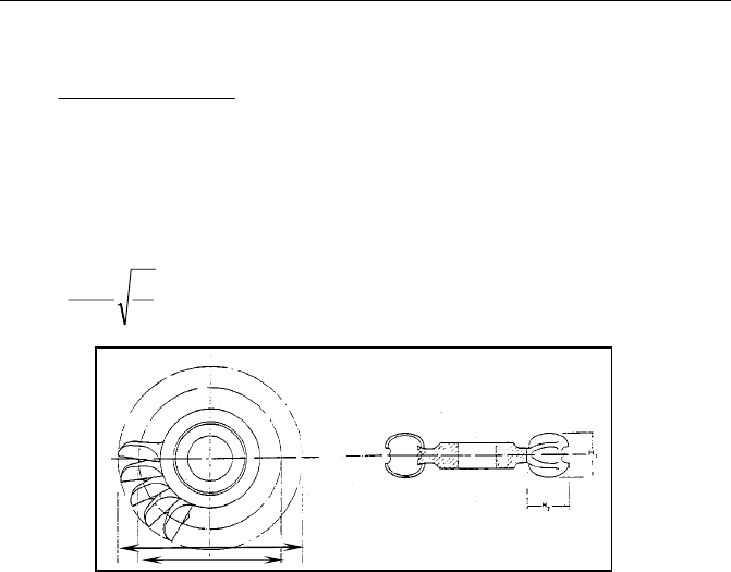
In order to predict turbine dimensions and the necessary excavation for the
powerhouse in an early phase of design, SIERVO and LEVA, 1976 present a
practical formula based on several parameters:
n
H
K5.84D
o
u3
=
s
3
u
N10x5.231.0K
−
+=
+=
s
31
N
5.94
4.0DD
s
3
2
N00038.096.0
D
D
+
=
()
s31
N00025.0094.0DH += Fig. 6.15 – Reaction turbine runner
(adapted from SIERVO and LUGARESI, 1976).
+−=
s
32
N
42
05.0DH
(6.21)
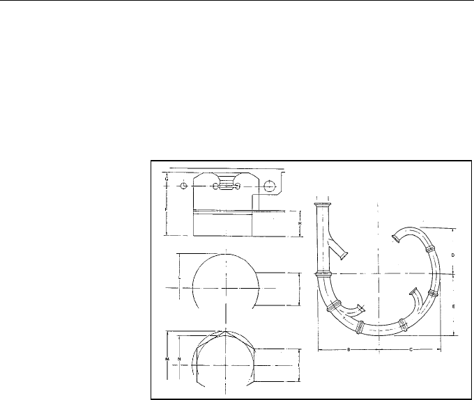
In the same way, the steel spiral case and the draft tube dimensions are estimated
by the following relationships (SIERVO and LUGARESI, 1976):
Fig 6.14 – Vortex in the draft
tube of an experimental
facility (at
LNEC, RAMOS, 1995).

Guidelines for design of SMALL HYDROPOWER PLANTS
- 98 -
- Francis turbine - Kaplan turbine
+=
+=
−=
s
3
s
3
s
3
N
25.49
32.1DC
N
8.54
1.1DB
N
56.19
2.1DA
()
()
s
4
M
s
4
M
2.0
sM
N10x24.346.1DC
N10x79.326.1DB
N40.0DA
−
−
+=
+=
=
+=
s
3
N
8.48
5.1DD
(
)
s
4
M
N10x74.559.1DD
−
+=
+=
s
3
N
6.63
98.0DE
(
)
s
4
M
N10x71.221.1DE
−
+=
+=
s
3
N
4.131
1DF
+=
s
M
N
17.72
45.1DF
+=
s
3
N
5.96
89.0DG
+=
s
M
N
63.41
29.1DG
+=
s
3
N
75.81
79.0DH
+=
s
M
N
86.31
13.1DH
(
)
s
4
3
N10x5.61.0DI
−
+=
−=
s
M
N
80.31
45.0DI
(
)
s
4
3
N10x9.488.0DL
−
+=
(
)
s
4
M
N10x7.874.0DL
−
+=
(
)
s
5
3
N10x5.160.0DM
−
+=
(
)
s
3
M
N10x2.106.2/DM
−
−=
+=
s
3
N
5.203
54.1DN
(
)
s
6
M
N10x14.20.2DN
−
−=
+=
s
3
N
7.140
83.0DO
(
)
s
5
M
N10x67.14.1DO
−
−=
(
)
s
4
3
N10x6.537.1DP
−
−=
−=
s
M
N
35.16
26.1DP

____________________ Small Hydraulic Turbines
- 99 -
+=
s
3
N
6.22
58.0DQ
−=
s
M
N
40.18
66.0DQ
()
s3
N0013.06.1DR −=
(
)
s
5
M
N10x98.725.1DR
−
−=
()
ss
N25.028.9/NS +−=
+=
s
M
N
51.201
26.4DS
(
)
s
4
3
N10x9.150.1DT
−
+=
(
)
s
4
M
N10x12.520.1DT
−
+=
(
)
s
4
3
N10x751.0DU
−
−=
+=
s
3
N
7.53
10.1DV
+=
s
3
N
8.33
63.2DZ
+=
s
M
N
66.102
58.2DZ
(6.56)
A) B)
Fig 6.34 – Spiral case dimensions (A) and draft tube dimensions (B)
(adapted from SIERVO and LUGARESI, 1978).
D
3,M

Guidelines for design of SMALL HYDROPOWER PLANTS
- 100 -
Through these interpolation functions the dimension of Francis and Kaplan
turbines can be characterised, allowing a better estimate of economic costs for
powerhouses and the definition of the relative position of each component.