Heard D.E. (editor) Analytical Techniques for Atmospheric Measurement
Подождите немного. Документ загружается.


Table 9.5 Actinic-flux spectroradiometers used in atmospheric field studies
Reference Inlet Optic
a
Spectrometer Detector
b
Wavelength range (nm) Bandwidth (nm) Measur. time Platform
Hofzumahaus
et al. (1999,
2002)
24 sr
c
Quartz Double
monochromator
Bentham DTM300
PMT 280–420 1 80–90 s Ground + Aircraft
Shetter and
Müller (1999)
24 sr
d
Quartz Double
monochromator
CVI 112
PMT 280–420 1 28 s Ground + Aircraft
Schmitt (1999) 2 sr Quartz Spectrograph
Carl-Zeiss
PDA 285–700
e
∼ 2 < 5 s Ground
f
Webb et al.
(2002b)
2 sr Quartz Double
monochromator
Bentham DTM300
PMT 290–500 0.5–1 – Ground
g
Eckstein et al.
(2003)
4 sr Teflon Spectrograph
Jobin-Yvon Cp200
CCD 300–600
e
1.8–2.8 30–60 s Ground
Jäkel et al.
(2005)
2 sr
dh
Quartz Spectrograph
Carl-Zeiss
PDA 305–700
e
2.5 < 1 s Aircraft
a
Optical diffusers with isotropic sensitivity; the field-of-view is 2 sr (hemispherical) or 4 sr (spherical).
b
PMT, photomultiplier tube; PDA, photodiode array; CCD charge-coupled device.
c
Airborne version uses one double-monochromator with two 2 sr optics for zenith and nadir view.
d
Airborne version uses two separate 2 sr spectroradiometers for zenith and nadir view.
e
Instrumental stray light reduces the accuracy of the actinic-flux measurements below 305 nm.
f
Commercial instrument, used by various research groups (e.g., Kanaya et al., 2003; Edwards and Monks, 2003).
g
Spectroradiometers equipped with actinic-flux sensing and irradiance-sensing inlet optics.
h
Zenith and nadir viewing inlet-optics are horizontally stabilised by active control.

Measurement of Photolysis Frequencies in the Atmosphere 439
When the radiation spectrum is recorded, the photon flux is measured in narrow
spectral intervals that are centred at discrete equidistant wavelengths
i
. The step size
of the wavelength grid is usually set equal to , which is chosen to be equal to or less
than the spectral bandwidth of the dispersing spectrometer (see Appendix A.3). Both
bandwidth and step size must be sufficiently small to resolve spectral variations of the
solar spectrum to allow an accurate determination of photolysis frequencies.
In practice, the calculation of j-values following equation 9.12 is performed as a
summation
j =
i
i
i
F
i
(9.29)
Here, F
i
,
i
and
i
denote average values of the quantities over the interval
at wavelength
i
(see also annotations on F
i
in Appendix A.3). Data for the cross
sections and quantum yields, which are functions of wavelength, temperature and possibly
pressure, can be taken from the literature (see Section 9.8.4).
9.4.2 Spectroradiometers for actinic-flux measurements
The general outline of a scanning spectroradiometer for the measurement of actinic flux
(e.g. Hofzumahaus et al., 1999; Shetter & Müller, 1999; Webb et al., 2002b) is illustrated
in Figure 9.17. In this example, the actinic radiation is collected by a hemispheric receiver
optic that is connected to the entrance slit of a spectrometer by an optical quartz-fibre
bundle. The application of the flexible light guide serves two purposes.
1. It allows to set up the spectrometer in a weather-protected, temperature-controlled
environment (laboratory container, aircraft cabin, etc.) while the inlet optic is mounted
outside, pointing into the sky.
2. In order to enhance light transmission, the fibres in the bundle can be arranged to
match one end to the round cross section of the receiver optic and the other end to
the rectangular shape of the spectrometer entrance.
Scanning spectroradiometers are generally based on double-monochromators with
diffraction gratings turning synchronously with additive dispersion and are usually
scanned from 280 to 420 nm for coverage of the most relevant photolysis frequencies.
Compared to a single monochromator, the double-monochromator set-up provides
double spectral resolution (i.e. half the spectral bandwidth) and several orders of
magnitude lower levels of instrumental stray light. These two properties are particularly
important for the accurate measurement of solar radiation at wavelengths below 320 nm,
where the spectral photon flux changes dramatically over many orders of magnitude (see
Figure 9.6).
At the exit of the double-monochromator, the selected radiation
i
is detected
by a photomultiplier tube (PMT), which needs a high voltage supply for operation. The
PMT output signal, a photocurrent, is further amplified and converted into a voltage
which is then digitized by an analogue–digital converter and recorded by a computer.
The large dynamic range of possible photon fluxes requires good linearity of the detection
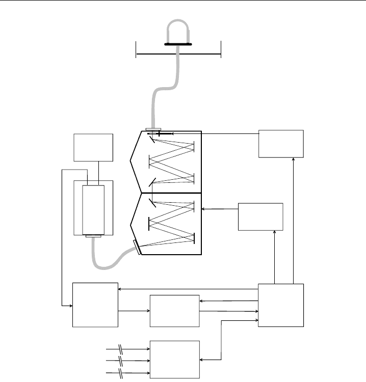
440 Analytical Techniques for Atmospheric Measurement
Diffuser
Optical fibre
bundle (10
m)
DM
FW
HV
PMT
AMP
ADC
PC
DL
Auxiliary
data
Optical fibre
SMD
Shadow ring
FWD
Figure 9.17 Schematic diagram of a scanning spectroradiometer for actinic-flux measurements: DM,
double monochromator; HV, high-voltage supply; AMP, current-to-voltage amplifier; ADC, analogue–
digital converter; PC, personal computer; DL, data logger; SMD, stepping motor drive; FWD, filter wheel
driver; FW, filter wheel with optical shutter (from Hofzumahaus et al., 1999, used with permission of
Optical Society of America).
system for at least six decades. This is generally accomplished by selected PMTs with very
low dark current and multiple-stage current-to-voltage amplifiers.
A computer collects the measured data and controls the wavelength setting
i
of the
double-monochromator. Some spectrometers, like the one in Figure 9.17, contain an
optical shutter that can be closed automatically to measure the dark signal of the PMT.
Alternatively, the sum of the dark signal and possible instrumental stray light can be
recorded during atmospheric measurements at wavelengths below 290 nm, where no
detectable solar radiation is found in the troposphere and lower stratosphere.
Spectrograph systems for the measurement of actinic fluxes use similar inlet optics as
scanning spectroradiometers, but make use of a single monochromator in which the
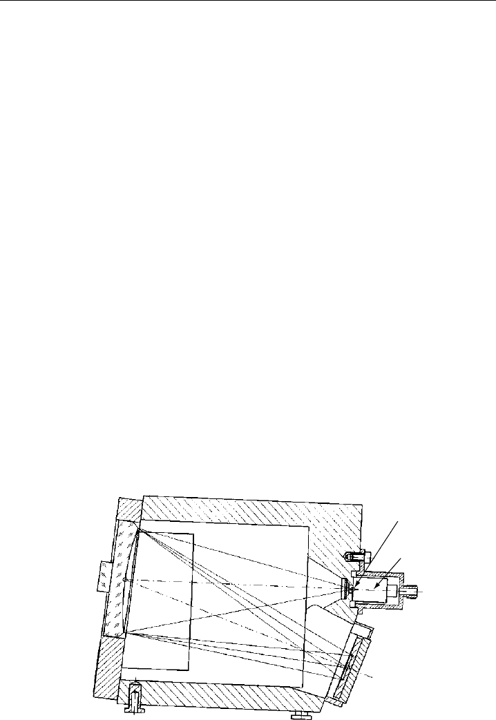
Measurement of Photolysis Frequencies in the Atmosphere 441
exit slit is replaced by a photodiode array (PDA) (Schmitt, 1999; Jäkel et al., 2005) or a
charge-coupled device (CCD) (Eckstein et al., 2003). In this way, the complete spectrum
can be recorded simultaneously in seconds. An example of a multi-channel spectrometer
(manufactured by Zeiss GmbH, Jena, Germany), used, for example, by Schmitt (1999)
and Jäkel et al., (2005), is shown schematically in Figure 9.18. The collected light is
coupled into the spectrometer via a quartz fibre which is connected to the entrance
slit via a cross-section converter (round to rectangular). A flat-field grating disperses
the radiation and images the spectrum onto a 512-element detector array. Photoelectric
charge generated by the incident photon flux is accumulated on each detector element
during a pre-selected exposure time and is then read out by an analogue–digital converter.
The digitized spectrum covers usually a usable range from 300 to about 700 nm and is
stored in a computer for further data processing.
Detector array–based spectrograph systems have a number of advantages compared
to scanning spectrometers, making them particularly useful for field applications (cf.
Table 9.5):
•
They measure a broader wavelength range in a tenfold to hundredfold shorter time.
•
They measure the complete spectrum simultaneously.
•
There are no moving parts, making the spectrometer more robust.
•
The spectrometer is more compact and lighter.
Probably the most important advantage for the measurement of ambient solar radiation
is the fast and simultaneous recording of complete spectra. This capability ensures an
accurate representation of the spectra with good time resolution even when the actinic flux
changes quickly. In contrast, spectra recorded sequentially by scanning spectroradiometers
may be distorted due to temporal intensity fluctuations during a wavelength scan. This
is relevant, for example, when measurements are performed under cloudy conditions on
fast-flying aircraft.
Photodiode array
detector
Flat-field grating
Entrance slit
Cross-section
converter
Fibre coupler
Ceramic body
Figure 9.18 Schematic of the optical layout of a spectrograph that uses a photodiode array detector for
the detection of the dispersed radiation spectrum (adapted from Zeiss GmbH, 1998, used with permission
of Zeiss company).

442 Analytical Techniques for Atmospheric Measurement
The main disadvantage of detector-array based spectrometers is the higher instru-
mental stray-light level compared to double-monochromator systems. Stray light is by
definition unwanted light that reaches a detector element from wavelengths that lie
outside the spectrometer bandpass. Stray light reaches the detector in an irregular way,
for example by random scatter from optical surfaces (mirrors, gratings etc.) and walls
inside the spectrometer. The relevance of stray light depends in particular on the spectral
distribution of the light source. In case when solar radiation is measured, stray light
is contributed mainly by the visible portion of the solar spectrum and produces a
background signal on every detector element, reducing the useful dynamic intensity-range
of a detector-array based spectrometer by about 2–3 orders of magnitude compared to
double-monochromator systems (see e.g. Bais et al., 2003). This presents a particular
problem for the measurement of the relatively low photon-fluxes found in the UV-B
region. In order to convert the measured signals into reasonable radiation data, sensitive
stray-light corrections are needed in the UV-B, which requires a thorough analysis of the
instrumental stray-light characteristics (e.g. Edwards & Monks, 2003; Kanaya et al., 2003;
Eckstein et al., 2003; Jäkel et al., 2005; Ylianttila et al., 2005).
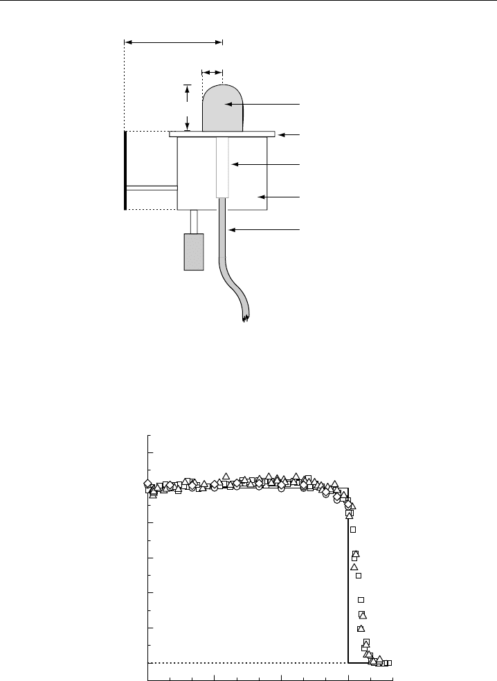
9.4.3 Actinic-flux receiver optics
Most of the actinic-flux spectroradiometers listed in Table 9.5 use the same type of
hemispheric quartz-diffuser for sunlight collection as shown in Figure 9.19. The diffuser
is a rigid construction made of a set of concentric frosted quartz-domes, which collect
radiation from a single hemisphere and couple all received light with nearly equal
efficiency into a quartz light guide. Radiation from the opposite hemisphere is mostly
blocked by a shadow ring serving as an artificial horizon. The design of the isotropic
receiver is based on a concept that was originally developed by Junkermann et al., (1989).
It was further improved by Volz-Thomas et al. (1996) and is now being manufactured
by Meteorologie Consult GmbH (Glashütten, Germany).
The relative angular response Z
p
of the receiver optic must be known for the accurate
evaluation of the spectrometer measurements (see Section 9.4.4). It can be measured in
the laboratory by exposing the receiver to radiation from a point source (lamp) that is
scanned at a constant distance over different polar () and azimuth angles () relative
to the symmetry axis of the diffuser. An example of results is shown in Figure 9.20
displaying polar-angle scans at different azimuthal angles for a fixed wavelength setting.
Note that Z
p
is normalised to be unity at the angle of incidence =0
. The agreement of
the scans at different azimuthal angles shows that Z
p
can be considered to be rotationally
symmetric. In principle Z
p
may exhibit a weak wavelength dependence. A negligible
dependence was reported for the 300–420 nm range by Hofzumahaus et al. (1999) and
Shetter and Müller (1999), while Jäkel et al. (2005) found a dependence of up to ±4%
from 300 to 700 nm for a similar receiver.
The measured Z
p
curves may be compared to the response function of an ideal 2 sr
detector (solid lines in Figure 9.20). Owing to its vertical extension, the real receiver
collects some radiation from below the artificial horizon line. The limiting polar angle at
which Z
p
approaches zero can be estimated geometrically from the ratio of the vertical
diffuser height and the radius of the shadow ring.
Measurement of Photolysis Frequencies in the Atmosphere 443
h
Shadow ring
Quartz diffuser
Quartz fibre bundle
r
2
r
1
Drying
cartridge
Housing
Mounting plate
Quartz light guide
Figure 9.19 Schematic diagram of a receiver optic h ≈ 35mmr
2
≈ 15mm for actinic-flux detection.
A shadow ring r
1
≈ 75–150 mm serves as an artificial horizon to restrict the field-of-view to one
hemisphere 2sr. A drying cartridge prevents condensation of humidity at cold ambient temperatures.
The quartz fiber bundle connects the diffuser to the entrance of the monochromator (adapted from
Hofzumahaus et al., 1999, used with permission of Optical Society of America).
0306090
0.0
0.2
0.4
0.6
0.8
1.0
1.2
Relative angular response Zp
Polar angle (degree)
Figure 9.20 Relative angular sensitivity Z
p
as a function of polar angle , measured for the 2sr
inlet-optic of a spectroradiometer operated at Forschungszentrum Jülich. The different symbols denote
measurements at four different azimuthal angles ( =0
90
180
, and 270
) at 300 nm. The solid line
represents the response of an ideal 2 sr actinic-flux detector.

444 Analytical Techniques for Atmospheric Measurement
In order to measure 4 sr actinic fluxes, different radiometer concepts have been
realised in field experiments:
•
One solution is to use two identical spectrometers each of which is equipped with a
2 sr receiver optic. In this case, the inlet optics are oriented into opposite directions
(upside and downside) in order to cover the full solid angle of 4 sr. This concept
has been applied for airborne measurements by Shetter and Müller (1999) and Jäkel
et al. (2005). A corresponding approach utilising filter radiometers was realised by
Volz-Thomas et al. (1996).
•
In another aircraft experiment, two 2 sr receiver optics (upside and downside looking)
were attached to the same spectroradiometer (Hofzumahaus et al., 2002). Here the inlet
optics were connected via fibre bundles to the upper and lower part of the entrance
slit of a double-monochromator. Owing to the imaging properties of the spectrometer,
the dispersed radiation from the two inlet optics could be separated at the exit slit and
measured independently by two photodetectors.
•
In a ground-based field study, Eckstein et al. (2003) used a receiver-optic with a field-
of-view of almost 4 sr. The home-built inlet-optic consisted of a teflon sphere of
30 mm diameter which was connected to the entrance slit of a spectrograph by a thin
quartz mono-fibre. Three of such receiver systems were attached in a vertical order
over the height of the entrance slit, producing three vertically separated spectra in the
focal plane of the spectrograph. The spectra were measured simultaneously by a CCD
camera with two-dimensional resolution. This set-up was deployed for measurements
at three different heights (4–100 m) on a tower in clouds.
9.4.4 Determination of spectral actinic fluxes
When a spectroradiometer is exposed to solar radiation in the atmosphere, the spectral
radiometer signal I
can be related to the atmospheric spectral radiance L
by the
following expression (Hofzumahaus et al., 1999):
dI
= D L
d (9.30)
Depending on the kind of photodetection the radiometer signal may be a photoelec-
trical current from a photomultiplier tube or accumulated photoelectric charge from a
photodiode array.
D denotes the absolute detection sensitivity of the entire spectroradiometer and may
be factorised as:
D =D
0
Z
p
(9.31)
D
0
is the wavelength-dependent value of D at =0
and Z
p
describes the relative sensi-
tivity of the entrance optic with respect to the direction of the incoming radiation
at a given wavelength. Note that Z
p
is dimensionless and by definition unity at = 0
.
In field conditions the entrance optic integrates the atmospheric radiation over all angles
of incidence. On the assumption that Z
p
has no significant azimuthal dependence (cf.
Figure 9.20), the resulting spectroradiometer signal I
at a given wavelength is given by
I
= D
0
4 sr
Z
p
L
d (9.32)

Measurement of Photolysis Frequencies in the Atmosphere 445
By introducing the dimensionless function Z
H
Z
H
=
1
F
4 sr
Z
p
L
d (9.33)
the following relation between I
and the actinic flux F
can be derived from
Equation 9.32:
I
= D
0
Z
H
F
(9.34)
In case of an ideal actinic-flux detector, with Z
p
= 1 for all angles of incidence,
Equation 9.33 gives Z
H
= 1 and equation 9.34 becomes:
I
ideal
= D
0
F
(9.35)
Comparison with Equation 9.34 shows that Z
H
represents a correction factor for the
non-ideal angular response of the real detector. Accordingly, the actinic flux can be
derived from the measured signal I
as
F
=
1
D
0
Z
H
I
(9.36)
Here, the evaluation of F
requires the absolute detection sensitivity D
0
and the
angular-response correction Z
H
of the radiometer, both of which can be obtained by
calibrations (see Section 9.4.5).
9.4.5 Spectroradiometer calibration
9.4.5.1 Angular-response correction
The correction factor Z
H
can be determined by Equation 9.33 from measured Z
p
values
and the relative angular distribution of the atmospheric radiance L
estimated by a
model. A general procedure to determine Z
H
for ground-based upward-looking receivers
has been described by Hofzumahaus et al. (1999) (see Appendix A.4). The application to
ground-based 4 sr measurements was presented by Eckstein et al. (2003) and airborne
measurements using a pair of upward and downward oriented receivers were discussed
by Volz-Thomas et al. (1996), Hofzumahaus et al. (2002) and Jäkel et al. (2005).
The Z
H
corrections for upward-looking receivers are usually small (<5%) over ground
surfaces with low albedo (<10%). Because the hemispheric receiver optics have some
sensitivity to radiation from the opposite hemisphere, the corrections can increase to
values of 10–15%, when measurements are performed above strongly reflecting surfaces
like snow or clouds (Hofzumahaus et al., 1999; Jäkel et al., 2005).
Downward looking receivers that measure the upwelling actinic radiation need generally
larger Z
H
corrections (<30%). In this particular case, the unwanted contribution of
radiation from the opposite hemisphere is relatively large, because the downward actinic
flux is larger than the upward directed component that is to be measured. The Z
H
correction applied to the downward oriented receiver has, however, relatively little
influence on the determination of the total, upward plus downward, actinic flux (Volz-
Thomas et al., 1996; Hofzumahaus et al., 2002; Jäkel et al., 2005).
446 Analytical Techniques for Atmospheric Measurement
9.4.5.2 Actinic-flux calibration
The calibration of the absolute detection sensitivity D
0
can be achieved by laboratory
measurements using certified calibration lamps (Hofzumahaus et al., 1999). The method
is based on the equivalence of the spectral actinic flux F
and the spectral irradiance E
for collimated radiation incident at = 0
:
F
= 0
= E
= 0
(9.37)
For this condition and considering that Z
p
= 0
= 1, integration of Equation 9.32
yields
I
= D
0
E
(9.38)
Using this equation, D
0
can be directly derived from the measurement of the certified
irradiance output of a calibration lamp. This procedure has the advantage that the
calibration of the actinic-flux spectroradiometer becomes traceable, via readily available
irradiance standards, to national laboratory standards (e.g. from NIST, NPL, PTB).
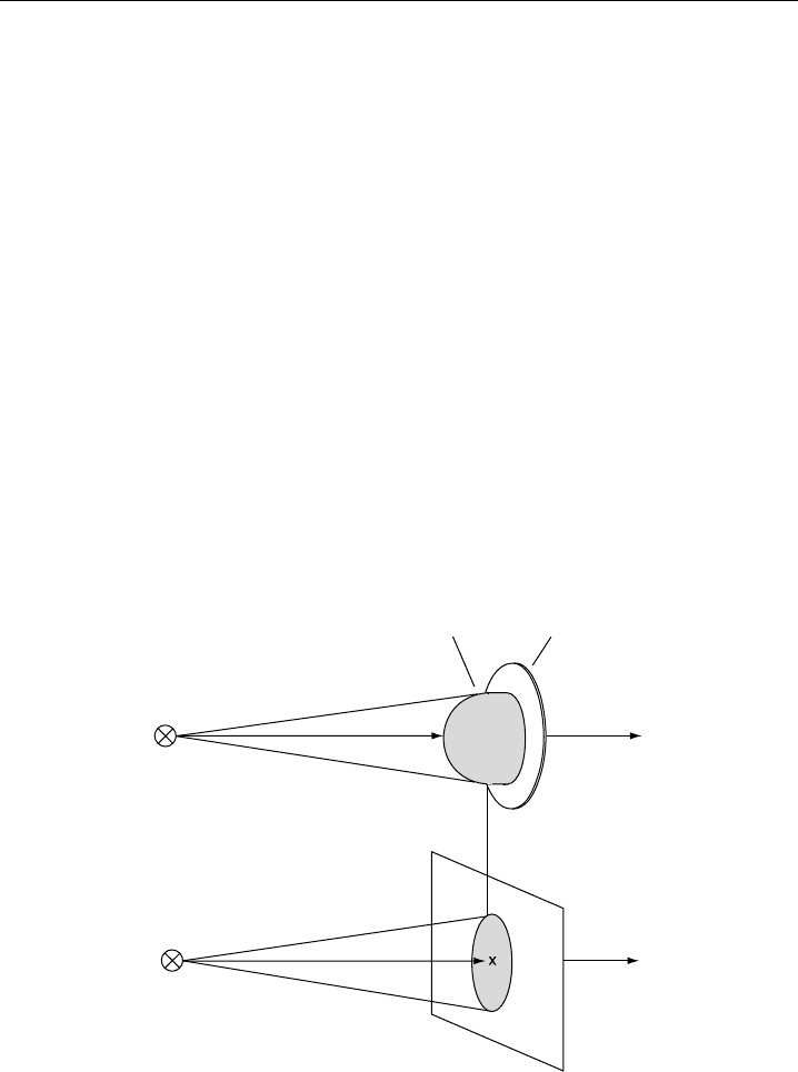
The application of the concept is complicated by the fact that the surface of the receiver
optic is not flat, as is usually the case with irradiance detectors, but has a spatial extension
along the optical axis pointing to the calibration lamp (Figure 9.21). Irradiance lamps
z
z
0
Quartz diffuser
Mounting plate
Lamp
z
z
0
+
Δz
Lamp
Equivalent plane receiver
S
S
′
Figure 9.21 Three-dimensional receiver irradiated by a calibration lamp at the working distance z
0
from
a reference point (tip of the outer quartz dome) of the receiver. S is the outer surface of the diffuser.
The real detector can be thought to behave like a virtual plane receiver with an active surface S
, being
a projection of S. The displacement z of the plane of S
relative to the reference point has a distinct
value that is a fixed property of the real receiver (from Hofzumahaus et al., 1999, used with permission
of Optical Society of America).

Measurement of Photolysis Frequencies in the Atmosphere 447
behave as point sources for which the irradiance is proportional to the inverse square of
the distance. For this reason the lamp output is certified for a prescribed distance from
the lamp (usually 50–70 cm). The longitudinal dimension of an actinic-flux receiver is
typically 3 cm (Figure 9.19). Thus, the irradiance from a lamp, operated at a distance
of 60 cm, varies about 10% from the top to the bottom of the receiver. The practical
problem is to find the correct working distance between the lamp and the receiver that
corresponds to the certified irradiance values of the lamp.
The problem is solved by an equivalent plane-receiver (EPR) concept (Hofzumahaus
et al., 1999). The three-dimensional receiver can be thought to be replaced by a plane
receiver, which is irradiated at normal incidence and has the following properties
(Figure 9.21).
1. The EPR and the real detector exhibit the same absolute detection sensitivity D
0
with respect to a radiation source located at a working distance z
0
from a reference
point of the real receiver. Both receivers yield the same measurement signal I
when
irradiated by a calibration lamp.
2. The active surface S
of the EPR is a projection of the surface S of the real receiver
onto an imaginary plane perpendicular to the optical axis z.
3. The imaginary plane of the EPR has a well-defined position, being displaced relative
to the reference point of the quartz diffuser by a fixed length z along the optical axis.
z is a specific property of the real receiver and is independent of z
0
.
This concept is valid with a small error of less than 1%, if the longitudinal dimension of
the diffuser is less than 6% of the working distance (see Appendix A.5). The validity of
the EPR concept has two important implications:
1. Since the real receiver behaves like an EPR, z can be determined experimentally from
I
values, which are measured at different distances z
0
and follow the inverse-square
law:
I
=
const
z
0
+z
2
(9.39)
If the measured data are plotted as I
−1/2
versus z
0
, z can be extrapolated from a
linear fit for the condition I
−1/2
= 0.
2. Once that z is known, the spectroradiometer can be calibrated accurately by using
Equation 9.38, provided that the working distance z
0
is set equal to (z
∗
−z) where
z
∗
is the prescribed distance for which the irradiance standard is certified.
In practice, the most accurate calibrations are performed in the laboratory using 1000 W
tungsten–halogen quartz lamps (FEL type) as irradiance standards. For best accuracy, the
lamps need to be operated with highly stable power supplies that keep the lamp current
constant within about 10
−5
of the value specified in the lamp certificate (see, for example,
Gardiner & Kirsch, 1995). The error of the absolute calibration obtained in the laboratory
is typically around ±5%. It is mainly caused by the uncertainty of the irradiance standard
certification (typ. 4%, in the UV, 2) and by the determination of the correct working
distance (typ. 1–2%) (e.g., Hofzumahaus et al., 1999; Eckstein et al., 2003; Edwards &