Hancock G.J., Murray Th.M., Ellifritt D.S. Cold-Formed Steel Structures to the AISI Specification
Подождите немного. Документ загружается.

10.4 SYSTEM ANCHORAGE REQUIREMENTS
10.4.1 Z-Purlin Supported Systems
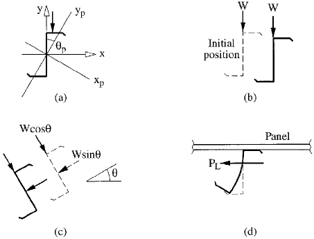
The principal axes of Z-purlins are inclined from the center-
line of the web at an angle y
p
, as shown in Figure 10.12a.
For Z-purlins commonly used in North America, y
p
is
between 20
and 30
. For an unrestrained purlin, the
component of the roof loading that is parallel to the web
causes a Z-purlin to de¯ect in the vertical and horizontal
directions, as shown in Figure 10.12b. The component of
the roof loading perpendicular to the purlin web decreases
the de¯ection perpendicular to the web. For steep roofs this
component can even cause movement in the opposite direc-
tion, as shown in Figure 10.12c. Since the bottom ¯ange of
the purlin is restrained at the rafter connection and the top
¯ange is at least partially restrained by the roof deck, a
purlin tends to twist or ``roll'' as shown in Figure 10.12d.
Devices such as antiroll clips at the rafters or intermediate
lateral braces are used to minimize purlin roll. The force
FIGURE 10.12 Z-purlin movement: (a) axes; (b) unrestrained
movement; (c) movement because of large downslope component;
(d) panel and anchorage restraints.
Chapter 10
318
induced in these devices is signi®cant and must be consid-
ered in design.
From basic principles (Ref. 10.16), the required
anchorage or restraint force for a single Z-purlin with
uniform load (W ) parallel to the web is
P
L
0:5
I
xy
I
x
W 10:7
where I
xy
is the product moment of inertia and I
x
is the
moment of inertia with respect to the centroidal axis
perpendicular to the web of the Z-section as shown in
Figure 10.12a. For this formulation, the required anchor-
age force for a multi-purlin-line system is directly propor-
tional to the number of purlins (n
p
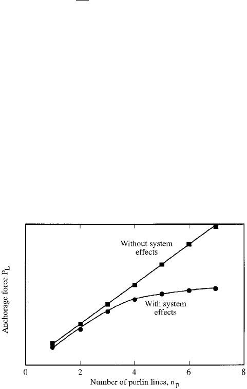
). However, Elhouar and
Murray (Ref. 10.17) showed that the anchorage force
predicted by Eq. (10.7) is conservative because of a system
effect. Figure 10.13 shows a typical result from their study.
The straight line is from Eq. (10.7), and the curved line is
from stiffness analyses of a multi-purlin-line system. The
difference in the anchorage force between the two results is
a consequence of the inherent restraint in the system due to
purlin web ¯exural stiffness and a Vierendeel truss action
FIGURE 10.13 Anchorage forces vs. number of purlin lines.
Roof and Wall Systems
319
caused by the interaction of purlin webs with the roof panel
and rafter ¯anges. This Vierendeel truss action explains the
relative decrease in anchorage force as the number of purlin
lines (n
p
) increases, as shown in the ®gure.
Section D3.2.1 of the AISI Speci®cation has provisions
that predict required anchorage forces in Z-purlin-
supported roof systems supporting gravity loading and
with all compression ¯anges facing in the same direction.
The provisions were developed by using elastic stiffness
models of ¯at roofs (Ref. 10.17) and were veri®ed by full-
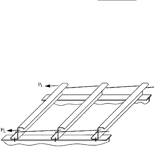
scale and model testing (Ref. 10.18). For example, the
predicted anchorage force in each brace (P
L
) for single-
span systems with restraints only at the supports, Figure
10.14, is
P
L
0:5bW; with b
0:220b
1:5
n
0:72
p
d
0:90
t
0:60
10:8
where W applied vertical load (parallel to the web) for
the set of restrained purlins
b ¯ange width
d depth of section
t thickness
n
p
number of restrained purlin lines
FIGURE 10.14 Single-span purlin system with anchorage at
rafters.
Chapter 10
320
The restraint force ratio, b, represents the system effect
and was developed from regression analysis of stiffness
model results.
Assuming that the top ¯ange of the Z-purlin is in the
upslope direction, the anchorage force P
L
for single-span
systems with restraints only at the rafter supports becomes
P
L
0:5b cos y ÿ sin yW 10:9
with y roof slope measured from the horizontal as shown
in Figure 10.12c. The terms W b cos y and W sin y are the
gravity load components parallel and perpendicular to the
purlin web, respectively. The latter component is also
referred to as the downslope component. Equations of this
form are included in AISI Speci®cation Supplement No. 1.
Two important effects were not taken into account in
the development of Eq. (10.9). First, the internal system
effect b applies to the forces W cos y and W sin y. Second,
the internal system effect reverses when the net anchorage
force changes from tension to compression with increasing
slope angle. Further, the stiffness models used to develop
the AISI provisions assume a roof panel shear stiffness of
2500 lb=in., whereas the actual shear stiffness can be
between 1000 lb=in. (standing seam sheathing) to as high
as 60,000±100,000 lb=in. (through-fastened sheathing).
Neubert and Murray (Ref. 10.19) have recently
proposed the following model, which eliminates the de®-
ciencies inherent in Eq. (10.9). They postulate that the
predicted anchorage force in any given system is equal to
the anchorage force required for a single purlin (P
0
) multi-
plied by the total number of purlins (n
p
), a brace location
factor (C
1
), a reduction factor due to system effects (a), and
modi®ed by a factor for roof panel stiffness (g). Thus,
P
L
P
0
C
1
n
p
*a n
p
g10:10
Roof and Wall Systems
321
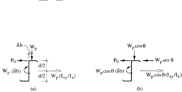
Figure 10.15a shows a Z-purlin with zero slope and
applied load W
p
, which is the total gravity load acting on
each purlin span:
W
p
wL 10:11
where w distributed gravity load on each purlin
(force=length)
L span length
The ®ctitious force W
p
I
xy
=I
x
) is the ®ctitious lateral force
from basic principles (Ref. 10.16). The couple W
p
db results
from the assumed location of the load W
p
on the ¯angeÐ
that is, db from the face of the web as shown in Figure
10.15a. Figure 10.15b shows the set of real and ®ctitious
forces associated with a single purlin on a roof with slope y.
The purlin is assumed to be pinned at the rafter connection.
The set of forces accounts for the following effects: W
p
sin y
is the downslope component, W
p
cos yI
xy
=I
x
) is the down-
slope component of the ®ctitious lateral force, and
W
p
cos ydb) is the net torque induced by eccentric loading
of the top ¯ange. Summation of moments about the pinned
support results in
P
0
I
xy
2I
x
db
d
cos y ÿ sin y
W
p
10:12
For low slopes, P
0
is positive (tension) and for high
slopes P
0
is negative (compression). A positive value indi-
cates that the purlin is trying to twist in a clockwise
FIGURE 10.15 Modeling of gravity loads: (a) forces for a single
purlin on a ¯at roof; (b) forces for a single purlin on a sloping roof.
Chapter 10
322

direction; a negative value means twist is in the counter-
clockwise direction. The anchorage force is zero for
y
0
tan
ÿ1
I
xy
2I
x
db
d
10:13
For y < y
0
; P
0
is in tension, and for y > y
0
; P
0
is in compres-
sion. The distance db has a signi®cant effect on the value of
the intercept angle y
0
. In Ref. 10.19, db was taken as b=3,
based on anchorage forces measured in tests of zero-slope
roof systems (Ref. 10.17).
Statistical analysis of stiffness model results was used
to develop a relationship for the system effect factor a:
a 1 ÿ C
2
t
d
n
p
* ÿ 110:14
with C
2
a constant factor that depends on the bracing
con®guration and n
p
* is described below. The factor a is
dimensionless and, when included in Eq. (10.10), models
the reversal of the system effect when P
0
changes from
tension to compression. The coef®cient C
2
was determined
from a set of regression analyses with values tabulated in
Table 10.1. The value of the coef®cient differs for each
bracing con®guration because bending resistance changes
depending on the distance between a brace and rafter
supports or other braces.
Equation (10.10) is quadratic with respect to n
p
,
because a is linear with n
p
. For some value of n
p
, denoted
as n
pmax
; P
L
will reach a maximum and then decrease as
n
p
is increased above n
pmax
. From basic calculus, n
pmax
is
determined as
n
pmax
0:5
d
2C
2
t
10:15
However, the required anchorage force can never decrease
as the number of purlins is increased. Therefore n
p
* is used
in Eqs. (10.10) and (10.14) instead of n
p
, where n
p
* is the
Roof and Wall Systems
323
minimum of n
pmax
and n
p
. In other words, P
L
remains
constant when the number of purlin lines exceeds n
pmax
.
The brace location factor C
1
in Eq. (10.10) represents
the percentage of total restraint that is allocated to each
brace in the system. The sum of the C
1
coef®cients for the
braces in a span length is approximately equal to unity. The
values for C
1
were determined from a regression analysis
and are tabulated for each bracing con®guration in Table
10.1. For multiple span systems, the C
1
values are larger
for exterior restraints than the corresponding interior
restraints, as expected from structural mechanics.
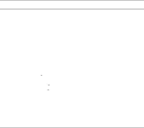
Figure 10.16 shows a typical plot comparing the Eq.
(10.10) with, g 0, to the AISI Speci®cation Eq. (10.9) with
respect to slope angle y. Equation (10.10) predicts slightly
TABLE 10.1 Anchorage Force Coef®cients for Use in Eq. (10.10)
Bracing con®guration C
1
C
2
C
3
Support anchorages only
Single span 0.50 5.9 0.35
Multispan, exterior supports 0.50 5.9 0.35
Multispan, interior supports 1.00 9.2 0.45
Third-point anchorages
Single span 0.50 4.2 0.25
Multispan, exterior spans 0.50 4.2 0.25
Multispan, interior spans 0.45 4.2 0.35
Midspan anchorages
Single span 0.85 5.6 0.35
Multispan, exterior spans 0.80 5.6 0.35
Multispan, interior spans 0.75 5.6 0.45
Quarter-point anchorages
Single span, outside
1
4
points 0.25 5.0 0.35
Single span, midspan location 0.45 3.6 0.15
Multispan, exterior span
1
4
points 0.25 5.0 0.40
Multispan, interior span
1
4
points 0.22 5.0 0.40
Multispan, midspan locations 0.45 3.6 0.25
Third-point plus support anchorages
Single span, at supports 0.17 3.5 0.35
Single span, interior locations 0.35 3.0 0.05
Multispan, exterior support 0.17 3.5 0.35
Multispan, interior support 0.30 5.0 0.45
Multispan, third-point locations 0.35 3.0 0.10
Chapter 10
324
greater anchorage force for low-slope roofs and signi®cantly
less anchorage force for high-slope roofs. The latter is due
to the inclusion of system effects in the downslope direction
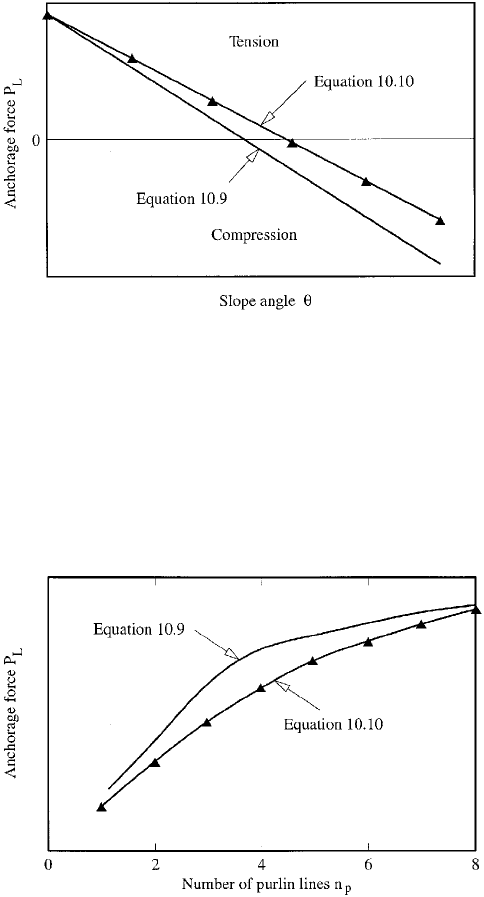
which are ignored in the AISI provisions. Figure 10.17
shows a similar plot with respect to the number of
restrained purlin lines.
FIGURE 10.16 Anchorage force vs. roof slope: Eqs. (10.9) and
(10.10).
FIGURE 10.17 Anchorage force vs. number of purlins: Eqs. (10.9)
and (10.10).
Roof and Wall Systems
325
The stiffness models used to develop the AISI provi-
sions, Eq. (10.9), included a roof deck diaphragm stiffness of
G
0
2500 lb=in. with the assumption that the required
anchorage force for systems with roof decks stiffer than
2500 lb=in. is negligible. Roof deck diaphragm stiffness was
taken as
G
0
PL
4aD
10:16
where P point load applied at midspan of a rectangular
roof panel,
L panel's span length
a panel width
and
D de¯ection of the panel at the location of the
point load.
In Ref. 10.19 stiffness models of roof systems with up
to eight restrained purlins were analyzed, and it was found
that deck stiffness above 2500 lb=in. caused signi®cant
increases in the anchorage forces for systems with four or
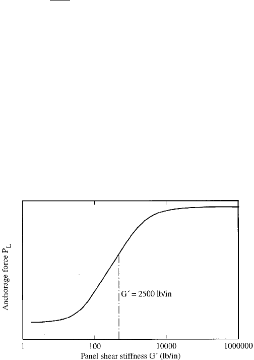
more purlin lines. The panel stiffness modi®er (g) in Eq.
(10.10) accounts for this effect. As shown in Figure 10.18,
FIGURE 10.18 Anchorage force vs. panel stiffness (stiffness
model).
Chapter 10
326

the anchorage force varies linearly with the common loga-
rithm of the roof panel shear stiffness over a ®nite range of
stiffnesses, which leads to the following equation for the
panel stiffness modi®er:
g C
3
log
G
0
2500 lb/in.
10:17
where G
0
roof panel shear stiffness (lb=in.)
C
3
constant from regression analysis of stiffness
model
When G
0
2500 lb=in., g 0 as necessary, and g is
positive for G
0
> 2500 lb=in. and negative for
G
0
< 2500 lb=in. Thus, when G
0
> 2500 lb=in., the ancho-
rage force is increased, and when G
0
< 2500 lb=in., the
required anchorage force is decreased. The values of C
3
,
which depend on the location of a brace relative to rafter
supports and other braces, are tabulated for each bracing
con®guration in Table 10.1.
The effect of g is to adjust the system effect factor, a.In
Eq. (10.10) g is multiplied by n
p
instead of n
p
*, because as
panel stiffness changes, change in anchorage force depends
on the total number of purlins in the system and n
pmax
no
longer applies. The panel stiffness modi®er g is valid only
for 1000 lb=in. G
0
100,000 lb=in. This is the range of
linear behavior and most roof decks have shear stiffness
within this limitation.
For very large panel stiffness, Eq. (10.10) can predict
an anchorage force greater than that obtained from basic
principles [Eq. (10.7)]. However, the maximum anchorage
force is the anchorage force ignoring system effects. Thus,
P
L
P
0
C
1
n
p
10:18
Figure 10.19 is a typical plot of anchorage force versus
panel stiffness for Eq. (10.10), compared with stiffness
model results.
Since the stiffness models used to develop Eq. (10.10)
had eight purlin lines or fewer, Eq. (10.10) must be used
Roof and Wall Systems
327