Gulian A.M., Zharkov G.F. Nonequilibrium Electrons and Phonons in Superconductors
Подождите немного. Документ загружается.


SECTION 9.3. ANALYSIS OF RESULTS 231
superconducting filament are shifted along the abscissa relative to the normal state
Ohm’s law by an excess current The phenomenon of excess current was
observed experimentally in short superconducting bridges
22–28
; however, we will
not discuss this question here in more detail (see Sect. 10.5 and Ref. 29). The periods
of stable oscillations
t
p
, which are related to V by expression (9.45), are shown in
Fig. 9.9b in dependence on the transport current j.
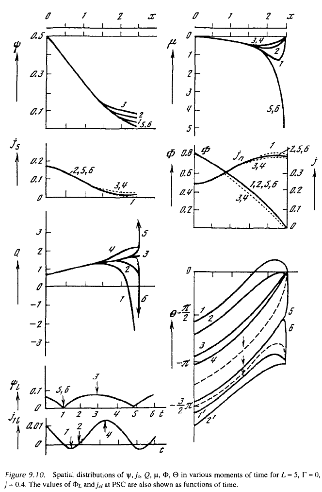
9.3.4. Other Boundary Conditions
Figure 9.10 demonstrates the behavior of in the case
L
= 5,
for the boundary condition (9.14) with The
distributions are presented on one half of the interval 0 only. For sym-
metry reasons the functions * are even relative to the point
l
=
L
/2 [i.e.,
and the functions and are odd The numeration
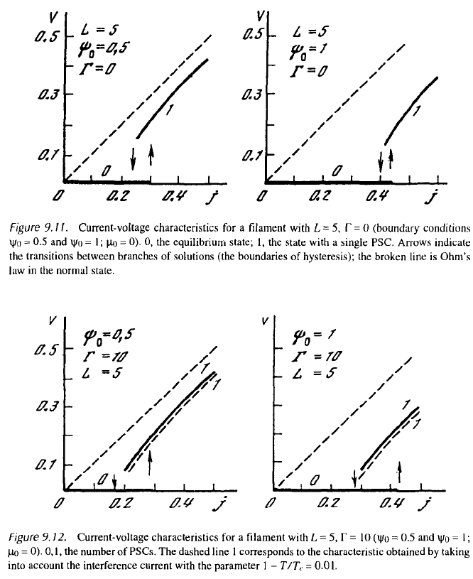
of the curves hereafter corresponds to that used in Fig. 9.4. The voltage-current
characteristics for are given in Fig. 9.11.
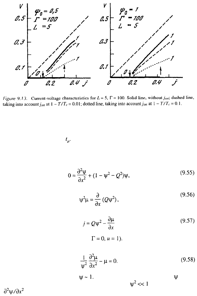
9.3.5. Finite-Cap Results
The results presented in the preceding section relate to the gapless state
For finite-gap superconductors the qualitative picture of the
processes occurring in the filament does not change significantly. Figures 9.12 and
9.13 depict the voltage-current characteristics for superconducting filaments with
for the boundary conditions
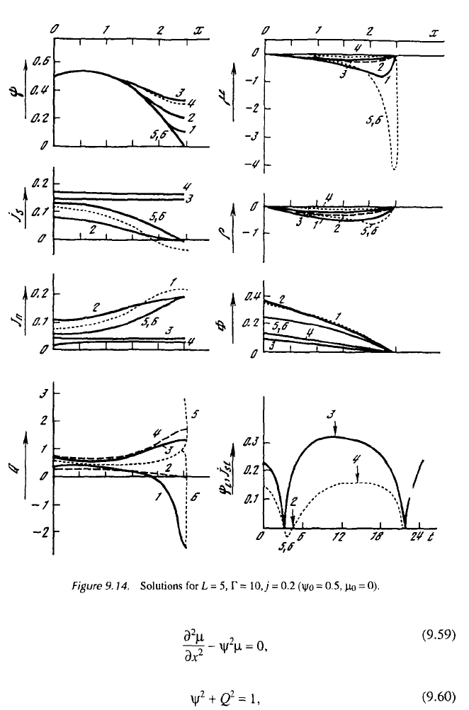
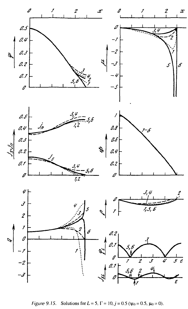
(solid lines). The solutions for L = 5, at
j
= 0.2 and
j
= 0.5 are shown in Figs. 9.14, and 9.15. For finite-gap superconductors,
the space distribution of electric charge arises along the filament driven into the
resistive state. The charge is proportional to and has opposite signs to the left
and to the right of PSC, so that the total charge is zero. The solutions for
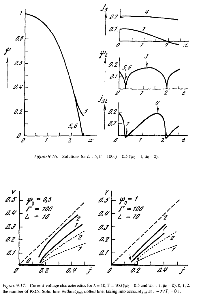
and
j
= 0.5 are shown in Fig. 9.16.
9.3.6. Two Active Centers
For
L
= 10, along with the solution corresponding to one PSC in the middle
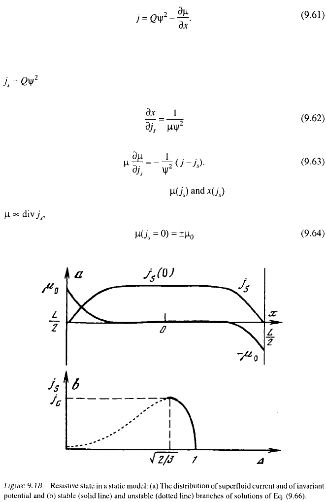
point, a solution with two phase-slip centers occurs. Figure 9.17 depicts voltage-
current dependencies for
As mentioned at the beginning of this chapter, spontaneous jumps were
detected in the experiments registering current-voltage characteristics in the resis-
tive states. These jumps may be explained by the creation of a new PSC and by
corresponding transitions from one branch of the solution to another (see Fig. 9.17).
232 CHAPTER 9. PHASE-SLIP CENTERS
SECTION 9.3. ANALYSIS OF RESULTS 233
9.3.7. Current-Voltage Relations: Galayko Model
It should be pointed out that some features of the current-voltage characteristics
(such as those depicted in Fig. 9.1) may be well described by the analytic solutions
of the static equations (9.4) to (9.8), or, more properly, by a static version of these
equations proposed by Fink et al., and by Galayko et al. (the “static model,” see,
e.g., Refs. 30–34). The applicability of static equations is connected with the fact
234 CHAPTER 9. PHASE-SLIP CENTERS
that the oscillations of physical quantities at PSC are of high frequency, but the
current-voltage characteristics are observed on time intervals significantly larger
than the oscillation period
Averaging Eqs. (9.4) and (9.5) over time, keeping only nonzero terms and
replacing the mean values of compositions by the compositions of mean (nonzero!)
values, one obtains the equations
(to simplify the equations we make Using the relation (9.57), we
transform (9.56) into the form
In thermodynamic equilibrium, In the resistive state, the value of dimin-
ishes. Thus in the vicinity of PSC one can assume and omit the term
in the set of equations (9.55) and (9.58). Then the basic equations of the
static model are simplified further and reduced to
SECTION 9.3. ANALYSIS OF RESULTS 235
236
CHAPTER 9. PHASE-SLIP CENTERS
SECTION 9.3. ANALYSIS OF RESULTS 237
238 CHAPTER 9. PHASE-SLIP CENTERS
Despite the crudeness of the approximation, the main features of the current-voltage
characteristics (as can be seen) are described by Eqs. (9.59) to (9.61). Using the
method of solution proposed in Ref. 35, we choose a superconducting current
as the integration variable. Differentiating Eq. (9.61) over the coordinate
x and combining it with (9.59), one finds
The boundary conditions for the functions must be supplied to these
equations. Taking into account the symmetry of the problem and that of
we have
SECTION 9.3. ANALYSIS OF RESULTS 239
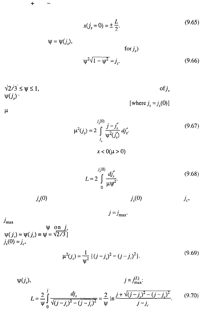
(the signs and refer to the left and right ends of the filament). The second
boundary condition is obvious (Fig. 9.18a):
The function appearing in (9.62) and (9.63) is determined by Eq.
(9.60), from which (accounting for the expression it follows that
The behavior of the solution of this equation is illustrated in Fig. 9.18b. Because
the thermodynamically stable branch of the solution corresponds to the values
one can assume that in the whole range of variation the function
varies slowly. This fact simplifies further analysis. Integrating Eq. (9.63) and
taking into account that at the center of the filament the value of
vanishes, we obtain
Integration of Eq. (9.62) in the range taking into account boundary
condition (9.65) gives the relation
The value of increases with increasing j. When attains the value the
creation of PSC becomes possible. At the constant length
L
, this occurs when the
total current j reaches a certain critical value Let us find a relation between
and L. As mentioned earlier, in the first approximation one can neglect the
dependence of in the expressions (9.67) and (9.68) [assuming
and fulfill the integration in quadratures. Setting
we find from (9.67):
Substituting this expression into (9.68) and neglecting the functional depend-
ence we obtain the following equation for
240 CHAPTER 9. PHASE-SLIP CENTERS
For a sufficiently long filament the relation
follows from (9.70), which connects The
quantity defines the critical current when the first PSC appears. Because the
boundary conditions at the point where the PSC exists coincide with the boundary
conditions for the junction of the superconductor and normal metal, for a suffi-
ciently long filament (the distance between PSCs must significantly exceed the
penetration depth we return to the initial problem, but for two consecutively
connected segments of the filament. If the current increases further, new PSCs arise,
with a critical current
corresponding to the creation of the
n
th
PSC. With the appearance of a subsequent
PSC, the voltage difference at the filament suffers a jump (which in the first
approximation does not depend on j). Taking into account (9.69), one can conclude
that between these jumps the current-voltage characteristics have linear sections
corresponding to the differential resistivity
The length of these sections between jumps (see Fig. 9.1) evolves with n as
In the static model, as we have seen, the creation of a new PSC
occurs when the current attains the value [in dimensionless units
In reality (owing to various physical factors) the quantitative crite-
rion of PSC creation may differ from this condition. In principle, a hysteresis is
possible at subsequent increases and decreases of the current through the filament.
We will not consider these details here.
9.3.8. Shortcomings of the TDGL in the Absence of Relaxation
Returning to the numerical analysis, we note that at large the values of
are also large at small distances from PSC and diverge formally at
[see expressions (9.5) and (9.9) for which is inadmissible for
physical reasons. From this limitations also follow on the applicability of the TDGL
set of equations for large values of