Grace Robert. Advanced Blowout and Well Control
Подождите немного. Документ загружается.

316
Advanced
Blowout
and
Well
Conhol
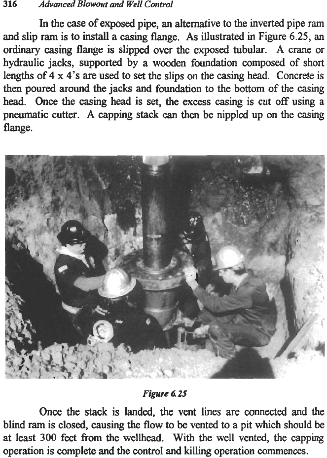
In
the case
of
exposed pipe, an alternative
to
the inverted pipe
ram
and slip
ram
is
to
install
a
casing flange.
As
illustrated in Figure
6.25,
an
or-
casing
flange is slipped over the exposed tubular.
A
crane or
hydraulic jacks, supported by
a
wooden foundation composed of short
lengths of
4
x
4’s
are used
to
set
the slips on the casing head. Concrete is
then poured around the
jacks
and foundation
to
the bottom of the casing
head.
Once
the casing head is
set,
the
excess
casing
is
cut
off
using a
pneumatic cutter.
A
capping stack
can
then
be
nippled up on the casing
flange.
Figure
4
25
Once
the stack is landed, the vent lines are
connected
and the
blind
ram
is closed, causing the flow
to
be
vented
to
a pit which should be
at
least
300
feet
from
the wellhead. With the well vented, the capping
operation is complete and the control and killing operation commences.
Special Services
in
Well Control
317
FREEZING
Freezing is
a
very usehl tool in well control. Invariably, the top
ball valve in the drill
string
will be too small
to
permit the running
of
a
plug.
In
order to remove the valve
with
pressure on the drillpipe, the
drillpipe would have
to
be
frozen.
A
wooden
box
is constructed around
the area
to
be
frozen.
Then,
a
very
viscous
mixture
of
bentonite and water
is
pumped into the drillpipe and spotted across the
area
to be frozen.
Next, the freeze box is filled with
dry
ice (solid carbon dioxide). Nitrogen
should never be used to freeze because it is
too
cold. The steel becomes
very brittle
and
may shatter when impacted. Several hours may be
required to obtain a good plug. The rule
of
thumb is one hour for each 1
inch in diameter to be fiozen. Finally, the pressure is bled from above the
faulty valve; it is removed and replaced and the plug
is
permitted to thaw.
Almost everything imaginable has
been
frozen including valves and
blowout preventers.
HOT
TAP
Hot tapping is another usehl tool in well control. Hot tapping
consists
of
simply flanging or saddling to the object to be tapped
and
drilling into the pressure.
For
example, an inoperable valve
can
be
hot tapped or
a
plugged joint
of
drillpipe can be hot tapped and the pressure safely bled
to
the atmosphere.
In
other instances,
a
joint
of
drillpipe has been
hot
tapped and kill fluid
injected through the tap.
Almost anythmg
can
be hot tapped.

CHAPTER
SEVEN
RELIEF WELL DESIGN AND
OPERATIONS
The industry
has
long considered the relief well option
as
a
last
resort in well control. The problems are obvious. Even
with
the best
surveying techniques, the bottom of the hole was unknown to any degree
of
certainty. The ability
to
communicate with the bottom
of
the hole was
very limited and most often governed by the principle
of
trial
and error.
However, relief well technology
has
advanced
in the past
10
years to the
point that a relief well is now a viable alternative. Modern technology
has
made intercepting the blowout a certainty and controlling the blowout
from the relief well a predictable engineering event.
HISTORY
ULSEL AND MAGNETIC INTERPRETATION INTRODUCED
On 25 March, 1970,
a
blowout occurred at the Shell Oil
Corporation Cox
No.
1
at
Piney
Woods,
Rankin
County, Mississippi.'
The well had been drilled into the Smackover at a
total
depth of 21,122
feet and cased to 20,607 feet. The well flowed at rates estimated between
30
and
80
million standard cubic feet of gas per day plus 14,000 to
20,000 barrels of water per
day.
The hydrogen sulfide concentration in the
gas
stream
made the gas deadly
toxic
to
humans
and, combined with the
saline, produced water deadly corrosive to steels. Shortly after the well
kicked on the moming of the disaster, the blowout preventer stack rose
and fell over, releasing
a
stream
of
gas
and invert oilemulsion mud.
Within minutes the well ignited and the derrick fell. The well had
cratered.
This
combination of events and circumstances made. surface
control
at
the Cox
No.
1
impossible. Therefore,
an
all-out effort was
made to control the blowout from
a
relief well.
A
conventional relief well,
318
Relief
Well
Design
and
Operations
319
Cox
No.
2,
was spudded on
3
May, 1970, at
a
surface location
3,500
feet
west of the blowout.
This
well was designed to
be
drilled straight to
9,000
feet and from there directionally to
21,000
feet
to
be bottomed close
to the Cox No.
1.
There was considerable skepticism about the effectiveness of
this
approach.
Was
directional drilling possible at these depths? Could the
bottom of the blowout
be
determined
with
any reasonable accuracy?
Could solids-laden fluid
be
communicated
to
the blowout
through
the
Smackover with its relatively low porosity and permeability? Because of
these uncertainties, a special task force was formed to explore new
techniques. On
16
May, 1970, the Cox
No.
4
was spudded 1,050
feet
east
of
the blowout.
Its
mission was
to
intercept the blowout in the
interval between 9,000 and 13,000 feet and effect
a
kill. The resulting
work was to pioneer modem relief well technology.
Two methods of evaluation were introdud and developed and
formed the basis for modem technology. One technique involved the use
of resistivity measurements to determine the distance between the relief
well and the blowout. The use
of
electrical logs for locating various
drillpipe and casing fishes in wellbores was well
known
and many
examples could be cited. However, little effort had been expended
to
utilize resistivity devices
as
a direct means of determining distance
between wells.
Also, there were very few examples of intersecting
wellbores. Due
to
the nature and depth of
the
reservoir
rocks,
a wellbore
intercept at or about
10,000
feet was necessary to effect
a
kill at the Cox
No.
1.
In
response to
this
disaster, Shell and Schlumberger developed
and reported the use of ultra-long, spaced electrical logs, commercially
known
as
ULSEL,
to
determine the distance between wells. The ULSEL
technology was developed primarily for the profiling of salt structures or
other resistive anomalies. The ULSEL tool is merely the old short-normal
technique
with
electrode spacings
of
150
feet for
AM
and
600
feet for the
A37
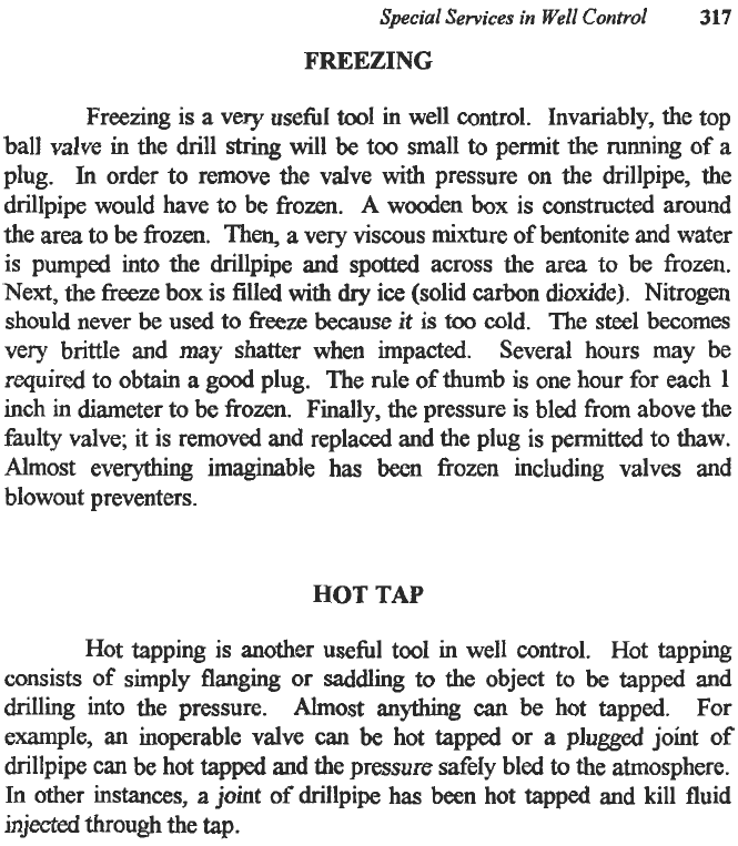
electrodes. An example of induction-electric
log
response in an
intersecting well is shown
in
Figure 7.1. Rather inaccurate estimates of
distances between wellbores are
made
by curve fitting techniques
designed
to
model the short-circuiting effect of the casing in the blowout.
At the
Amom
R.
L. Bergeron
No.
1
in the Moore-Sams Field near Baton
Rouge, Louisiana, which blew out in early
1980,
the ULSEL technology
320
predicted the blowout
to
be
12
to
18
feet from the relief well at
9,050
feet
measured depth.
In
reality, the blowout
was
approximately
30
feet
from
the relief well.'
Advanced
Bowosrt
and Well Control
n
Figure
Z
I
-
Short
Circuit
Eflect
of
Casing
Usel
Response
A
most interesting technique
was
developed by Shell Development
Company and reported by
J.
D.
Robinson and
J.
P.
Vogiatzis.
This
technique involved the utilization of sensitive magnetometers
to
measure
the earth's magnetic field and the distortion
of
that magnetic field resulting
from the presence
of
casing or other tubulars possessing remnant
magnetization. Measurements were made
from
the relief well and
sidetracks, and models were assumed in an effort
to
match the relative
Relief Well Design
and
Operations
321
position of the
two
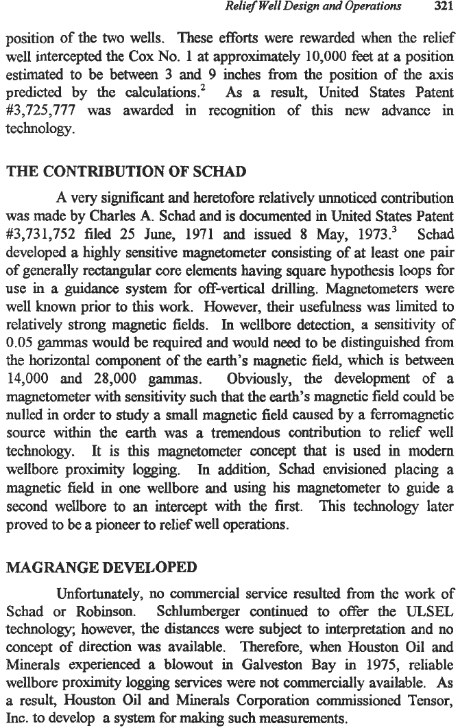
wells. These efforts were rewarded when the relief
well intercepted the Cox
No.
1
at approximately
10,000
feet
at a
position
estimated to be between
3
and
9
inches from the position of the
axis
predicted by the calculations.2
As
a
result, United States Patent
#3,725,777
m7as
awarded in recognition of this new advance
in
technology.
THE CONTRIBUTION OF SCHAD
A
very significant and heretofore relatively unnoticed contribution
was
made by Charles
A.
Schad and is documented in United States Patent
#3,731,752
filed
25
June,
1971
and issued
8
May,
1973.3
Schad
developed
a
highly sensitive magnetometer consisting of
at
least one pair
of generally rectangular core elements having square hypothesis loops for
use in
a
guidance system for off-vertical drilling. Magnetometers were
well
known
prior
to
this
work. However, their usefulness was limited to
relatively strong magnetic fields.
In
wellbore detection,
a
sensitivity of
0.05
gammas would be required and would need to be distinguished from
the horizontal component of the
earth’s
magnetic field, which is between
14,000
and
28,000
gammas. Obviously, the development of a
magnetometer
with
sensitivity such
that
the
earth’s
magnetic field could be
nulled in order to study a small magnetic field caused by a ferromagnetic
source within the
earth
was
a
tremendous contribution to relief well
technology. It is
this
magnetometer concept that
is
used in modem
wellbore proximity logging. ln addition, Schad envisioned placing a
magnetic field in one wellbore and using
his
magnetometer to guide a
second wellbore
to
an intercept with the first. This technology later
proved to be
a
pioneer
to
relief well operations.
MAGRANGE DEVELOPED
Unfortunately, no commercial service resulted from the work of
Schad or Robinson. Schlumberger continued
to
offer the
ULSEL
technology; however, the
distances
were subject
to
interpretation and no
concept of direction was available. Therefore, when Houston Oil and
Minerals experienced
a
blowout in Galveston Bay in
1975,
reliable
wellbore proximity logging services were not commercially available.
As
a result, Houston Oil and Minerals Corporation commissioned Tensor,
Inc.
to develop
a
system for making such measurements.
322
Advanced
Bowout
and Well
Control
In
response to that need and commission, Tensor developed the
MAGRANGE service. The MAGRANGE service
is
based on United
States Patent #4,072,200 which
was
filed 12 May, 1976 and issued to
Fred
J.
Moms,
et.
al.
on 7 February, 1978.4 The Morris technology was
similar to that of Robinson and Schad
in
that highly sensitive
magnetometers were
to
be
used to detect distortions
in
the
earth’s
magnetic field caused by the presence of remnant magnetism
in
a
ferromagnetic body.’ However,
it
differed in that Moms envisioned
measuring the change
in
magnetic gradient along
a
wellbore.
It
was
reasoned
that
the magnetic went of the
earth’s
magnetic field is small
and uniform and could
be
differentiated from that gradient caused by
a
ferrous target
in
the blowout wellbore. The MAGRANGE service then
made
a
continuum of measurements along the wellbore of the relief well
and analyzed the change
in
gradient to determine the distance and
direction to the blowout.
This
technology
was
state
of
the
art
for several
years following the blowout
at
Galveston Bay and
was
used
in
many relief
well operations. However, interpretation of the
data
proved less reliable
than
needed for accurate determination of the distance and direction to a
blowout.
In
addition, detection was limited
to
approximately
35
feet.
WELLSPOT DEVELOPED
In
early 1980, the
R.
L.
Bergeron
No.
1 was being drilled by
Amwo
Production
Co.
as
a
Tuscaloosa development well
in
the Moore-
Sams
Field near Baton Rouge, Louisiana, when it blew out
at
a
depth of
18,562 feet.g Systematic survey errors and the limited depth of reliable
investigation of the available commercial borehole proximity logs
prompted the operator
to
seek alternate techniques. To
that
end, the
operator contacted Dr.
Arthur
F. Kuckes, professor of physics
at
Cornel1
University
in
Ithaca,
New
York. In response to
that
challenge, new
technology was developed
that
provided reliability never before available
in relief well operations.
This
technology is currently marketed by Vector
Magnetics,
Inc.
under the
trade
name WELLSPOT. The theoretical
aspects are hlly described
in
the referenced material.6 The approach
is
quite simple
and
straighsorward.
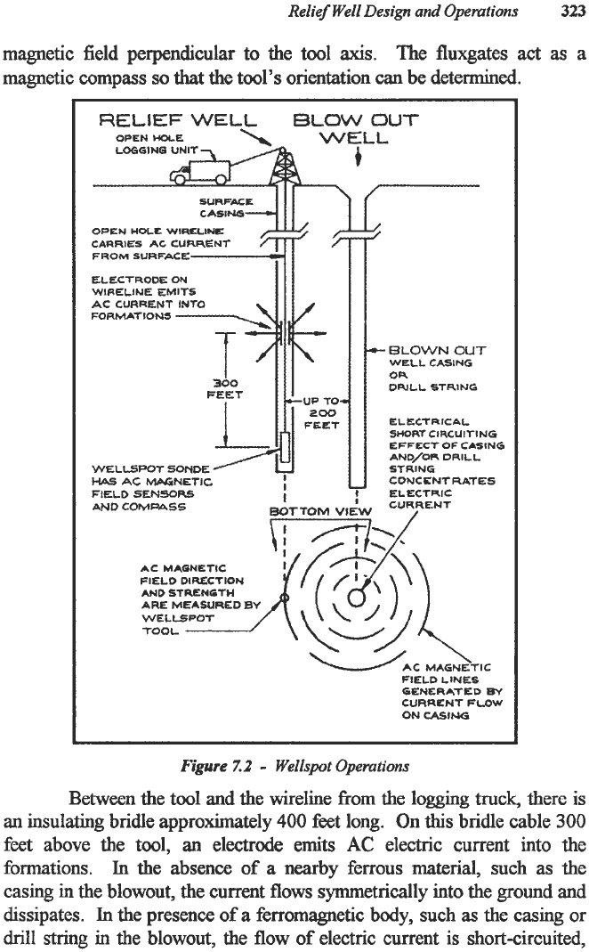
As
illustrated
in
Figure 7.2,
an
electrode is
run
on
a
conventional electric line
300
feet
above
a
tool
consisting of four magnetometers. Two
AC
magnetometers respond to the
two
components
of
an AC magnetic field perpendicular
to
the
axis
of the
tool, and
two
fluxgates measure the
two
components of the
earth’s
Relief
Well
Design
and
Operations
323
magnetic field perpendicular to the tool
axis.
The fluxgates act
as
a
magnetic compass
so
that
the tool’s orientation
can
be determined.
RELIEF
WELL
SLOW
OUT
OPEN
HOLE
OPEN
WOLL
WlRLLlNE
FROM
SURFACE
ELECTRODE
OU
WIRELINE
EMITS
AC
CURRENT
INTO
FORMA7IONS
WE1
HAS
LL51
AC
_.
~~~o
FEET
200
SONDE
MbGNETIC
!
+-
ELOWN
OUT
WELL
CASING
OR
DWLL STRING
ELECTRICAL
SHORT
CIRCUITING
EFFECT
OF
CASING
AND/OR
DRILL
STRING
CONCCNTRATES
ELECTRIC
-
FIELD
5E:NSORS
t
AND
COMPASS
AC MAGNETIC
FIELD
DIRECTION
AND
STREN6TH
ARE
MEASURED
BY
TOOL
WAC
MAGNETIC
FIELD
LINES
OENERATED
By
CURRENT
FLOW
ON
CASING
Figure
7.2
-
Wellspot
Operations
Between the
tool
and the wireline
from
the
logging
truck, there
is
an
insulating bridle approximately 400 feet long. On
this
bridle cable
300
feet
above the tool,
an
electrode
emits
AC
electric current into the
formations.
In the absence of
a
nearby ferrous material, such as
tht:
casing
in
the blowout, the current flows symmetrically into the ground
and
dissipates.
In
the presence
of
a
ferromagnetic body, such
as
the casing or
drill
strjng in the blowout, the flow of electric current is short-circuited,

320
p
300
2
280
P
I
260
l-
v
MAGRANGE
AND WELLSPOT COMPARED
In
June
198
1, Apache Corporation completed the Key
1-1
1
in
the
Upper Morrow at
16,000
feet in eastern Wheeler
County
of the Texas
Par~handle.~ The
Key
1-11
was one of the best wells ever drilled in the
Anadarko basin,
having
90
feet of porosity in excess of
20%.
The
original open flow potential
was
in
excess
of
90
mmscfpd. On Sunday
afternoon,
4
October,
1981,
after being shut in for
78
days waiting on
pipeline connection, the well inexplicably erupted.
The
blowout
that
was
hown
as the biggest
in
the history of the state of Texas was controlled on
8 February,
1983
when the Key
3
relief well intercepted the 5-inch liner in
the blowout at
15,941
feet true vertical
depth
(TVD)
-
the deepest
.
I
I
I
I
I
I
I
I
I
1
1
-
3ZO
-
ll
-300
-
X
a
ll
-280
-
x
I
-
260
x.
Itm
-
ll
I
x
x
-
+t-
N
a
x
x
rill.
~
#E*
-
220
-
a
x
I
a==
1
1
1
I
1
I
I
I
I
I
I
I,
200-
240
reo
-2ao
Relief
Well
Design
and
Opemtions
325
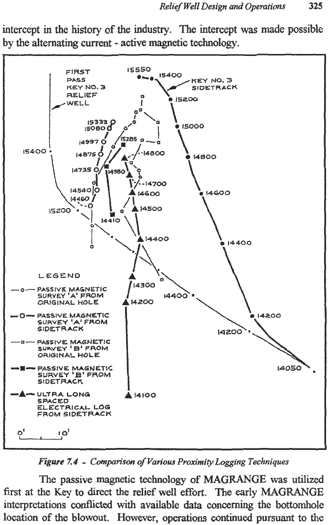
intercept in the
history
of
the industry. The intercept
was
made possible
by the alternating current
-
active magnetic technology.
15400
KEY
NO.
3
lfSfO
15400
FIRST
PASS
KEY
NO.
3
SIDETRACK
'8
15200
RELIEF
'\
/WELL
0
'A.
LEGEND
-0-
PASSIVE
MAGNETIC
SURVEY
'A'
FROM
ORIGINAL
HOLE
-0-
PASSIVE
MAGNETIC
SURVEY
'A'
FROM
SIDETRACK
-0-
PASSIVE
MAGNETIC
SURVEY
'
E'
FROM
ORIGINAL
HOLE
-8-
PASSIVE.
MAGNETIC
SURVEY
'B'
FROM
SIDETRACK
L
14300
4800
-A-
ULTRA
LONG
-
14100
SPACED
ELECTRICAL
LOG
FROM
SIDETRACK
b
15000
\
14800
\
0
14600
\
8
14400
'O\
14400
~
Figure
Z4
-
Comprison
of
Various
Proximity
Logging Techniques
The passive magnetic
technology
of
MAGRANGE
was utilized
first
at
the Key
to
direct the relief well effort. The early
MAGRANGE
interpretations conflicted
with
available
data
concerning the bottomhole
location
of
the blowout. However, operations continued pursuant
to
the