Gasch R., Twele J. (Eds.) Wind Power Plants: Fundamentals, Design, Construction and Operation
Подождите немного. Документ загружается.

6.6 Flow conditions
222
profile. The stress on the single blade is low compared to turbines with a
high tip speed ratio.
Application
- Turbines with a high tip speed ratio are used for electricity generation. Due
to the higher rotational speed of the rotor, a smaller gear transmission ratio
is required compared to turbines with a low tip speed ratio. The small start-
up torque of turbines with a high tip speed ratio is not a problem as the
generator only starts working at higher rotational speeds.
- Turbines with a low tip speed ratio deliver a high torque at start-up and are
suitable for machines, such as piston or heat pumps, sawmills or corn
mills.
6.6.2 Flow conditions in a turbine with a low design tip speed ratio
In order to reach a better understanding of the characteristic curves of a turbine
with a low tip speed ratio, the flow conditions at the blade are discussed with the
following Figs. 6-11 and 6-12. Again, a turbine with a tip speed ratio of
D
= 1 is
used as an example. The turbine has 21 blades dimensioned according to Schmitz
theory.
0.9 R
0.6 R
0.3 R
all r at
α
A
λ
= 2.8
λ
= 1.0
0.3 R
0.6 R 0.9 R
λ
= 0.2
c
L
c
D
2.5
2.0
1.5
1.0
0.5
0.0
-0.5
0 10 20 30 40 50 60 70 80 90
c
L
, c
D
0.9 R
0.6 R
0.3 R
all r at
α
A
λ
= 2.8
λ
= 1.0
0.3 R
0.6 R 0.9 R
λ
= 0.2
c
L
c
D
2.5
2.0
1.5
1.0
0.5
0.0
-0.5
0 10 20 30 40 50 60 70 80 90
c
L
, c
D
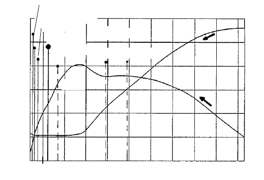
Fig. 6-11 Change of operating points on the profile characteristics during start-up (turbine with a
low design tip speed ratio,
D
= 1)
6 Calculation of performance characteristics and partial load behaviour
223
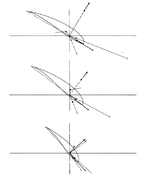
Fig. 6-12 shows three cross sections of the blade: the section above is close to the
outer radius of r = 0.9 R, the one in the middle at r = 0.6 R and the one below
close to the inner radius at r = 0.3 R. The upper half of each displayed section
shows the magnitude and direction of the resulting forces (i.e. sum of lift and drag
forces) for three different tip speed ratios, while the lower half shows the corre-
sponding relative velocity w at the blade section. In addition, Fig. 6-11 shows the
profile characteristics of the lift and drag coefficient. The operating points that are
considered are marked for each blade section.
The blades were analyzed for three tip speed ratios:
= 0.2 (start-up, dashed
lines),
= 1 (design tip speed ratio, thick line), and
= 2.8 (load-free idling, thin
lines). The dimensionless characteristic curves of this turbine were discussed in
section 6.4, Figs. 6-5 to 6-7. They were obtained with the extended calculation
method of section 6.8, where consideration was given to fluid dynamic effects
(blocking of the stream tube) and losses (e.g. profile drag and reduced flow deflec-
tion). The calculation was performed for the case that the wind speed is constant
and the rotor accelerates from standstill to load-free idling.
Plane of rotation
Plane of rotaion
Plane of rotaion
Velocities
Velocities
Velocities
Forces
Forces
Forces
r = 0.6 R
r = 0.9 R
r = 0.3 R
λ = 1
λ = 0.2
λ = 1
λ = 2.8
λ = 2.8
λ = 1
λ = 0.2
λ = 2.8
λ = 1
λ = 2.8
λ = 2.8
λ = 0.2
λ =
2.8
λ = 1
λ = 1
λ =
0.2
λ = 0.2
λ = 0.2
Plane of rotation
Plane of rotaion
Plane of rotaion
Velocities
Velocities
Velocities
Forces
Forces
Forces
r = 0.6 R
r = 0.9 R
r = 0.3 R
λ = 1
λ = 0.2
λ = 1
λ = 2.8
λ = 2.8
λ = 1
λ = 0.2
λ = 2.8
λ = 1
λ = 2.8
λ = 2.8
λ = 0.2
λ =
2.8
λ = 1
λ = 1
λ =
0.2
λ = 0.2
λ = 0.2
Fig. 6-12 Forces, relative velocity angles and relative velocities at three radial cross sections of a
blade for different tip speed ratios (turbine with a low design tip speed ratio,
D
= 1)
6.6 Flow conditions
224
During start-up (following the curves from the right along the arrows in Fig.
6-11), the inner blade section has already a favourable lift/drag ratio, whereas at
the outer sections the flow is still separated. Nevertheless, the circumferential
forces across the entire blade are almost constant due to the increasing profile
chord length with a larger radius. This produces the high starting torque moment
coefficient of the turbine with a low tip speed ratio in Fig. 6-6.
For the design point, design tip speed ratio of
D
= 1, there is along the entire
blade an angle of attack of
A
= 2° with maximum lift/drag ratio as the blade was
designed for this operating point. The circumferential force is somewhat larger at
the outer sections than close to the inner radius due to the larger local circumferen-
tial speed and profile chord length.
When idling, the flow at the blade shows negative angles of attack (
A
< 0) due
to the increased circumferential speed. As a result, the lift coefficient becomes
very small or is even negative. This means that the power extracted in the blade
sections of positive lift (which “acts as a turbine”) is used in the sections with
negative lift coefficient (which “acts as a ventilator”) to actively accelerate the air.
If the turbine ran even faster, strongly negative lift coefficients would be reached
at the outer radius. This explains why the thrust forces of turbines with a low tip
speed ratio are so small during load-free idling.
6.6.3 Flow conditions in a turbine with a high design tip speed
ratio
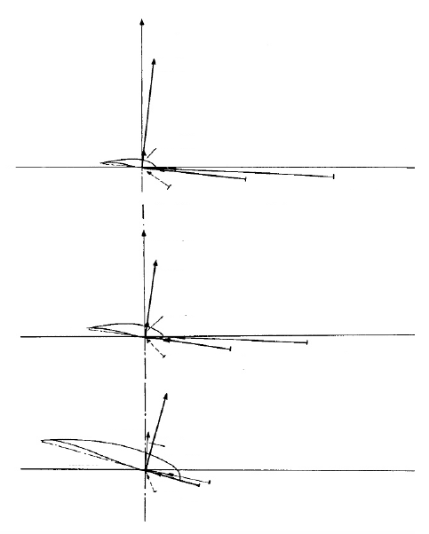
The blade of a turbine with a high tip speed ratio can now be analyzed in the same
way. The turbine we will here consider has a design tip speed ratio of
D
= 7 and
is equipped with three blades which were dimensioned according to Schmitz
theory. Therefore, the profile chord length decreases as the radius increases, Fig.
6-14. As the product of design tip speed ratio and number of blades
D
z = 21 is
equal to that of the turbine with a low tip speed ratio, the blade chord can be
directly obtained from the blade chord diagram, Fig. 5-22.
The blade sections in Fig. 6-14 are drawn using the same scaling factor as for
the blade of the turbine with the low tip speed ratio (Fig. 6-12). The upper blade
section is again close to the outer radius of r = 0.9 R, the blade section in the
middle at r = 0.6 R, and the lower at r = 0.3 R. The upper half of the section shows
the values and directions of the resulting forces, but for these forces, as well as for
the relative velocities in the lower half of the section, a larger scaling factor had to
be chosen than for the turbine with a low tip speed ratio.
The forces were calculated for both wind turbines using the same wind speed.
The profile characteristics, Fig. 6-13, are the same as for to that of the turbine with
the low tip speed ratio since the same aerodynamic profile is used, which makes
more sense for the turbine with the high tip speed ratio. The dimensionless charac-
teristic curves of this turbine were discussed in section 6.3, Figs. 6-2 to 6-4.
6 Calculation of performance characteristics and partial load behaviour
225
0.3 R
0.6 R
0.9 R
all r at
λ = 1.5
0.9R 0.6R 0.3R
c
L
c
D
2.5
2.0
1.5
1.0
0.5
0.0
-0.5
0 10 20 30 40 50 60 70 80 90 α
A
c
L
,c
D
λ = 7.0
λ = 13.5
0.3 R
0.6 R
0.9 R
all r at
λ = 1.5
0.9R 0.6R 0.3R
c
L
c
D
2.5
2.0
1.5
1.0
0.5
0.0
-0.5
0 10 20 30 40 50 60 70 80 90 α
A
c
L
,c
D
λ = 7.0
λ = 13.5
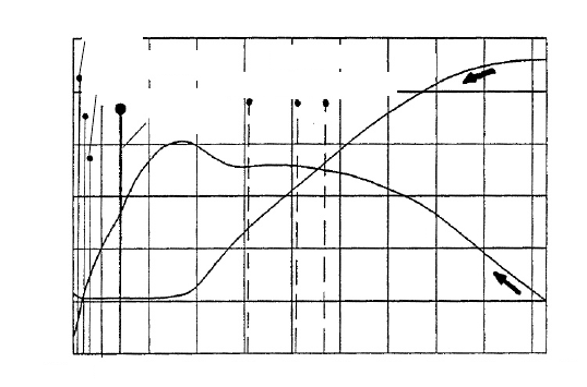
Fig. 6-13 Change of operating points along the profile characteristics during start-up (turbine
with a high design tip speed ratio,
D
= 7)
The blade sections are analyzed now at constant wind speed for the three tip speed
ratios:
= 1.5 (start-up, dashed lines),
= 7 (design tip speed ratio, thick line),
and
= 13.5 (load-free idling, thin lines), Figs. 6-13 and 6-14.
During start-up, we again follow the arrows from the right in Fig. 6-13. Large
parts of the blade are in the same range (i.e. the region of separated flow) of the
profile curve as for the blade of the turbine with a low tip speed ratio, but now the
inner section is also operating here. The values of the forces, Fig. 6-14, are nearly
equal to those of the turbine with a low tip speed ratio, but their direction is less
favourable so it produces only small start-up torque, cf. Fig. 6-3. As the turbine
with a low tip speed ratio has seven times more blades, the thrust forces are sub-
stantially higher for the same blade loading, cf. Figs. 6-7 and 6-4.
When operating at the design tip speed ratio, the angle of attack is again at 2°
along the entire radius as the blade was designed for this operation point. The
circumferential force along the blade is nearly constant. The thrust force at the de-
sign point is equal to the one of the turbine with a low tip speed ratio, approx. 8/9,
cf. Figs. 6-7 and 6-4.
At load-free idling, the angles of attack are slightly negative, Fig. 6-13. The lift
coefficient at the outer radius does not diminish as much as that of a turbine with a
low tip speed ratio. Due to the very high relative velocities which are nearly paral-
lel to the plane of rotation, cf. Fig. 6-14, the forces increase substantially and act
nearly parallel to the rotor axis producing very high thrust, cf. Fig. 6-4. The wind
speed v
2
in the plane of rotation is strongly decelerated compared to the cases of
start-up and design point where it has the same value as the undisturbed wind
speed v
1
.
6.7 Behaviour of turbines with high tip speed ratio and blade pitching
226
λ =
1.5
Velocities
Velocities
Velocities
Forces
Forces
Forces
Plane of rotation
Plane of rotation
Plane of rotation
=
=
l = 7
λ = 7
λ = 7
λ = 1.5
λ = 1.5
λ = 1.5
λ = 1.5
λ = 1.5
λ = 7
λ = 7
λ = 7
λ = 13.5
λ = 13.5
λ = 13.5
λ = 13.5
λ = 13.5
l = 13.5
r = 0.6 R
r = 0.9 R
r = 0.3 R
λ =
1.5
Velocities
Velocities
Velocities
Forces
Forces
Forces
Plane of rotation
Plane of rotation
Plane of rotation
=
=
l = 7
λ = 7
λ = 7
λ = 1.5
λ = 1.5
λ = 1.5
λ = 1.5
λ = 1.5
λ = 7
λ = 7
λ = 7
λ = 13.5
λ = 13.5
λ = 13.5
λ = 13.5
λ = 13.5
l = 13.5
r = 0.6 R
r = 0.9 R
r = 0.3 R
λ =
1.5
Velocities
Velocities
Velocities
Forces
Forces
Forces
Plane of rotation
Plane of rotation
Plane of rotation
=
=
l = 7
λ = 7
λ = 7
λ = 1.5
λ = 1.5
λ = 1.5
λ = 1.5
λ = 1.5
λ = 7
λ = 7
λ = 7
λ = 13.5
λ = 13.5
λ = 13.5
λ = 13.5
λ = 13.5
l = 13.5
r = 0.6 R
r = 0.9 R
r = 0.3 R
Fig. 6-14 Forces, relative velocity direction and velocities at three radial cross sections of a
blade for three different tip speed ratios (turbine with a high design tip speed ratio,
D
= 7)
6.7 Behaviour of turbines with high tip speed ratio and blade
pitching
Blade pitching changes the blade twist angle globally over the blade length. In the
following, “pitching” means pitching the blade to feather position, i.e. the trailing
edge turns out of the wind and the nose of the profile into the wind. The inflow
conditions at a turbine with a high tip speed ratio then become e.g. for the start-up,
more similar to the inflow at a turbine with a low tip speed ratio. However, the
high driving forces of a turbine with a low tip speed ratio are not achieved, since
the blade chords of the turbine with a high tip speed ratio are designed for higher
relative velocities. Nevertheless, the turbine now has an improved self-starting
behaviour, see Fig. 6-16.
6 Calculation of performance characteristics and partial load behaviour
227
Pitching the blade is also useful when the rated power is reached since it reduces
the angle of attack and consequently the lift coefficients, leading to a power limi-
tation, see Fig. 6-15.
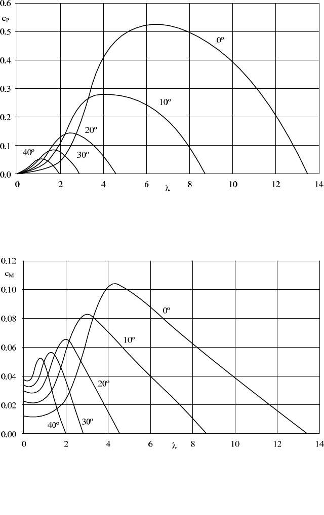
Fig. 6-15 Power coefficient c
P
versus tip speed ratio for different pitch angles (
D
= 7)
Fig. 6-16 Torque moment coefficient c
M
versus tip speed ratio for different pitch angles
6.7 Behaviour of turbines with high tip speed ratio and blade pitching
228
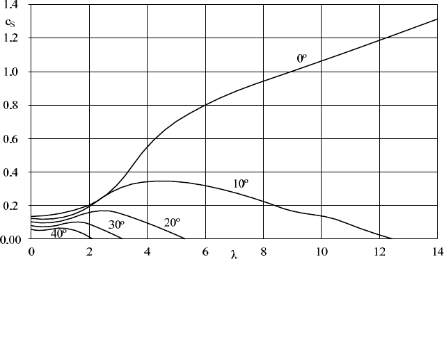
Fig. 6-17 Thrust coefficient c
T
versus tip speed ratio for different pitch angles
So, in turbines with a high tip speed ratio, blade pitching is used for improved
start-up, for power control and also serves as an emergency brake. This will be
discussed in mire detail in chapter 12.
Figs. 6-15 to 6-17 show that with an increasing pitch angle:
- The maximum power and torque moment coefficients decrease substan-
tially.
- The idling tip speed ratio decreases.
- The thrust coefficients are heavily reduced.
- The torque moment coefficient during start-up increases.
In the following an example for using pitch control is presented, based on the
dimensionless characteristics of Figs. 6-15 to 6-17.
Given data:
- Turbine with a high tip speed ratio of
D
= 7,
- Rotor diameter of D = 4 m,
- Rated rotor speed of n
R
= 300 rpm and
- Rated rotor power P
R
= 4 kW.
By pitching the blade, the rotor speed shall be kept constant at n
R
= 300 rpm. The
rated power of the variable speed generator is 4 kW.
We start by determining the factor k
dyn
which allows us to make a simplified
calculation of the dynamic pressure:

6 Calculation of performance characteristics and partial load behaviour
229
mkgRk /85.7
2
2
dyn
a) wind speed v
1
= 10 m/s.
Tip speed ratio at n = 300 rpm:
3.6
30
11
v
R
n
v
R
From the power coefficient curve, Fig. 6-15, we obtain the power coefficient for
the pitch angle of 0°:
c
P
(
= 6.3) = 0.52
Power:
kWWcvAP 452.0100085.7
P
3
1
At this wind speed, action of the pitch control is unnecessary.
b) The wind speed increases to 12 m/s.
Tip speed ratio at n = 300 rpm:
3.5
30
11
v
R
n
v
R
For the pitch angle of 0° this leads to a new c
P
of:
c
P
(
= 5.3) = 0.50
Power:
kWWcvkP 3.65.0172885.7
P
3
1
dyn
However, the generator should draw only 4 kW of power from the rotor to prevent
overload. What does this mean for the required c
P
?
29.0
4
3
1
dyn
P.demand
vk
kW
c

6.7 Behaviour of turbines with high tip speed ratio and blade pitching
230
If there is no pitch control but we leave the pitch angle at 0°, the rotor would
accelerate and therefore increase the tip speed ratio until the power coefficient of
c
P.demand
= 0.29 is reached. This would occur at
=11. What would then be the
corresponding rotational speed?
R
nrpm
R
n
v
2630
30
1
At this rotational speed, the generator would be destroyed (it will shed its wind-
ings and then burn out), that is if the blades have not already been torn off (the
centrifugal forces for blades turning at 630 rpm are 4.4 times higher than at 300
rpm).
But when pitching the blade to feather by 10°, we reduce the angle of attack
and the corresponding lift coefficient. Consequently, we can attain the
c
p.demand
= 0.29 for
= 5.3, i.e. with the rated rotational speed.
c) The wind speed continues increasing to v
1
= 14 m/s; the pitch angle is 10°.
Tip speed ratio at n = 300 rpm:
5.4
30
11
v
R
n
v
R
c
P
(
= 4.5) = 0.29
Power:
kWWcvkP 2.629.0274485.7
P
3
1
dyn
Required c
P
for P = P
R
:
18.0
4
3
1
dyn
P.demand
vk
kW
c
This means the pitch angle must be further increased to approximately 15°.
The pitch angle must be adjusted quickly otherwise the rotor may overspeed and
the generator burn. Moreover, all blades need to be pitched simultaneously to pre-
vent aerodynamic imbalances.
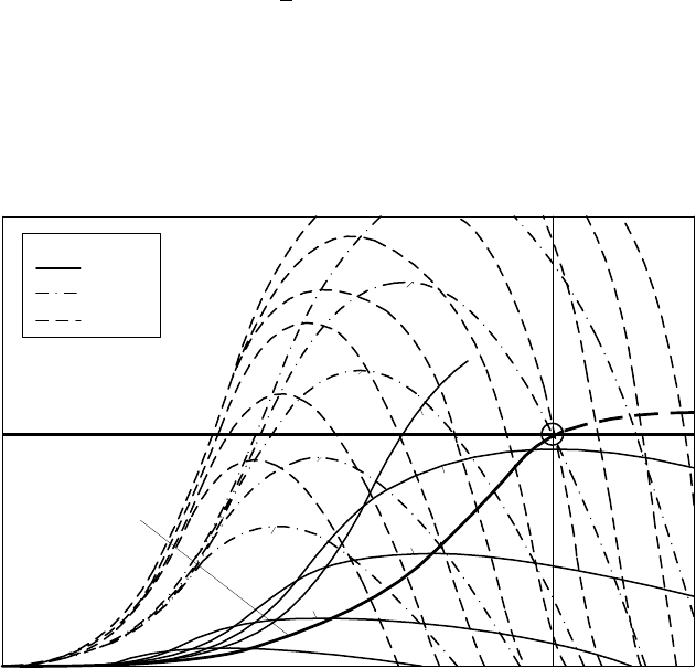
Fig. 6-18 shows the characteristics of a pitch-controlled wind turbine for the
pitch angles 0° (i.e. design blade twist angle), 22.5° and 39.8°. The generator load
6 Calculation of performance characteristics and partial load behaviour
231
curve of the speed-variable wind turbine is shown as well. In the normal wind
range between 4 and approx. 10 m/s the pitch angle remains constant at the design
value of
= 0° (cf. Fig. 12-2) and the wind turbine extracts always the optimum
(i.e. maximum possible) power from the wind. The rotor speed is variable and the
optimum is adjusted according to the current wind speed.
Above the rated wind speed v > 10.3 m/s, i.e. the strong wind range, blade
pitching starts to limit the power to rated power (as indicated by the circle drawn
at the rated operating point (n
R
, P
R
)). It also keeps constant the rotational speed n
R
of the turbine. The curves for constant wind speeds of 22 m/s (pitch angle 22.5°)
and 30 m/s (pitch angle 39.8°) are shown here; these pass through the rated operat-
ing point of (n
R
, P
R
). In general the wind turbines are shut down for wind speeds
exceeding 25 m/s. More details on the blade pitching are found in chapters 12 and
13.
Pitch angle γ
0º
22.5º
39.8º
Generator load curve
Power
P
rated
Rotational speed n
rated
16
20
22
24
26
28
18
20
22
12
10
8
6
30
32
34
36
v = 4m/s
Fig. 6-18 Rotor power versus rotational speed (P-n characteristics) for different pitch angles and
wind speeds of a pitch-controlled wind turbine with a speed variable generator load
6.8 Extending the calculation method
In section 6.1, by equating aerodynamic lift force and aerodynamic force calcu-
lated from the principal of linear momentum, the relative velocity angle at a blade