Ferry M. Direct Stripcasting of Metals and Alloys: Processing, Microstructure and Properties
Подождите немного. Документ загружается.

DSC
process
variables
and
cast
strip quality 113
Mould
wear
Mould wear can be a major problem in strip casting, particularly
in
TRC of iron
alloys where the high melting point metal interacts
with
the relatively soft
copper rolls (Zapuskalov
and
Vereschagin
2000).
Mould wear
may
be
defined
as damage to the mould surface via progressive loss of material
due
to the
relative motion between surfaces of the roll and strip.
It
is
an
inherently
complex process which accompanies both removal of material from the mould
surface
and
a redistribution of topography
on
the surface; this can result
in
progressive roughening of the surface over a period of casting.
Melt
_Strip
_Roll
!
(a)
Roll
Melting
(b)
Roll
Skidding
(c)
Strip Digging
(d)
Strip Slipping
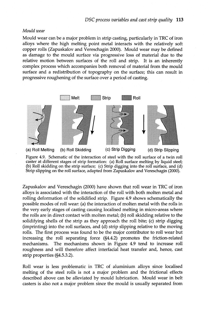
Figure
4.9.
Schematic
of
the interaction
of
steel with the roll surface
of
a twin roll
caster at different stages
of
strip formation:
(a)
Roll
surface melting by liquid
steel;
(b)
Roll
skidding on the strip surface;
(c)
Strip digging into the roll surface, and
(d)
Strip slipping on the roll surface, adapted from Zapuskalov and Vereschagin
(2000).
Zapuskalov and Vereschagin
(2000)
have shown
that
roll
wear
in
TRC of iron
alloys is associated with the interaction of the roll
with
both
molten metal and
rolling deformation of the solidified strip. Figure
4.9
shows schematically the
possible modes of roll wear:
(a)
the interaction of molten metal
with
the rolls in
the very early stages of casting causing localised melting
in
micro-areas where
the rolls are
in
direct contact with molten metal; (b) roll skidding relative to the
solidifying shells of the strip as they approach the roll bite;
(c)
strip digging
(imprinting) into the roll surfaces, and (d) strip slipping relative to the moving
rolls. The first process was found to
be
the major contributor to roll wear
but
increasing the roll separating force
(§4.4.2)
promotes the friction-related
mechanisms. The mechanisms shown
in
Figure
4.9
tend to increase roll
roughness and will therefore affect interfacial heat transfer and, hence, cast
strip properties (§4.5.3.2).
Roll wear is less problematic
in
TRC of aluminium alloys since localised
melting of the steel rolls is not a major problem
and
the frictional effects
described above can
be
alleviated by mould lubrication. Mould wear
in
belt
casters is also
not
a major problem since the mould is usually separated from
114
Direct
strip
casting
of
metals
and
alloys
the solidifying strip
by
both a ceramic-based coating
on
the
mould
surface
and
inert gas interfacial layer (§4.3.2.1).
Mould
deformation
An
important parameter
in
DSC of thin-gauge strip is the strip profile and the
existence of factors such as strip crown, edge
drop
and
thickness variations
in
both the longitudinal
and
transverse directions of the strip (Blejde
et
aI.2000b).
Adequate strip profile is critical for further downstream processing such as
hot
and
cold rolling and may be achieved
by
adequate control of roll gap
dimensions at the nip
and
taking into consideration the strength of the rolls
and their thermal distribution during casting. The overall geometry of the roll
gap
can be adequately maintained
by
machining a roll crown that compensates
for the thermal crown developed during casting. In the 4-Hi TRC casting
configuration shown
in
Figure
3.18,
a designated force can
be
generated in the
backup rolls to adjust the bend (positive
or
negative) of the caster rolls to
ensure that the roll camber is controlled during casting of high quality
thin-
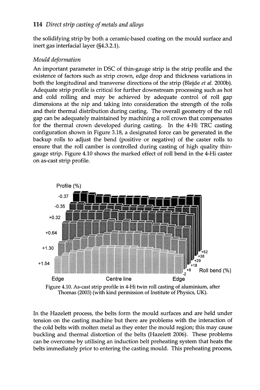
gauge strip. Figure
4.10
shows the marked effect of roll
bend
in
the 4-Hi caster
on
as-cast strip profile.
Profile (%)
+0.64
+1.30
+1.54
Edge
Centre
line
+52
+38
+29
+18
Roll bend (%)
Figure
4.10.
As-cast
strip profile in
4-Hi
twin roll casting
of
aluminium, after
Thomas
(2003)
(with kind permission
of
Institute
of
Physics,
UK).
In
the Hazelett process, the belts form the mould surfaces
and
are held
under
tension
on
the casting machine
but
there are problems
with
the interaction of
the cold belts with molten metal as they enter the mould region; this may cause
buckling and thermal distortion of the belts (Hazelett
2006). These problems
can
be
overcome
by
utilising
an
induction belt preheating system that heats the
belts immediately prior to entering the casting mould. This preheating process,
DSC
process
variables
and
cast
strip quality
115
in
conjunction
with
the belt coatings and inert gas injection, tends to control the
rate of heat transfer during casting and, hence, the as-cast microstructure (see
chapter
5).
Mould
surface
oxidation
Strip casting may continuously contaminate a moving
mould
with
oxides
or
elements from the melt and these have to be minimised
or
removed to maintain
the cleanliness of the cast strip.
In
TRC,
it
is possible to use in-line roll surface
conditioning consisting of brush rolls to remove these
unwanted
films.
4.3.3
Secondary processes
and
processing
During casting, the strip leaves the mould
and
may pass through straightening
(pinch) rolls, various types of furnace
and
one
or
more in-line rolling mills
where
it
is eventually coiled (see Figures
4.1
and
4.2). To ensure continuity of
the process, these secondary stages
must
be
well-controlled using various
control systems. For example,
twin
roll casting of low carbon steel produces
thin-gauge strip
that
passes through
an
inert chamber to prevent scale
formation
and
to control the strip temperature
at
the entry of one
or
more in-
line rolling mills. The rolling mill
must
be configured to take into account the
entry speed of the strip, the desired rolling temperature
and
the degree of
deformation etc. The overall process is therefore similar
in
complexity to a
conventional rolling mill and successful operation relies
on
automated control
systems. After rolling, the strip is usually coiled
in
an
uninterrupted process at
an
appropriate temperature to generate the desired microstructure
and
properties.
4.4 Strip formation
during
DSC
4.4.1
Single rolVbelt casters
In casters of the types shown schematically in Figures 3.16a-c, molten metal is
introduced onto a rotating belt
or
roll to produce the as-cast strip. As indicated
in §3.2.4, these processes have been used extensively
in
the production of
rapidly-quenched ribbons in a continuous manner since the invention
by
Pond
and Maddin
(1969)
of the rotating substrate method for producing amorphous
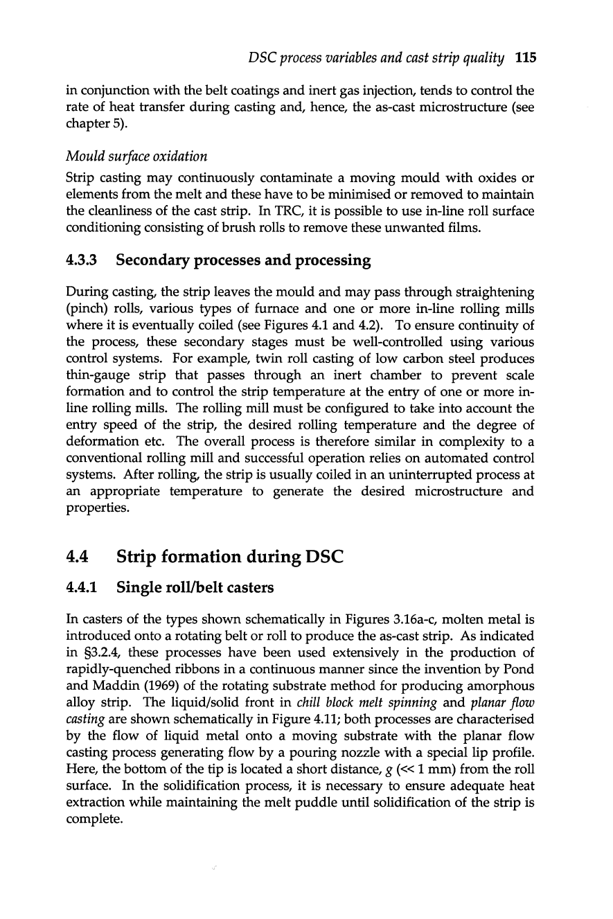
alloy strip. The liquid/solid front
in
chill
block
melt
spinning
and
planar
flow
casting
are shown schematically
in
Figure
4.11;
both processes are characterised
by
the flow of liquid metal onto a moving substrate
with
the planar flow
casting process generating flow
by
a pouring nozzle
with
a special lip profile.
Here, the bottom of the tip is located a short distance,
g
(<<
1 mm) from the roll
surface.
In
the solidification process,
it
is necessary to ensure adequate heat
extraction while maintaining the melt
puddle
until solidification of the strip is
complete.
116
Direct
strip
casting
of
metals
and
alloys
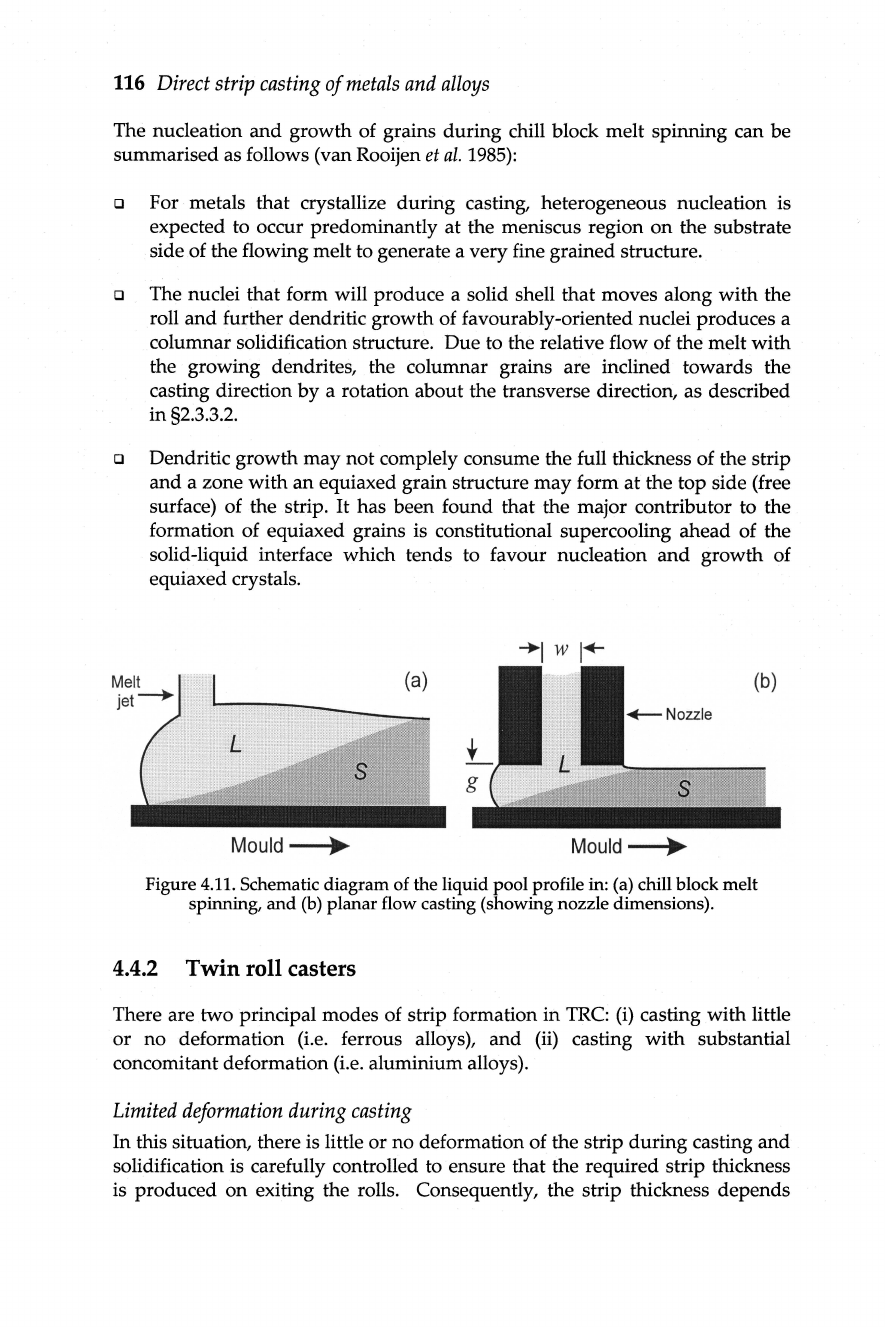
The nucleation
and
growth of grains during chill block melt spinning can be
summarised as follows (van Rooijen
et
al
.
1985):
Q For metals that crystallize
during
casting, heterogeneous nucleation is
expected to occur predominantly
at
the meniscus region
on
the substrate
side of the flowing melt to generate a very fine grained structure.
Q The nuclei that form will produce a solid shell that moves along
with
the
roll
and
further dendritic growth of favourably-oriented nuclei produces a
columnar solidification structure. Due to the relative flow of the melt
with
the growing dendrites, the columnar grains are inclined towards the
casting direction
by
a rotation about the transverse direction, as described
in
§2.3.3.
2.
Q Dendritic growth may
not
complely consume the full thickness of the strip
and
a zone with an equiaxed grain structure may form
at
the top side (free
surface) of the strip.
It
has been found that the major contributor to the
formation of equiaxed grains is constitutional supercooling ahead of the
solid-liquid interface which tends to favour nucleation
and
growth of
equiaxed crystals.
(b)
~Nozzle
s
Mould~
Mould~
Figure 4.
11.
Schematic diagram of the liquid pool profile in: (a) chill block melt
spinning,
and
(b)
planar flow casting (showing nozzle dimensions).
4.4.2 Twin roll casters
There are two principal modes of strip formation in
TRC:
(i)
casting with little
or
no deformation (i.e. ferrous alloys), and
(ii)
casting
with
substantial
concomitant deformation
(Le
. aluminium alloys).
Limited
deformation
during
casting
In
this situation, there is little
or
no deformation of the strip
during
casting
and
solidification is carefully controlled to ensure that the required strip thickness
is produced
on
exiting the rolls. Consequently, the strip thickness depends
DSC
process
variables
and
cast
strip quality
117
principally
on
the thickness of the solidifying shells that form
on
the rolls. Due
to the minimal solid-state deformation, the roll separating forces are
not
excessive
and
the rolls can
be
produced from high conductivity copper sleeves
which ensures a
high
rate of heat transfer from the metal
through
the rolls
(§4.5.3.2). Nevertheless, the casting rolls
must
be designed to withstand
thermal fatigue
and
oxidation
due
to high melt temperatures
and
any roll
deflections that
may
occur during casting (§4.3.2.1).
Roll
ni
p
(
PO
int 2)
Meniscus region
(Point 1)
Figure 4.
12
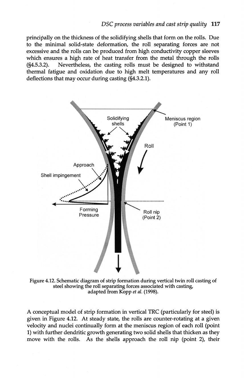
. Schematic diagram of strip formation during vertical twin roll casting of
steel showing the roll separating forces associated with casting,
adapted from Kopp
et
al.
(1998).
A conceptual model of strip formation in vertical TRC (particularly for steel) is
given in Figure 4.
12.
At
steady state, the rolls are counter-rotating
at
a given
velocity
and
nuclei continually form
at
the meniscus region of each roll (point
I)
with
further dendritic growth generating two solid shells that thicken as they
move
with
the rolls. As the shells approach the roll
nip
(point
2),
their
118
Direct
strip
casting
of
metals
and
alloys
dendritic networks interact
and
combine to form the final solidified strip. The
optimum
location of the solidification endpoint for steel strip casting is
different to that for aluminium (see Figure
4.14)
and
is situated just prior to
reaching the bite of the rolls which allows only a very small reduction in
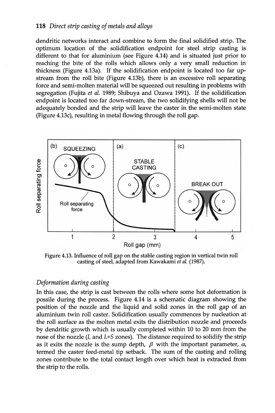
thickness (Figure 4.13a).
If
the solidification endpoint is located too far
up-
stream from the roll bite (Figure 4.13b), there is
an
excessive roll separating
force and semi-molten material will be squeezed
out
resulting in problems
with
segregation (Fujita
et
al.
1989;
Shibuya
and
Ozawa 1991).
If
the solidification
endpoint is located too far down-stream, the two solidifying shells will
not
be
adequately
bonded
and
the strip will leave the caster in the semi-molten state
(Figure 4.13c), resulting in metal flowing through the roll gap.
(b) SQUEEZING
Roll separating
force
2
(a)
STABLE
CASTING
3
Roll gap (mm)
(c)
BREAKOUT
4 5
Figure 4.
13.
Influence of roll gap
on
the stable casting region
in
vertical
twin
roll
casting of steel, adapted from Kawakami
et
al.
(1987).
Deformation
during
casting
In
this case, the strip is cast between the rolls where some
hot
deformation is
possile
during
the process. Figure 4.14 is a schematic diagram showing the
position of the nozzle
and
the liquid
and
solid zones in the roll gap of an
aluminium twin roll caster. Solidification usually commences
by
nucleation
at
the roll surface as the molten metal exits the distribution nozzle
and
proceeds
by
dendritic growth which is usually completed within 10 to
20
mm
from the
nose of the nozzle
(L
and
L+S
zones). The distance required to solidify the strip
as
it
exits the nozzle is the
sump
depth,
f3
with the important parameter, a,
termed the caster feed-metal tip setback. The
sum
of the casting
and
rolling
zones contribute to the total contact length over which heat is extracted from
the strip to the rolls.
DSC
process
variables
and
cast
strip
quality
119
......
f--------a--------I
..
~I
Roll
nip
S+L
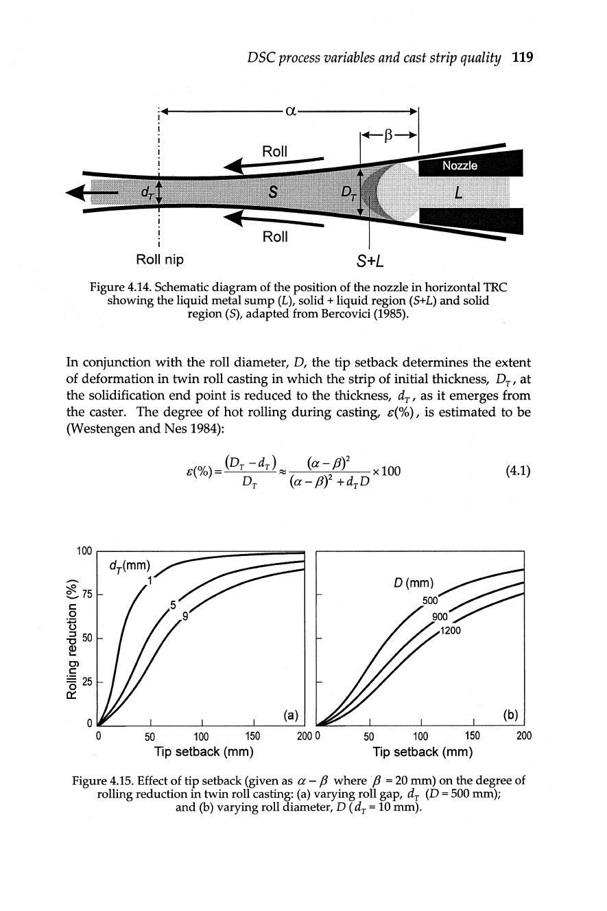
Figure 4.14. Schematic diagram of the position of the nozzle
in
horizontal
TRC
showing the liquid metal
sump
(L), solid + liquid region (5+L)
and
solid
region (5), adapted from Bercovici (1985).
In conjunction with the roll diameter,
D,
the tip setback determines the extent
of deformation in twin roll casting
in
which the strip of initial thickness, D
T
,
at
the solidification
end
point is reduced to the thickness, d
T
,
as it emerges from
the caster. The degree of hot rolling during casting,
e(%) , is estimated to be
(Westengen
and
Nes
1984):
100
1
:-----:::::::::::;;;:===......,
~75
c:
o
n
-5
50
~
Cl
c:
'E
25
0:::
50
100 150
2000
Tip setback (mm)
(4.1)
50
100
150
200
Tip setback (mm)
Figure
4.15.
Effect of tip setback (given as a -
f3
where p =
20
mm)
on
the degree of
rolling reduction
in
twin roll casting:
(a)
varying roll gap, d
T
(D =
500
mm);
and
(b) varying roll diameter, D
(d
T
= 10 mm).
120
Direct
strip
casting
of
metals
and
alloys
Figure 4.15 shows the effect of tip setback
on
the degree of
hot
rolling
during
horizontal TRC
and
the significant influence of roll diameter
and
roll
gap
on
hot
deformation through the roll bite. For the case of TRC of aluminium, the
strip is always solidified
at
a predetermined setback which causes
it
to
be
reduced
in
thickness
by
at
least 20-30% (Merchant
et
ai
.
1989).
Flow stress
.
...
.
....................
·
·········
······
·
··
··
··
···T··
.....
Distance from sump
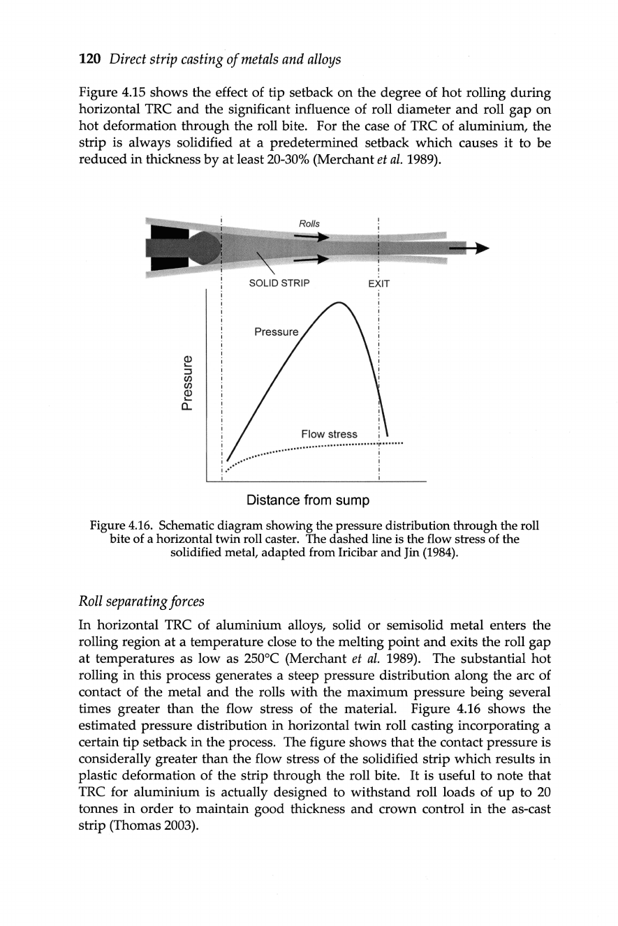
Figure
4.16.
Schematic diagram showing the pressure distribution through the roll
bite of a horizontal twin roll caster. The dashed line is the flow stress of the
solidified metal, adapted from Iricibar
and
Jin
(1984).
Roll
separating
forces
In horizontal TRC of aluminium alloys, solid
or
semisolid metal enters the
rolling region
at
a temperature close to the melting point
and
exits the roll
gap
at
temperatures as low as
250
°C (Merchant
et
ai.
1989). The substantial
hot
rolling
in
this process generates a steep pressure distribution along the arc of
contact of the metal
and
the rolls with the maximum pressure being several
times greater than the flow stress of the material. Figure 4.16 shows the
estimated pressure distribution in horizontal twin roll casting incorporating a
certain tip setback
in
the process. The figure shows
that
the contact pressure is
considerally greater than the flow stress of the solidified strip which results
in
plastic deformation of the strip through the roll bite.
It
is useful to note that
TRC for aluminium is actually designed to withstand roll loads of
up
to
20
tonnes
in
order
to maintain good thickness
and
crown control in the as-cast
strip (Thomas
2003)
.
DSC
process
variables
and
cast
strip quality 121
In
TRC
of steel, the minimal deformation of the solidifying strip results
in
a less
severe pressure hill compared to that generated during aluminium strip
casting. Figure
4.12 shows schematically the increase
in
roll pressure as the
solidifying steel strip passes through the rolls of the caster. There is a moderate
increase
in
pressure
in
the semi-solid zone which increases more sharply on
complete solidification at the roll nip. In this case, the pressure should be
sufficient for the two shells to weld together without too much rolling of the
solidified strip (Kopp
et
al.
1998). The dashed line
in
Figure 4.12 illustrates the
effect of
hot
rolling on the contact pressure where, as expected, a more intense
pressure distribution is generated.
4.4.3
Twin belt and chill block casters
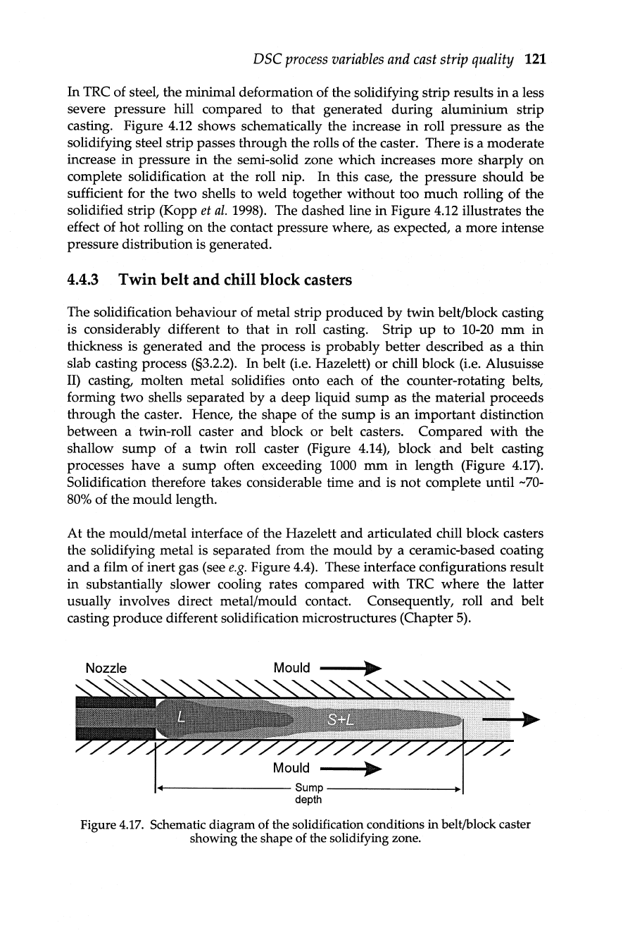
The solidification behaviour of metal strip produced
by
twin belt/block casting
is considerably different to that in roll casting. Strip
up
to 10-20
mm
in
thickness is generated
and
the process is probably better described as a thin
slab casting process (§3.2.2). In belt
(Le.
Hazelett) or chill block (i.e. Alusuisse
II)
casting, molten metal solidifies onto each of the counter-rotating belts,
forming two shells separated
by
a deep liquid sump as the material proceeds
through the caster. Hence, the shape of the sump is
an
important distinction
between a twin-roll caster and block or belt casters. Compared with the
shallow sump of a twin roll caster (Figure
4.14), block
and
belt casting
processes have a
sump
often exceeding 1000
mm
in
length (Figure 4.17).
Solidification therefore takes considerable time and is
not
complete until
-70-
80% of the mould length.
At the mould/metal interface of the Hazelett and articulated chill block casters
the solidifying metal is separated from the mould
by
a ceramic-based coating
and
a film of inert gas (see
e.g.
Figure
4.4).
These interface configurations result
in substantially slower cooling rates compared with TRC where the latter
usually involves direct metal/mould contact. Consequently, roll
and
belt
casting produce different solidification microstructures (Chapter
5).
+----------------Sump--------------~~I
depth
Figure
4.17.
Schematic diagram of the solidification conditions
in
beIt/block caster
showing the shape of the solidifying zone.
122
Direct
strip
casting
of
metals
and
alloys
4.4.4 Influence
of
casting
speed
on
strip
characteristics
4.4.4.1
Liquid
sump
profile
The
mould
speed
during
DSC has a substantial influence
on
the shape of the
liquid metal
sump
(Merchant
et
ai
. 1989). The effect of casting parameters
on
the shape of the
sump
in
horizontal TRC of aluminium alloys has been
modelled
by
Hunt
and
co-workers (Bagshaw
et
ai.
1986; Bradbury
and
Hunt
1995). Their numerical model utilises a generalized energy equation
in
the
liquid, semi-solid
and
solid zones of a
wedge
shaped
moving
mould
and
has
been
used
to investigate the effect of varying casting parameters
on
the thermal
efficiency
of
the process, heat line formation, sticking, segregation
and
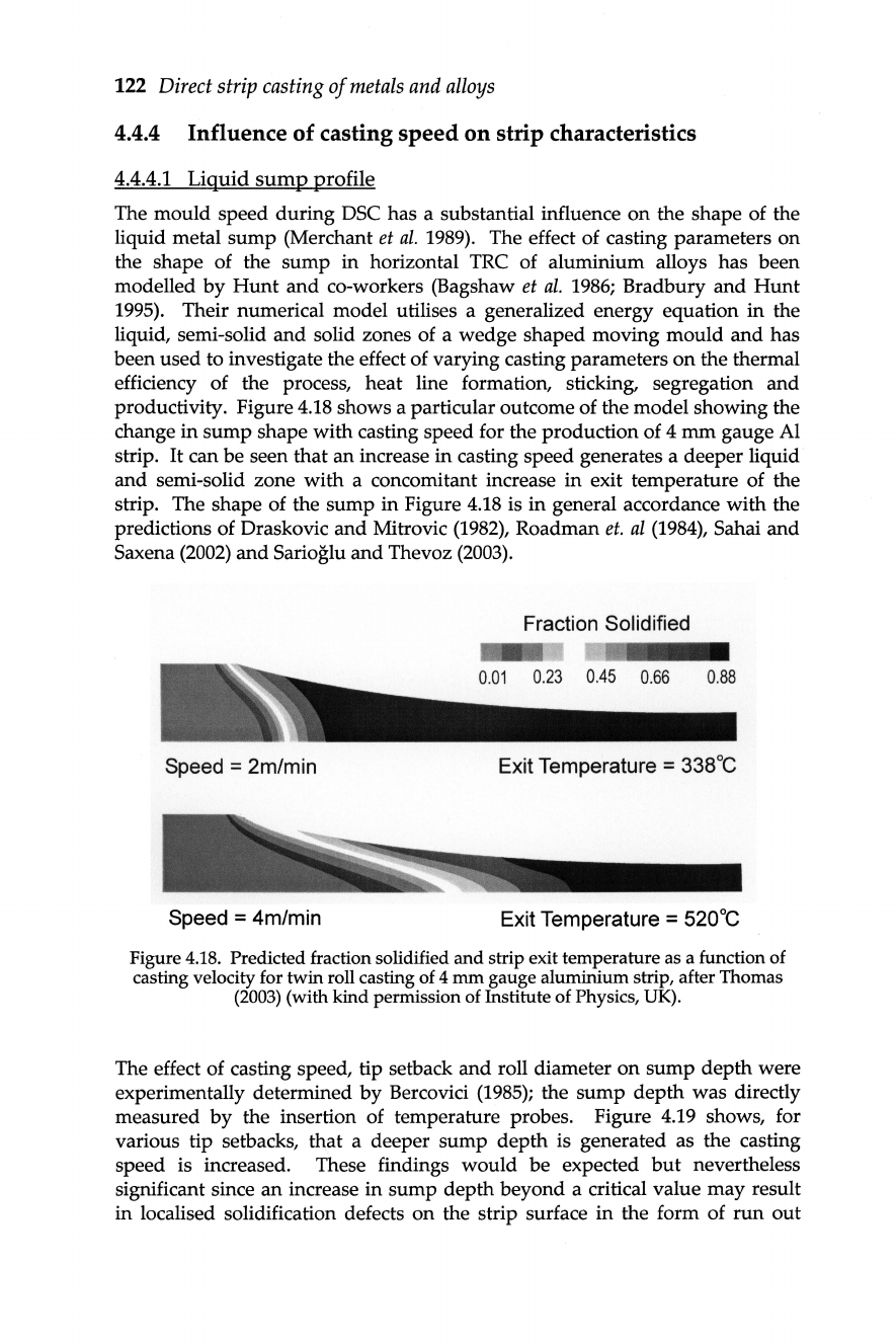
productivity. Figure 4.18 shows a particular outcome of the model showing the
change
in
sump
shape with casting speed for the production of 4
mm
gauge Al
strip.
It
can be seen that
an
increase
in
casting speed generates a deeper liquid
and
semi-solid zone
with
a concomitant increase
in
exit temperature of the
strip. The shape of the
sump
in
Figure 4.18 is
in
general accordance
with
the
predictions of Draskovic
and
Mitrovic (1982), Roadman
et.
ai
(1984), Sahai
and
Saxena
(2002)
and
Sarioglu
and
Thevoz
(2003)
.
Fraction Solidified
Speed
= 2m/min
Exit Temperature = 338°C
Speed
= 4m/min
Exit Temperature
= 520°C
Figure 4.
18.
Predicted fraction solidified
and
strip exit temperature as a function of
casting velocity for twin roll casting of 4
mm
gauge aluminium strip, after Thomas
(2003) (with kind permission of Institute of Physics, UK).
The effect of casting speed, tip setback
and
roll diameter
on
sump
depth
were
experimentally determined
by
Bercovici
(1985);
the
sump
depth
was
directly
measured
by
the insertion of temperature probes. Figure 4.
19
shows, for
various tip setbacks, that a deeper
sump
depth
is generated as the casting
speed is increased. These findings
would
be
expected
but
nevertheless
significant since
an
increase
in
sump
depth
beyond
a critical value
may
result
in
localised solidification defects
on
the strip surface
in
the form of
run
out