Ellis A.M., Feher M., Wright T. Electronic and Photoelectron Spectroscopy: Fundamentals and Case Studies
Подождите немного. Документ загружается.

11 Optical spectroscopy
95
Ionization
limit
Ionization
continuum
Ground
electronic state
Excited
electronic state
hn
hn
hn¢
hn≤
(a) (b)
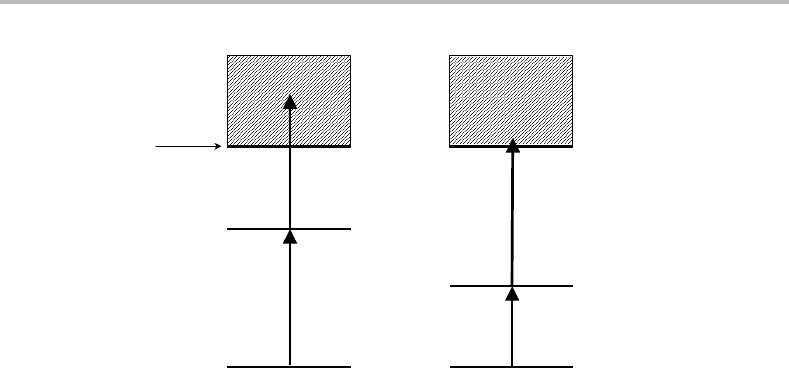
Figure 11.6 (a) One- and (b) two-colour resonance-enhanced multiphoton ionization processes.
therefore has a very low probability. As the wavelength is scanned, when resonance with an
intermediate rovibronic level occurs the ionization probability dramatically increases and
this can be observed by detecting ions. This is the essence of REMPI spectroscopy, namely
the ion current is measured as a function of laser wavelength.
Various experimental arrangements can be used. In the simplest, a single laser is used
to excite both the first and second steps, as shown in Figure 11.6(a). This is known as
single-colour REMPI. However, two pulsed lasers operating at different wavelengths could
be used in a so-called two-colour experiment, one to excite the molecule to the intermediate
electronic state, and the second to produce ionization. The two-colour method is important
when the wavelength required for exciting the resonant transition is unsuitable for the
subsequent ionization step. An example is illustrated in Figure 11.6(b), where the first
photon accesses a relatively low-lying electronic state. Absorption of a second photon from
this laser will not exceed the ionization limit, but a second laser with a much shorter
wavelength can be used to ionize the molecule.
The examples shown in Figure 11.6 use a single photon to access the intermediate state.
The single colour process in this case is sometimes said to be a (1 + 1) process, meaning
one photon of the same wavelength is used in both the first and second excitation steps.
Similarly, the two-colour process is sometimes written as (1 + 1
), the prime indicating
a different colour is being used for the one-photon ionization step. However, it should be
recognized that more than one photon could be used in the initial and ionization steps if
sufficiently intense light sources are employed. For example, (2 + 1), (2 + 1
), (2 +2), and
(3 + 1) processes are not uncommon in REMPI experiments.
Ion formation can be detected by measuring the ion current between two conducting
parallel plates of opposite polarity. Although adequate for many purposes, this approach
is less than ideal for the study of mixtures since REMPI signals from more than one
type of molecule are possible, thus causing potential confusion. A solution to this prob-
lem is to employ a mass spectrometer for detecting the ions, since this allows the mass
of the ion, and therefore the carrier of the spectrum, to be identified. Indeed, this is an

96 Experimental techniques
extremely important advantage REMPI has over LIF spectroscopy. The mass spectrometer
may be a time-of-flight device or a quadrupole mass filter. Further details may be found in
Reference [2].
We have seen that visible or near-ultraviolet photons from powerful pulsed lasers may be
used to access high-lying electronic states by multiphoton transitions. Of course, this is only
possible providing the appropriate selection rules are satisfied. A detailed discussion of the
selection rules, and in particular their derivation, is beyond the scope of this text. However, in
general the selection rules are the result of a sequential application of single-photon selection
rules.
4
Forexample, for linear molecules, for cases where the electronic orbital angular
momentum quantum number, ,isagood quantum number, the one-photon selection rule
is = 0, ±1. However, for a two-photon transition the selection rule becomes = 0,
±1, ±2. Consequently, whereas transitions from a electronic state to a state are
forbidden in single-photon spectroscopy, they are allowed in a two-photon transition. This
often means that new electronic states can be observed by REMPI spectroscopy, and this is
another interesting aspect of this technique.
11.5 Double-resonance spectroscopy
Double-resonance spectroscopy is the study of any spectroscopic transition using two
sequential resonant steps. REMPI could be regarded as an example of double-resonance
spectroscopy. However, whereas the second resonant step in REMPI involves excitation
into the ionization continuum, one could equally well excite an atom or molecule into a
bound state below the ionization continuum. Why would anyone wish to carry out such
an experiment, and how would it actually be done? To some extent the answer to the first
question has already been stated in the previous section describing REMPI spectroscopy.
Any double-resonance absorption transition that uses, for example, two visible photons
induces the same energy change in a molecule as a single photon transition in the ultra-
violet. Ultraviolet light may be difficult to obtain at the desired wavelengths, or it may
be that the linewidth of the ultraviolet source is much higher than that of the visible light
sources used in the optical–optical double-resonance experiment. Another facet of a double-
resonance experiment is the modified selection rules already discussed in the REMPI case.
How would an optical–optical double-resonance experiment be carried out? In general
two lasers are required, both being independently tunable. Care must be taken to ensure
that they overlap spatially and, if they are pulsed lasers, that they also overlap temporally.
Detection of transitions is usually achieved by observing fluorescence (either from the
intermediate state or from the final state), or ions after absorption of a further photon.
The two resonance transitions need not both be ‘upwards’. An important example where
one of the transitions is ‘downwards’is the technique known as stimulated emission pumping
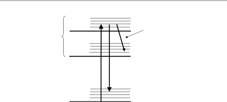
(SEP). This form of spectroscopy is illustrated in the energy level diagram in Figure 11.7.A
photon from one laser, termed the PUMP laser, is used to drive a molecule to a fluorescent
4
We concern ourselves solely with the n-photon resonant step. Selection rules for the ionization step are different
(in fact less stringent) because the departing electron may take away angular momentum.
11 Optical spectroscopy
97
Ground
electronic state
Excited
electronic state
PUMP DUMP
Fluorescence
Figure 11.7 Stimulated emission pumping (SEP) spectroscopy. Two lasers are employed. The PUMP
laser excites the molecule to a particular rovibrational level in an excited electronic state and fluores-
cence from that upper level is monitored. The DUMP laser drives molecules back down to a specific
rovibrational level in the ground electronic state by stimulated emission. A spectrum is obtained
by monitoring the fluorescence intensity as a function of the DUMP laser wavelength; successful
stimulated emission is registered as a dip in the fluorescence intensity.
excited electronic state, and the fluorescence is monitored by a photomultiplier tube. If
a second laser, known as the DUMP laser, is added with the correct frequency to excite
transitions resonantly back down to the lower electronic state, then stimulated emission
can occur. This will necessarily reduce the fluorescence (which is, of course, spontaneous
emission) seen by the PMT since the stimulated emission will follow the path of the DUMP
laser. Thus an SEP spectrum can be recorded by fixing the PUMP laser wavelength, scanning
the DUMP laser wavelength, and recording the dip in fluorescence intensity as a function
of the DUMP laser wavelength.
SEP spectroscopy can be compared with dispersed fluorescence spectroscopy (see
Section 11.2). In the latter, the resolution is limited primarily by the monochromator, and is
often poor. In SEP no monochromator is required and the resolution is limited primarily by
the laser linewidth. The much higher resolution of SEP makes it possible to obtain rotation-
ally resolved emission spectra, and also allows the investigation of very dense vibrational
manifolds in low-lying electronic states such as those seen near to dissociation limits.
11.6 Fourier transform (FT) spectroscopy
The spectroscopic techniques considered so far all work in the frequency domain.Inother
words, the exciting radiation and/or the emitted radiation is selected according to its fre-
quency. A spectrum is then recorded by controlled variation of this frequency.
Fourier transform (FT) spectroscopy adopts a very different approach. It is based on
interference effects produced by radiation of different frequencies. In NMR and microwave
spectroscopy the interference phenomena are observed in the time domain.However, this
is not possible for infrared, visible, and ultraviolet radiation because the frequencies are
98 Experimental techniques
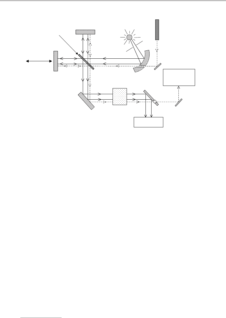
HeNe laser
detector
Detector
HeNe
laser
Continuum
source
Sample
Movable
mirror, M
2
Fixed
mirror, M
1
Beamsplitter, B
Figure 11.8 Schematic of an FT absorption spectrometer, showing the Michelson interferometer at
its heart. The helium–neon laser beam, represented by the dashed line, takes a parallel path to the
light from the continuum source and is used to measure the distance moved by mirror M
2
.
too high. In these regions of the electromagnetic spectrum the length domain is employed
and an interferogram is generated. The interferogram contains information on the complete
spectrum (or at least a large part of it) in an ‘encoded’ form, which can then be converted
into a normal frequency domain spectrum.
The heart of an FT spectrometer is the Michelson interferometer. This is the device that
generates an interferogram. To see how it works, consider the apparatus in Figure 11.8.
Light from a continuum source is passed into the Michelson interferometer and through
a sample cell. However, let us simplify the situation to begin with by imagining that the
light source is monochromatic and that the sample cell is absent. The first part of the inter-
ferometer that the light encounters is the beamsplitter, B, which sends a portion of the
beam towards mirror M
1
and the remainder towards mirror M
2
. After reflection by the
mirrors the two beams return to the beamsplitter and interference takes place. Whether this
interference is constructive or destructive depends on the optical path difference for the
beams in the two arms of the interferometer, i.e. 2BM
1
− 2BM
2
=δ. The quantity δ is
referred to as the retardation.Ifthe retardation is an integer multiple of complete wave-
lengths, i.e. δ =nλ, then constructive interference occurs and the light intensity reaching the
detector will be relatively high. If, on the other hand, δ =nλ/2, then complete destructive
interference occurs and no light reaches the detector. At retardations between these two
extremes, the detector signal level depends on the degree of constructive versus destructive
interference.
5
5
Newcomers to FT spectroscopy and the Michelson interferometer are often troubled by two points. (i) How can
an incoherent light source, such as a lamp, give rise to the phase coherence necessary for observable interference
effects? (ii) Where does the light go when destructive interference occurs if it does not go to the detector? The
answer to question (i) is straightforward. An incoherent light source can be thought of as being composed of
numerous independent waves, or wavelets. Although there is no phase relationship between the wavelets, each
11 Optical spectroscopy
99
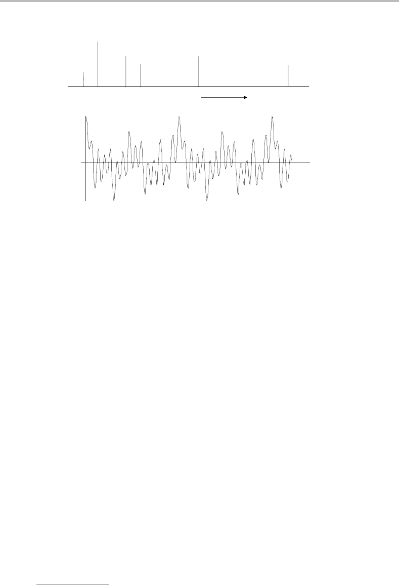
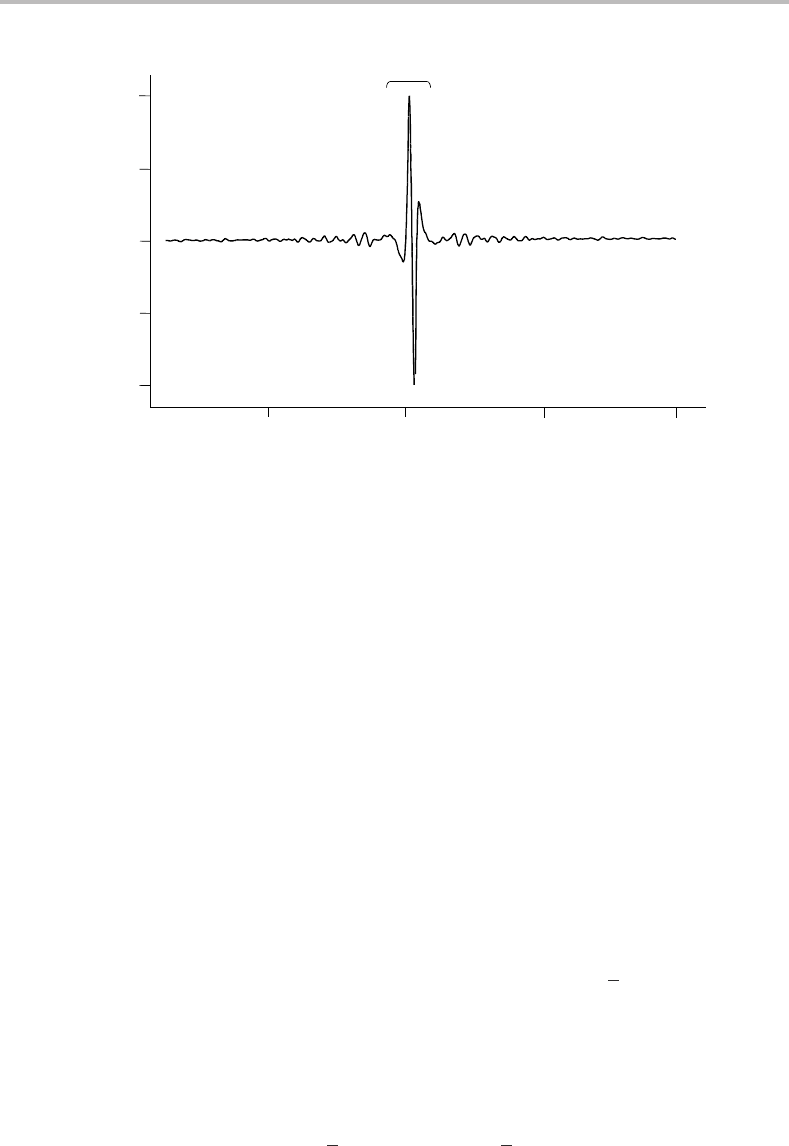
0
d
Signal
Frequency, n
n
2n
4n
5n
9n
15n
(a)
(b)
Figure 11.9 (a) Hypothetical stick spectrum and (b) corresponding interferogram showing the beat
pattern formed by interference of several cosine waves of different frequencies and relative intensities.
The quantity δ is the retardation – see text for further details.
An interferogram is obtained by varying the retardation. This is achieved by moving
one of the mirrors and recording the detector signal as a function of mirror position. For
a monochromatic light source, the interferogram will consist of a single cosine wave and
the wavelength of the light can be measured directly from the interferogram, providing
the retardation is known to sufficient precision at all points in the moving mirror motion.
In order to be able to distinguish peaks from troughs in the waveform, which is clearly
essential for the measurement of the wavelength, the uncertainty in mirror position must be
<λ/2. When dealing with visible or ultraviolet light this is quite a technical challenge but
is feasible and has been achieved.
Figure 11.9 simulates a more complicated situation, where five different radiation fre-
quencies of differing intensities interfere to produce an interferogram. A pattern is still
discernible in this more complicated case but, in the limit of a continuum light source, fully
constructive interference occurs only at δ = 0 and the signal rapidly decays either side of
this position. The strong interferogram at and near δ = 0 shows what is known as a centre
burst.
When an absorbing sample is placed in the spectrometer, a situation somewhat inter-
mediate between the two extreme cases of monochromatic and complete polychromatic
(continuum) radiation sources occurs. The intensity of light entering the interferometer at
certain wavelengths is reduced when the sample is present due to absorption. The result is an
interferogram which is dominated by a centre burst but which also shows interference fringes
extending out from δ =0 (see Figure 11.10). These interference fringes contain, potentially,
all of the information about the absorption by the sample. In other words, it is possible to
extract the complete frequency domain absorption spectrum from the interferogram.
individual wavelet acts as a ‘mini’ coherent light source. Thus the interference effects seen after splitting and
recombining the beam arise from interference of light originating within these individual wavelets. The answer
to (ii) is also straightforward: when there is a drop in intensity at the detector due to interference, this is because
destructive interference redirects the light back towards the source.
100 Experimental techniques
600
0
400
0
1
2
−1
−2
Point number
Detector signal/V
200
Centre burst
Figure 11.10 Interferogram showing a dominant centre burst and the formation of interference fringes
away from the centre burst due to absorption of infrared radiation by the sample. The retardation,
δ,isactually monitored at a series of discrete moving mirror positions given by the ‘point number’ on
the horizontal axis. Zero retardation corresponds to a point number just below 400 in this example.
How might this be done? One route would be a trial and error process, in which we
guessed at the reduction of light intensity at certain wavelengths caused by absorption,
and simulated the interferogram by superimposing the electromagnetic waves at various
values of the retardation. This simulated interferogram would then be compared with the
actual interferogram and, if agreement was not obtained, a new guess would be made at
the absorption spectrum and a new simulation would be attempted. With the help of a
computer this approach is just about conceivable to deduce the frequency domain spectrum
in Figure 11.9(a) from the interferogram in Figure 11.9(b). However, for more complicated
cases, as would be found in real laboratory work, this would be a hopelessly long-winded
process even for a computer.
In practice, the length → frequency domain conversion is achieved by the mathematical
transformation process known as Fourier transformation.Fourier transformation allows
information in one domain to be converted to that in an inverse domain. In the case of
the Michelson interferometer, the interferogram is measured in the length domain, i.e. as a
function of the retardation. The inverse of length is the wavenumber (
v), and so wavenumber
and length are complementary Fourier variables. In other words, if the light intensity at the
detector is measured as a function of retardation, Fourier transformation can convert this
into intensity versus wavenumber, i.e. into a spectrum.
Fourier transformation is an integral transformation given by
I (
ν) = 2
∞
0
I (δ) cos(2πνδ)dδ (11.5)

11 Optical spectroscopy
101
where I(δ)isthe interferogram signal and I(ν)isthe spectrum. This compact expression
may mislead the reader into thinking it is easy to evaluate. However, I(δ)isnot an analytical
function and so the integral must be evaluated numerically. Furthermore, the integral must
be calculated at each value of
ν in order to construct a spectrum. Thus Fourier transformation
is a major computational task and, in the early days of FT spectroscopy, it was a severely
limiting factor. Nowadays, with much higher computer speeds coupled with development
of the fast Fourier transform algorithm in the mid 1960s [3], Fourier transformation rarely
takes more than a few seconds on a high performance PC.
FT spectrometers have a much greater light-gathering power than grating instruments
because both entrance and exit slits are eliminated. Consequently, a spectrum of signal-to-
noise ratio comparable to that of a grating spectrometer can be obtained in a much shorter
measurement time with an FT spectrometer.
Another important advantage of FT spectroscopy is the high accuracy of wavenumber
measurements. The accuracy of the wavenumber measurement is determined, in principle,
by the accuracy with which the moving mirror position is known at all points in its motion.
In real FT spectrometers, the relative position of mirror M
2
relative to M
1
is also measured
interferometrically. This is achieved by sending a reference laser beam, usually from a low
power helium–neon laser (λ = 632.8 nm) along the same path as the signal beam (see
Figure 11.8). The moving mirror generates interference fringes from the laser beam beyond
the beamsplitter and, if the wavenumber of the laser is accurately known, then the relative
position of the mirror is easily deduced by fringe counting (this is done electronically).
Absolute wavenumber accuracies of better than 0.001 cm
−1
are possible.
The final point to note about FT spectroscopy is the resolution. It turns out that the
wavenumber resolution is the inverse of the maximum retardation, δ
max
. Thus for a maximum
mirror displacement of 10 cm, which corresponds to a maximum retardation of 20 cm, a
resolution of 0.05 cm
−1
is obtained The highest resolution commercial instruments currently
on the market have a maximum mirror displacement of about 1 m, giving a best resolution
of 0.005 cm
−1
.
Fourier transform spectroscopy is commonplace in the infrared region. Its extension into
the visible and ultraviolet came later but there are now several commercial manufacturers
of UV/Vis FT spectrometers.
References
1. G. Berden, R. Peeters, and G. Meijer, Int. Rev. Phys. Chem. 19 (2000) 565.
2. Lasers and Mass Spectrometry, ed. D. M. Lubman, New York, Oxford University Press,
1990.
3. J. W. Cooley and J. W. Tukey, Math. Comp. 19 (1965) 297.

12
Photoelectron spectroscopy
12.1 Conventional ultraviolet photoelectron spectroscopy
The basic principles of conventional photoelectron spectroscopy were described in
Section 1.1.Torecap, the molecules of interest are illuminated by ultraviolet photons with
sufficient energy to ionize them.
M + hν → M
+
+ e
−
The photon energy must equal or exceed the ionization energy of molecule M in order for
the above process to take place. Ignoring the kinetic energy of the recoiling ion, which is
negligible owing to the large mass disparity between the ion and the electron, the excess
energy from photoionization can appear either as electron kinetic energy, ion internal energy
(vibrational and rotational), or a combination of the two.
From conservation of energy, as summarized in equation (1.2), measurement of the
electron kinetic energy spectrum for a fixed ultraviolet wavelength provides spectroscopic
information on the ion. The ionization energy depends on which electron is being removed,
and thus the most weakly bound will give rise to electrons with the highest kinetic energy
while those more tightly bound will yield lower energy electrons. This gives rise to coarse
band structure, with each band representing a different ionization process. However, each
band contains structure arising from the population of different vibrational and rotational
levels within the particular electronic state of the ion, and this additional structure provides
agreat deal of important information. This structure can only be observed if the resolution
of the electron spectrometer is sufficiently high and, as will be seen shortly, the resolution
in conventional ultraviolet photoelectron spectroscopy is relatively poor.
Most readers will know that highly electropositive elements, such as the alkali and
alkaline earth atoms, have relatively small first ionization energies. Their first ionization
energies mostly fall in the range 4–7 eV because the s electrons in the outer shell are quite
weakly bound to the nucleus. The first ionization energies of the majority of molecules, and
indeed other elements, tend to be higher, usually exceeding 9 eV. Consequently, just to reach
the first ionization limit requires ultraviolet light of wavelengths ≤140 nm, and to access
higher ionic states much shorter wavelengths may be required. These wavelengths fall in
the vacuum ultraviolet, and this is a difficult region in which to generate monochromatic
light with usable intensities. Indeed, this difficulty was not resolved until the early 1960s
through the introduction of noble gas resonance lamp sources.
102

12 Photoelectron spectroscopy
103
In VUV noble gas resonance lamps, a high voltage DC discharge along a capillary tube
1
is
employed to drive noble gas atoms up to excited electronic states. The electronic transition
back to the ground state is then responsible for the radiation. For helium, the principal
emission line is at 21.218 eV (λ = 58.4 nm) and arises from the transition
1
P(1s
1
2p
1
) →
1
S(1s
2
). This line is referred to as the HeIα line, the I signifying emission from neutral
helium and the α designating that this is the first of a series of possible np → 1s transitions.
Other transitions do occur, not only from neutral helium but also He
+
(these are labelled
HeII transitions), but they are normally much weaker than the HeIα line. Other gases can
be used. For example, neon gives two NeI lines, one at 16.671 and the other at 16.848 eV.
However, helium is the most commonly used both because it is cheaper than neon and
because the higher photon energy means that the valence orbitals of most molecules can be
photoionized with the HeIα line.
The electron kinetic energy spectrum is obtained by passing the ejected electrons through
an energy analyser. This analyser is based on an electric or magnetic field, usually the former,
to distinguish the electrons according to their kinetic energies. There are two main analyser
types, retarding field and deflection analysers.
Retarding field devices transmit only those electrons that have energies higher than the
retarding potential, and to obtain a spectrum the retarding potential is scanned. This type
of analyser is rarely used nowadays and we shall discuss it no further.
Deflection analysers, as the name implies, separate electrons by forcing them to follow
different paths according to their velocities. There are a number of different types, including
the parallel plate analyser (this uses an electric field applied between two parallel plates)
and the cylindrical mirror analyser (containing two charged coaxial cylinders). However,
the only one that we will discuss in any detail is the hemispherical analyser, since it is simple
to understand and is widely used.
The basic geometry of the hemispherical analyser is illustrated in the overall schematic of
a photoelectron spectrometer in Figure 12.1. The name derives from the use of two concentric
hemispherical electrodes, both charged to a potential with the same magnitude but opposite
signs; the inner one is positive and the outer negative. The entrance and exit to the analyser
are restricted by slits that define the range of acceptable entrance and exit trajectories of the
electrons. Electrons that pass through the entrance slits after photoionization may traverse
the analyser and out through the exit slits only by following a specific curved path, but
they will do so only if they have the correct energy (determined by the selected voltages
on the hemispheres). The fate of electrons with higher or lower kinetic energies is clear
from the figure; the electric field is either too weak or too strong, respectively, to allow them
to follow the correct trajectory and they are lost in collisions with the walls. An electron
kinetic energy spectrum is obtained by measuring the electron current at the detector as a
function of the voltage applied to the hemispheres. The voltage can be used to calculate the
electron kinetic energy.
2
1
The capillary serves two purposes. First it helps to collimate the radiation. Second, it helps to minimize the amount
of sample gas passing into the discharge region, since there are no suitable window materials for wavelengths
shorter than 100 nm.
2
In practice one cannot extract a particularly accurate electron kinetic energy by calculations based solely on the
applied voltage. This is because the electron energy also depends on the local charges on any surfaces it passes,

104 Experimental techniques
Figure 12.1 Schematic of a photoelectron spectrometer with a hemispherical electrostatic electron
energy analyser. Electrons of the correct energy traverse the path shown between the charged hemi-
spherical plates. Electrons at higher or lower energies will either strike the walls of the plates or the
exit slits and are not detected. A spectrum is recorded by varying the potential difference between the
plates.
The electrons from the analyser are usually detected by electron multipliers. These are
devices coated with a material which, when hit by an electron, produce secondary electron
emission (typically two or three electrons per incident electron). They thus serve as electron
amplifiers and, when placed in series so that the secondary electrons from one are accelerated
into the next, can produce amplifications in excess of 10
7
. The actual electron current
produced after amplification may still be small but it can be measured with picoammeters
or other sensitive current-measuring devices.
A photoelectron spectrometer must be kept under vacuum and indeed the quality of the
vacuum is crucial. A typical spectrometer will have at least three separate pumping regions,
the resonance lamp, the sample chamber, and the analyser chamber (see Figure 12.1). The
pressure of the sample must be sufficiently high for it to be detectable, but at the same time
it must be low enough to allow the great majority of electrons to escape unimpeded into the
analyser. The usual compromise is a pressure of 10
−4
–10
−5
mbar. The analyser chamber
must be kept at a considerably lower pressure since the electrons must travel much further
in this chamber than in the ionization chamber. Thus pressures of <10
−5
mbar are typically
required there.
and any contamination on the inner walls of the spectrometer always has some effect of this type. Consequently,
the energy scale is established by mixing the desired sample with one or more calibrants of known ionization
energy.