Drake G.W.F. (editor) Handbook of Atomic, Molecular, and Optical Physics
Подождите немного. Документ загружается.

628 Part C Molecules
Table 42.2 Approximate tuning ranges for tunable lasers, cont.
Laser Wavelengths (nm) Notes
Color Centers: (F2+)/LiF 800–1040 cw: laser, Ar, Kr
/NaF 900–1050 cw: laser, Ar, Kr
/KCl:Tl 1400–1700 cw: laser, Ar, Kr, Nd/YA G
/KF 1300–1400 cw: laser, Ar, Kr, Nd/YAG
/NaCl 1400 –1600 cw: laser, Ar, Kr, Nd/YAG
/KCl 1600 –1700 cw: laser, Ar, Kr, Nd/YAG
/KBr 1700 –1900 cw: laser, Ar, Kr, Nd/YAG
/KCl:Li 2500–2900 cw: laser, Ar, Kr, Nd/YA G
/KCl:Na 1600 –1950 cw: laser, Ar, Kr, Nd/YA G
42.3 Interaction of Laser Light with Matter
42.3.1 Linear Absorption
The absorption cross section σ
fi
for transition to the fi-
nal state | f , when integrated over frequency ν,isgiven
theoretically by the leading first-order perturbation of
the initial state |i in the electric dipole approxima-
tion
σ
fi
(ν) dν =4π
2
α
¯
ν
f|
e
r
e
·
ˆ
|i
2
, (42.26)
where the sum is over all charges e at distances r
e
,
ˆ
is a unit polarization vector, and
¯
ν is the av-
eraged transition energy. Averaged over orientations
and summed over possible final states, each elec-
tron contributes to the total integrated absorption cross
section one electron oscillator, πr
0
c ≈ 0.03 cm
2
s
−1
;
here, r
0
is the classical electron radius. Electronic ab-
sorption bands typically contain an oscillator strength
f = 0.01–0.5 of an “electron oscillator”, while weaker
vibrational transitions have f = 10
−6
–10
−4
in each
band.
For narrow lines with radiation of broader band
width ∆ν at flux density J, the linear absorption rate
constant can be usefully estimated as (πr
0
c) fJ/∆ν.
42.3.2 Multiphoton Absorption
Second-order perturbation theory gives the theoretical
two-photon contribution to the absorption. An absorp-
tion cross section σ
(2)
J
1
for a photon of frequency ν
2
is
induced by an off-resonance monochromatic field of fre-
quency ν
1
and photon flux density J
1
. When integrated
over the frequency of the second photon, the second-
order cross section can be related to the dipole matrix
elements
σ
(2)
fi
(ν
1
,ν
2
)J
1
dν
2
=
4π
2
α
2
ν
1
¯
ν
2
J
1
×
m
ν
fm
ν
mi
r
fm
r
mi
ν
mi
−ν
1
2
(42.27)
where
r
fm
=f|
e
r
e
·
ˆ
2
|m ,
r
mi
=m|
e
r
e
·
ˆ
1
|i, (42.28)
and the sum is taken over intermediate states |m having
frequencies ν
mi
and ν
fm
for transitions to the initial and
final states. The energy for the overall transition comes
from two photons; hence the two-photon resonance con-
dition ν
fi
= ν
1
+ν
2
. A special case often occurs when
only one radiation frequency is used: then ν
1
= ν
2
,and
two-photon resonance is achieved when the energy of
the transition corresponds to twice the frequency of the
radiation field.
This integrated, induced cross section is roughly
of the order α(πcr
0
)
2
J
1
/(ν
1
¯
ν
2
). Two-photon absorption
becomes comparable to the one-photon absorption with
off-resonance fields on the order of
J
1
≈
ν
1
ν
2
απcr
0
, (42.29)
or about 10
21
photons s
−1
cm
−2
(10
17
Wm
−2
s
−1
for
typical green light).
Part C 42.3

Spectroscopic Techniques: Lasers 42.3 Interaction of Laser Light with Matter 629
Typical dipole-allowed molecular multiphoton ab-
sorption cross sections are ≈ 10
−58
m
4
s for two photons
and 10
−94
m
6
s
2
for three photons.
Multiphoton absorption was one of the first ef-
fects explored with lasers. Two-photon absorption was
first reported for inorganic crystals containing eu-
ropium ions [42.8]. Blue and ultraviolet fluorescence
appeared in the interaction of red ruby laser light with
organic compounds [42.9–12]. Others observed two-
photon absorption directly [42.13, 14]. Selection rules
for multiphoton absorption are summarized by Mc-
Clain [42.15]; recent work is reviewed by Ashfold and
Howe [42.16].
Highly excited states may subsequently ionize in the
intense fields in a multiphoton ionization (MPI) process.
The ionization signal is often detected in a proportional
ionization cell. A low pressure cell containing the vapor
of a transition metal organometallic, such as iron car-
bonyl or ferrocene which photodissociates to give the
metal atom, may be used for wavelength calibration by
MPI.
42.3.3 Level Shifts
High radiation power causes resonant frequencies to
shift, responding to the ac Stark effect [42.17, 18]. Even
moderate fields, tuned near resonance, interact strongly
with an atom or small molecule, which undergoes rapid
excitation and stimulated emission at the characteristic
power dependent Rabi frequency,
ν
Rabi
=
2πg
1
g
1
+g
2
σ
21
J . (42.30)
Fluorescence from such an interacting system has
a characteristic “head and shoulders” spectrum best
understood as radiation at the fundamental frequency
amplitude modulated at the Rabi frequency [42.19].
42.3.4 Hole Burning
Radiation at a particular frequency generally moves pop-
ulation out of states that absorb that radiation. Molecules
that interact resonantly with the radiation may also
spontaneously emit at different frequencies, thereby
ending in nonabsorbing states. This optical pumping
effect can make resonance features in an absorption
spectrum disappear at high power levels [42.20]. De-
pletion may appear as a “hole” in the absorption
spectrum [42.21]. Recently, interest has shifted to per-
manent “hole burning” as a method of information
storage in materials.
Hole burning is the basis for Doppler-free Lamb-
dip spectroscopy, in which only absorbing atoms or
molecules having little or no velocity component along
the axis of two counterpropagating beams are tem-
porarily depleted [42.22]. This technique is commonly
used for laser frequency stabilization, such as with the
iodine-locked He
−
Ne laser.
42.3.5 Nonlinear Optics
Multiplying
Nonlinear susceptibility of an optical medium can gen-
erate radiation at frequencies which are multiples of
the frequency of laser radiation passing through. Phe-
nomenologically, the second order polarization
P
2ν
=
0
χ
[2]
E
2
ν
(42.31)
is given in terms of the second order nonlinear suscep-
tibility χ
[2]
, a third rank tensor, and the electric field at
the fundamental frequency (see Chapt. 72). This nonlin-
ear susceptibility can range from 0.5–5pm/V for typical
materials used for frequency doubling. Typical materials
and their use are reviewed by Bordui and Fejer [42.23].
For a nonlinear process occurring over a length l
in a cylindrical region with Gaussian waist w
0
with
polarization P
0
on axis, the far field flux is given by
J(R,θ)=
π
4
ν
3
n
3
w
4
0
P
2
0
4hc
3
0
R
2
sin
2
[(k
0
−k cos θ)l/2]
(k
0
−k cos θ)
2
×exp
−k
2
w
2
0
sin
2
(θ)/2
. (42.32)
Here, n is the index of refraction and k the propagation
constant for the induced radiation, while k
0
is that for the
induced polarization, the vector sum of those of the orig-
inal radiation. When phase matched, k
0
−k cos θ = 0,
and the term in the brackets maximizes to (l/2)
2
.
The greatest difficulty is in selecting materials which
can be phase matched such that the relative phases of the
fundamental and overtone radiation propagate together
through the material; otherwise radiation at the higher
frequency generated at different places inside the ma-
terial destructively interfere. Phase matching is usually
achieved by either angle tuning of a birefringent crystal,
or by temperature tuning.
Only materials without a center of inversion in their
crystal structures have a second order nonlinear suscep-
tibility. All materials, including gases, will have a third
order nonlinear susceptibility χ
[3]
. This can be used
to generate third harmonics, especially in the vacuum
ultraviolet (VUV), where doubling materials are not
available [42.24, 25].
Part C 42.3

630 Part C Molecules
Mixing
The same materials that permit frequency doubling and
tripling also allow 3-wave and 4-wave frequency mixing.
The frequency matching conditions are, respectively,
ν
1
±ν
2
= ν
3
,
ν
1
±ν
2
±ν
3
= ν
4
. (42.33)
Tunable UV radiation may be generated by adding the
frequencies of a fixed and tunable visible outputs. Tun-
able IR has been obtained by differencing fixed and
tunable visible lasers. Mixing of radiation from an Ar
ion laser with that from a tuned R6G dye laser in lithium
iodate to produce tunable 2200–4600 nm radiation is
noteworthy.
Optical Parametric Oscillator
It is possible to reverse 3-wave mixing, generating two
frequencies whose sum is that of the input radiation. In
parametric generation, the output frequencies are given
by the phase match conditions. Both the desired fre-
quency and the secondary “idler” frequency must be
allowed to build up in the nonlinear medium. The idler
radiation is not present initially, but results from the fre-
quency mixing process itself. The process has many of
the characteristics of a laser oscillator, including that of
a gain threshold. This makes tuning of an optical para-
metric oscillator similar to that of a laser, but with more
degrees of freedom: now oscillation at two frequencies
must be attained simultaneously, along with the correct
phase matching of the nonlinear material [42.26].
42.3.6 Raman Scattering
It is possible to have one or more of the fields in a mixing
process belong to just polarization, rather than radiation.
The frequency additive case of multiphoton absorption
has already been consisdered; the frequency subtractive
case is Raman scattering.
Incoherent Raman Scattering
Radiation at a higher frequency can excite a lower fre-
quency vibration or rotation within a material, with
appearance of radiation at the frequency of the incident
radiation minus that of the absorption. The integrated
cross section for this effect is given by (42.27). However,
in this case the cross section is for emissionof the second
photon. The rate of spontaneous Raman emission is ob-
tained by multiplying (42.27) by the spectral flux density
of the zero-point field, 8πν
2
/
r
c. Typical vibrational Ra-
man cross sections for transparent molecules are about
10
−34
m
2
sr
−1
in the blue–green (488 nm) [42.27].
Alternatively, energy can be extracted from an
excited state, with the inelastically scattered photon de-
parting with the sum of the incident frequency and that of
the deexcitation. The term “anti-Stokes” distinguishes it
from the more usual “Stokes” type of Raman scattering.
Coherent Raman Emission
The integrated cross section for emission stimulated at
the Raman frequency is given directly by (42.27).
A fourth-order mixing process that is less suscepti-
ble to saturation involves coherent anti-Stokes Raman
scattering (CARS). Two beams excite the material: the
difference of their frequencies corresponds to an excita-
tion of the material. Stimulated Raman scattering excites
the material, which then deexcites through an anti-
Stokes process, giving rise to a third, higher frequency
radiation field. The phase is determinate, and the radia-
tion leaves the region of scattering as a beam [42.28].
If the incident radiation induces a Raman process
over a sufficiently long path, the stimulated Raman
process can be used for gain at both the Stokes and
anti-Stokes frequencies. Since spontaneous Raman pro-
cesses are proportional to the integrated cross section,
while gain in the stimulated Raman process is propor-
tional to the peak cross section, simple materials with
sharp, simple line spectra are most suitable for Raman
gain media. While Raman lasers have been produced
using vibrational excitation of organic liquids, currently
the most important technical application is for Raman
shifting the output of lasers, tunable or otherwise, to fre-
quencies which otherwise would be inaccessible. The
high pressure H
2
Raman shifter produces, at low pow-
ers, beams consisting almost entirely of well separated,
sharp lines shifted by 4160 cm
−1
from the pump beam;
at high powers, a series of Stokes and anti-Stokes bands
appear, each separated by 4160 cm
−1
from each other.
42.4 Recent Developments
One of the most exciting advancements in the past
decade in laser physics has been the generation of
optical frequency combs; and, more specifically, their
applicability in the domain of high-resolution laser spec-
Part C 42.4

Spectroscopic Techniques: Lasers References 631
troscopy. Basically, through a superposition process of
many continuous wave modes, a short train of fre-
quency spikes may be produced from a mode-locked
laser [42.29] (see also Sect. 30.1.5). These spikes are
equally spaced and are referred to as a frequency comb.
The frequency ω
n
of the n
th
cavity mode may be ex-
pressed as
ω
n
= nω
r
+ω
, (42.34)
where ω
r
is characteristic of the laser and ω
is a fre-
quency offset due to the difference between the phase
and group velocity of the superposed waves.
The microwave frequencies ω
r
and ω
are deter-
mined through the use of nonlinear optics. Once these
two parameters are determined, any unknown optical
frequency ω
o
may be measured by recording the beat fre-
quency between it and the closest comb frequency. This
technique gives experimenters a high-precision method
for the spectroscopic determination of such fundamen-
tal quantities as the fine structure constant, the Rydberg
constant, and the Lamb shift [42.30, 31].
Text and references updated by Mark M. Cassar
References
42.1 A. Einstein: Phys. Z. 18,121(1917)
42.2 H. Kogelnik, T. Li: Proc. IEEE 54, 1312 (1966)
42.3 J. T. Verdeyen: Laser Electronics, 3rd edn. (Prentice
Hall, Englewood Cliffs 1994)
42.4 O. Svelto: Principles of Lasers (Plenum, New York
1976)
42.5 R. Wallenstein, T. W. Hänsch: Opt. Commun. 14,353
(1975)
42.6 E. P. Ippen, C. V. Shank, A. Dienes: Appl. Phys. Lett.
21,348(1972)
42.7 R. K. Jain, C. P. Ausschnitt: Opt. Lett. 2, 117 (1978)
42.8 W. Kaiser, C. G. B. Garrett: Phys. Rev. Lett. 7, 229
(1961)
42.9 W. L. Peticolas, J. P. Goldsborough, K. E. Rieckhoff:
Phys. Rev. Lett. 10, 4345 (1963)
42.10 W. L. Peticolas, K. E. Reickhoff: J. Chem. Phys. 39,
1347 (1963)
42.11 S. Singh, B. P. Stoicheff: J. Chem. Phys. 38, 2032
(1963)
42.12 S. Z. Weisz, A. B. Zahlen, J. Gilreath, R. C. Jarnagin,
M. Silver: J. Chem. Phys. 41, 3491 (1964)
42.13 J. J. Hopfield, J. M. Warlock, K. Park: Phys. Rev. Lett.
11,414(1963)
42.14 B. Staginnus, D. Frölich, T. Caps: Rev. Sci. Instrum.
39, 1129 (1968)
42.15 W. M. McClain: Acc. Chem. Res. 7,129(1974)
42.16 M. N. Ashfold, J. D. Howe: Ann. Rev. Phys. Chem.
45, 57 (1994)
42.17 H. J. Carmichael, D. F. Walls: J. Phys. B 9, 1199
(1976)
42.18 L.-P. Li, B.-X. Yang, P. M. Johnson: J. Opt. Soc.
Am. 2,748(1985)
42.19 B. R. Mallow: Phys. Rev. 188, 1969 (1969)
42.20 L. J. Rothberg, D. P. Gerrity, V. Vaida: J. Chem. Phys.
75, 4403 (1981)
42.21 S. Völker: Ann. Rev. Phys. Chem. 40, 499 (1989)
42.22 W. R. Bennett Jr.: Phys. Rev. 126, 580 (1962)
42.23 P. F. Bordui, M. F. Martin: Ann. Rev. Mater. Sci. 23,
321 (1993)
42.24 A. Kung: Opt. Lett. 8, 24 (1983)
42.25 J. Bokor, P. Bucksbaum, R. Freeman: Opt. Lett. 8,
217 (1983)
42.26 J. Falk, J. M. Yarbourough, E. O. Ammann: IEEE J.
Quantum Elec. 7,359(1971)
42.27 C. M. Penney, R. L. St. Peters, M. Lapp: J. Opt. Soc.
Am. 64,712(1974)
42.28 P. R. Regnier, J. P. Taran: Appl. Phys. Lett. 23,240
(1973)
42.29 T. Udem, R. Holzwarth, M. Zimmerman, C. Goble,
T. Hänsch: Topics Appl. Phys. 95, 295 (2004)
42.30 J. M. Hensley: A precision measurement of the fine
structure constant. Ph.D. Thesis (Stanford Univer-
sity, Stanford 2001)
42.31 B. de Beauvoir, C. Schwob, O. Acef, L. Jozefowski,
L. Hilico, F. Nez, L. Julien, A. Clairon: Eur. Phys. J.
D 12, 61 (2000)
Part C 42

633
Spectroscopic
43. Spectroscopic Techniques:
Cavity-Enhanced Methods
Cavity enhanced spectroscopy (CES)methodology
provides a much higher degree of sensitivity
than that available from conventional absorption
spectrometers. The aim of this chapter is to
present the fundamentals of the method, and the
various modifications and extensions that have
been developed. In order to set the stage, the
limitations of traditional absorption spectrometers
are first discussed, followed by a description of
cavity ring-down spectroscopy (CRDS), the most
popular CES embodiment. A few other well-known
CES approaches are also described in detail. The
chapter concludes with a discussion of recent work
on extending CRDS to the study of liquids and
solids.
43.1 Limitations
of Traditional Absorption Spectrometers 633
43.2 Cavity Ring-Down Spectroscopy ............ 634
43.2.1 Pulsed Cavity Ring-Down
Spectroscopy ............................ 634
43.2.2 Continuous-Wave Cavity
Ring-Down Spectroscopy
(CW-CRDS) ................................ 635
43.3 Cavity Enhanced Spectroscopy............... 636
43.3.1 Cavity Enhanced Transmission
Spectroscopy (CETS) .................... 637
43.3.2 Locked Cavity Enhanced
Transmission Spectroscopy
(L-CETS).................................... 638
43.4 Extensions to Solids and Liquids ........... 639
References .................................................. 640
43.1 Limitations of Traditional Absorption Spectrometers
An absorption spectrometer measures the difference in
intensity between the incident light intensity I
0
and the
transmitted light intensity I(x,λ). Beer’s law relates the
absorbed light to the sample absorption α(λ)
I(x,λ)= I
0
e
−α(λ)x
, (43.1)
where λ is wavelength, and x is path length. Absorption
is related to concentration C through the extinction coef-
ficient ε(λ) namely α(λ) = Cε(λ). Typically, a spectral
feature, called an absorption peak, of the target species
is measured in order to obtain its concentration. The
performance of a spectrometer has two figures of merit:
sensitivity and selectivity.
Sensitivity is the smallest detectable change in one
centimeter of path length that a spectrometer can meas-
ure during one second. If many measurements can be
made within a second, averaging may be used to further
improve (by a factor of the square root of the number
of measurements or the square root of the data acquisi-
tion rate) the achievable sensitivity. Sensitivity has units
of cm
−1
Hz
−1/2
. Sensitivity can also be quantified us-
ing the minimum detectable absorption loss (MDAL),
i. e., the normalized standard deviation of the small-
est detectable change in absorption (units of cm
−1
).
Equation (43.1) shows that the sensitivity of a spectrom-
eter depends not only on the light path length through
the sample, but also on the intensity noise of the light
source.
Selectivity is the ability of a spectrometer to distin-
guish between two different species absorbing at similar
wavelengths. The instrument must be able to resolve
the different spectral lines. Thus, selectivity depends on
spectral resolution, which has units of frequency (MHz),
wavelength (nm), or wavenumbers (cm
−1
).
Traditional spectrometers, such as non-dispersive in-
frared (NDIR), and Fourier Transform infrared (FTIR),
use incoherent thermal light sources. For both tech-
niques, the physical length of their sample chamber
limits their sensitivity. Some devices try to fold the
light path several times through the sample cham-
ber in order to improve sensitivity, but this approach
encounters physical size and mechanical stability lim-
itations. Typical MDAL are in the 10
−5
cm
−1
range.
These instruments therefore rely on measuring the
strongest absorption transitions available, which are
found in the mid-infrared range (3 to 12 µm). Often,
however, the strongest transitions overlap with features
of other species found in the sample mixture. The in-
strument performance becomes a sensitivity-selectivity
tradeoff.
Part C 43

634 Part C Molecules
Laser-based optical detection methods, called tun-
able diode laser absorption spectroscopy (TDLAS),
circumvent some of these problems by exploiting the co-
herent nature of laser light. A tunable continuous-wave
laser source brings two benefits:
•
A narrow linewidth, which allows high spectral res-
olution scans to be performed, and
•
Low spatial beam divergence, which allows it to be
folded hundreds, if not thousands of times.
By transmitting laser light having a small beam
size over long distances, multi-pass cells can be
designed to achieve up to a kilometer of path
length enhancement. Multi-pass cell laser spec-
troscopy systems have demonstrated MDAL down
to 10
−9
cm
−1
. However, such instruments still re-
main limited by laser intensity fluctuations and
interference fringes. Moreover, standard multi-pass
techniques do not provide an absolute optical loss
measurement.
43.2 Cavity Ring-Down Spectroscopy
Cavity ring-down spectroscopy (CRDS)isamore
recently developed TDLAS approach that replaces
a multi-pass cell with a stable optical resonator, called
the ring-down cavity (RDC). CRDS is based on the prin-
ciple of measuring the rate of decay of light intensity
inside the RDC. The transmitted wave decays exponen-
tially in time. The decay rate is proportional to the total
optical losses inside the RDC.
In a typical CRDS setup, light from a laser is first
injected into the RDC, and is then interrupted. The
circulating light inside the RDC is both scattered and
transmitted by the mirrors on every round-trip, and can
be monitored using a photodetector placed behind one
of the cavity mirrors. The decay constant, also called
the ring-down time τ is then measured as a function of
laser wavelength to obtain a spectrum of the cavity op-
tical losses. Detailed mathematical treatments of CRDS
can be found in [43.1]. A simple derivation is presented
here.
For a given wavelength λ the transmitted light I(t,λ)
from the RDC is given by
I(t,λ)= I
0
e
−
t
τ(λ)
, (43.2)
where I
0
is the transmitted light at the time the light
source is shut off, and τ(λ) is the ring-down time
constant. The total optical loss inside the cavity is
L(λ) =
[
cτ(λ)
]
−1
l
rt
where c is the speed of light. The
total optical loss comprises the empty cavity optical loss
and the sample optical loss. CRDS provides an abso-
lute measurement of these optical losses. The empty
cavity (round-trip) optical loss L
empty
(λ) comprises
the scattering and transmission losses of the mirrors.
In general, better mirrors provide lower empty cavity
losses and higher sensitivity. The sample (round-trip)
optical loss is A(λ) = α(λ)l
rt
where l
rt
is the cavity
round-trip length, and is simply the difference between
total cavity losses and empty cavity losses, namely
A(λ) = L(λ) − L
empty
(λ). Once the absorption spec-
trum α(λ) of the sample has been measured, then the
sample concentration can be readily computed using the
absorption cross section and lineshape parameters.
The MDAL for a CRDS system is defined by
α
min
=
1
l
eff
∆τ
τ
,
(43.3)
where (∆τ/τ) is called the shot-to-shot noise of the sys-
tem. The effective path length of a CRDS measurement
is l
eff
= cτ. For typical RDC mirrors having a reflectivity
of 99.995%, and scattering losses of less than 0.0005%,
the path length enhancement can exceed 20 000. For
a 20 cm long sample cell, the effective path length is
8 km, which exceeds the best performance of multi-pass
spectroscopy by a factor of three, based on effective
path length alone. A good CRDS system can achieve
a shot to shot variation of 0.03%, leading to a MDAL
of 4 × 10
−10
cm
−1
. Note also that the CRDS measure-
ment is not dependent on either the initial intensity of
the light inside the cavity, provided that the signal has
a sufficient signal to noise ratio at the detector, or on the
physical sample path length like traditional absorption
spectroscopy. Moreover, CRDS can use laser sources
having narrow linewidths and achieving high spectral
resolution.
CRDS can resolve all three limitations of absorp-
tion spectroscopy, namely sensitivity, selectivity, and
dependence on intensity noise of the light source [43.1].
CRDS has been implemented using many different ap-
proaches. This chapter will discuss several commonly
used variations on the CRDS technique.
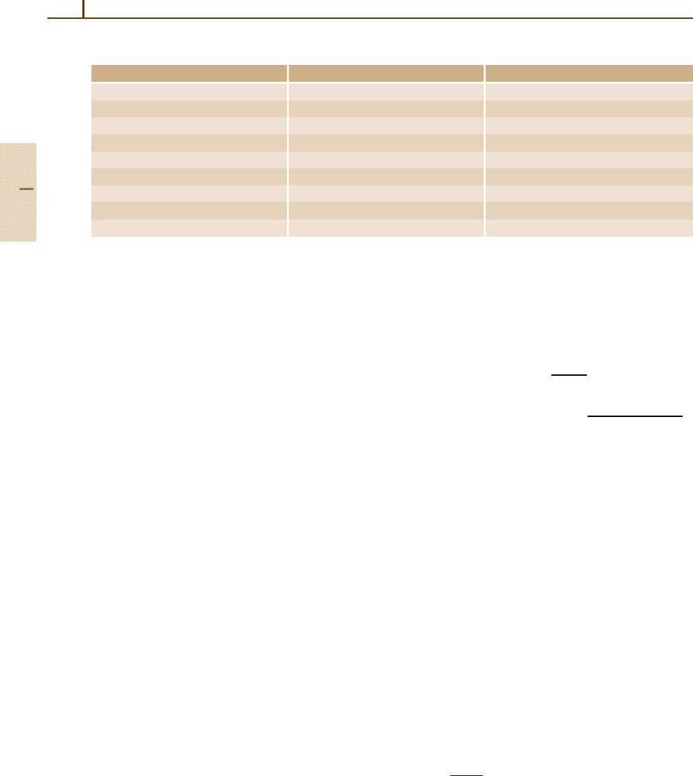
43.2.1 Pulsed Cavity Ring-Down
Spectroscopy
Early implementations of CRDS used pulsed lasers
sources (P-CRDS) [43.2]. A typical P-CRDS setup
Part C 43.2
Spectroscopic Techniques: Cavity-Enhanced Methods 43.2 Cavity Ring-Down Spectroscopy 635
High reflectivity mirrors:
Cavity/ Sample chamber
Pulsed laser
Mode-matching
optics (optional)
Detector
PC
A/D
Converter
Fig. 43.1 Typical P-CRDS setup
is shown in Fig. 43.1. Today, CRDS has been imple-
mented in the broadest possible range of wavelengths,
from the UV (216 nm) to the mid-infrared (10 µm).
Because of its experimental simplicity, P-CRDS has
become a widespread tool for chemists and spectro-
scopists, finding applications in the measurement of
predissociation dynamics, photolysis products, radiative
lifetimes, aerosols or soot detection, temporal imaging,
overtone vibrational spectroscopy, and kinetic studies.
Typical P-CRDS sensitivity is 1 × 10
−9
cm
−1
Hz
−1/2
.
P-CRDS methods have also been combined with
other detection methodologies. Variations on P-CRDS
include:
•
Fourier-transform (FT) P-CRDS [43.3], where an
RDC is excited with a broadband source and time-
resolved FT scans of the RDC output waveform are
taken. Inversion of the interferogram then produces
time-dependent ring-down waveforms at all resolved
frequencies within the source wavelength range.
•
Polarization P-CRDS [43.4], where the spectral
splitting induced by the magnetic field is observed
from the difference of the ring-down spectra of the
two orthogonal polarizations.
•
Pulse-stacked P-CRDS [43.5], where the length of
the RDC is set so that pulses from a very high repe-
tition rate pulsed source coherently add together,
which increases the effective cavity light through-
put to yield improved detection of the ring-down
waveform.
Spectral resolution and sensitivity of P-CRDS are,
however, limited by the use of short-pulse lasers. The
effects of pulsed laser bandwidth on spectral resolu-
tion of P-CRDS have been studied extensively and have
led to system designs where only a single longitudi-
nal and transverse mode of the RDC is excited [43.6].
However, single-mode P-CRDS is difficult to implement
experimentally, and still has limited sensitivity because
the laser pulse is substantially attenuated by the RDC
mirrors at the cavity output. The requirement for im-
proving CRDS sensitivity by reducing the variability in
the measurement of the decay constant from shot to shot
with single-mode excitation, and improving the light
transmission through the cavity to increase the signal to
noise ratio of the decay waveform on the detector, pro-
vided the catalyst to implement continuous wave (CW)
lasers in CRDS.
43.2.2 Continuous-Wave Cavity Ring-Down
Spectroscopy (CW-CRDS)
CW lasers have narrow linewidths (< 50 MHz) and can
be tuned in small spectral increments (< 50 MHz) to
achieve high spectral resolution with excellent wave-
length reproducibility. Moreover, owing to their narrow
linewidths, they are better suited for efficiently coupling
into a single mode of a high finesse RDC, thereby reduc-
ing shot-to-shot variations in measured ring-down decay
constant. Furthermore, they can be directly modulated,
thereby allowing higher data repetition rates, leading in
turn to improved sensitivity.
The first efforts in CW-CRDS involved optically
locking a laser diode to a high-finesse cavity, but the per-
formance was limited because the laser diode would drift
andlocktodifferentRDC modes. The use of sufficient
optical isolation and an external optical switch resolved
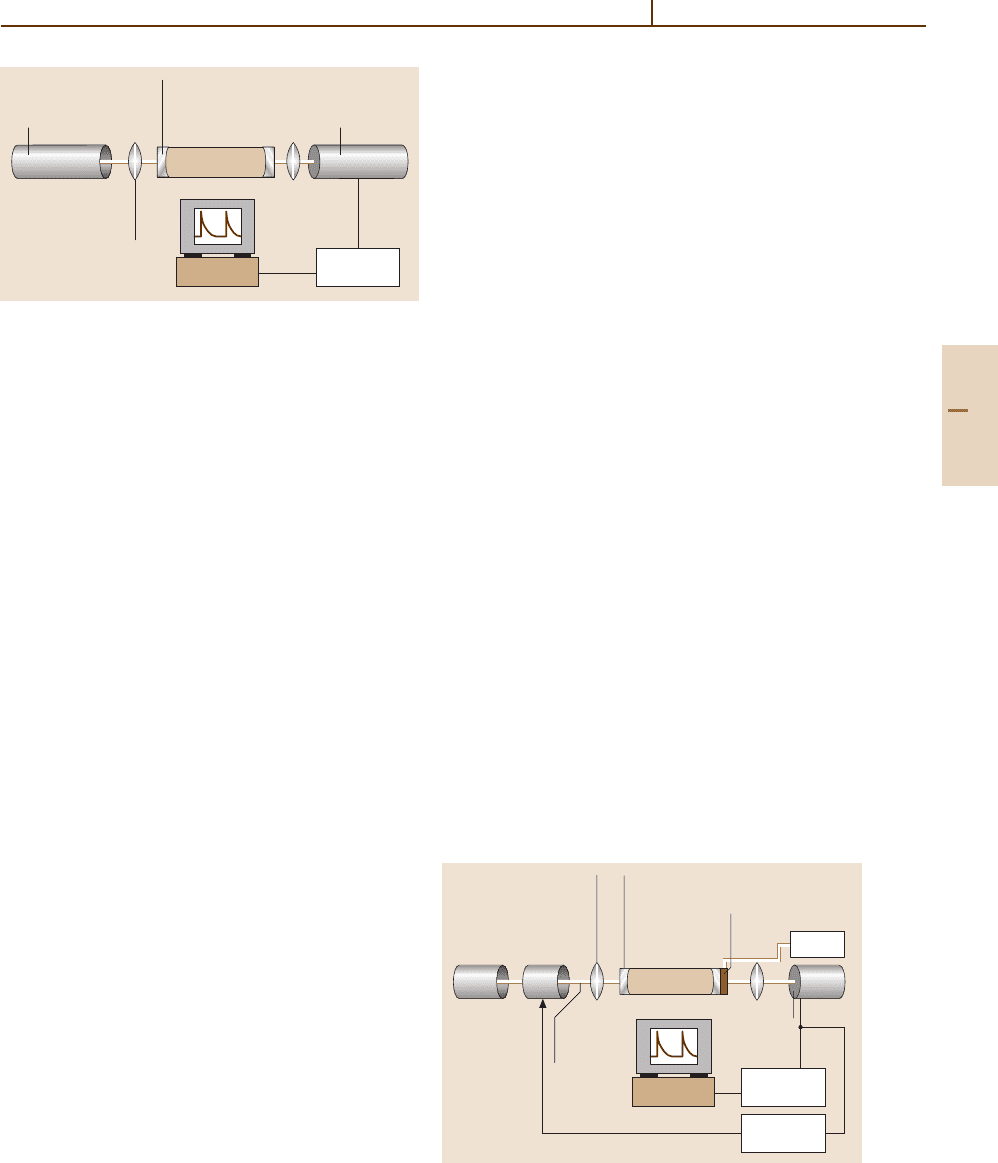
this issue. The most common approach used today is
to sweep a RDC mode through the emission profile of
a diode laser, and shut the laser off with an acousto-optic
modulator (AOM)(Fig.43.2) when sufficient light is in-
jected into the cavity [43.7]. Numerous variations on this
approach exist. For example, CW-CRDS can be imple-
mented by rapidly sweeping the cavity mode into and
High reflectivity mirrors:
Cavity/ Sample chamber
CW laser
Mode-matching
optics (optional)
Detector
PC
A/D
Converter
Driver
AOM
Threshold
trigger
First-order
deflected
beam
PZT actuator
Fig. 43.2 Typical CW-CRDS setup
Part C 43.2

636 Part C Molecules
out of resonance with the laser. The simplest approach
is to sweep the laser wavelength into and out of reson-
ance with a cavity mode and directly modulate the laser
source current [43.8]. The most popular CW lasers used
today are distributed feedback (DFB) diode lasers.
In most CW-CRDS embodiments, the ring-down
cavities are linear, i. e., consist of two mirrors. Ring
resonators (e.g., triangular or bow-tie cavities) can also
be used. Ring cavities provide the benefits of mini-
mizing optical feedback and eliminating the need for
extensive isolation or frequency shifting of the laser
source. Moreover, ring resonators break the frequency
degeneracy between cavity modes having orthogonal po-
larizations, effectively creating two coupled resonators
having high and low finesse, respectively. The low fi-
nesse cavity can be used to lock the laser to a single
cavity mode, while the high finesse cavity can be used
for CRDS.TheAOM acts as both a frequency-shifter
and an on-off switch. This method was used to demon-
strate the highest CRDS sensitivity achieved to date,
namely 1.0×10
−12
cm
−1
Hz
−1/2
[43.9].
Prism-based, rather than mirror-based cavities
have also been used [43.10]. Such cavities comprise
two prisms whose intra-cavity facing angles are at
Brewster’s angle, and whose extra-cavity facing angles
are such that total internal reflection occurs, and results
in unit reflectivity. One of the prisms has a curved facet
to create a stable optical resonator. The purpose of this
design is to extend operation over a much broader range
of wavelengths than can be achieved using dielectric
coatings. Currently, high reflectivity mirrors are limited
in bandwidth to about ±15% of their center wavelength.
CW-CRDS has been applied over a wide range of
wavelengths. It has been used for medical breath an-
alysis, trace gas detection in environmental and process
control applications, and isotopic analysis. In the near-
infrared, CW-CRDS systems achieve sensitivities of
10
−11
cm
−1
Hz
−1/2
, and a concentration measurement
repeatability of 1 part in 5000. Similar performance
in the mid-infrared (3 µm) resulted in the detection of
parts-per-trillion ethylene concentrations [43.11].
Extensions of the basic CW-CRDS technique have
also been developed:
•
Phase-shifted CW-CRDS [43.12]: the phase shift
accrued by a sinusoidally modulated CW laser is
measured for both an empty RDC and one having
a sample. The concentration is deduced from these
two measurements.
•
Heterodyne CW-CRDS [43.13]: enhances the power
in the ring-down decay waveform by mixing with
a local oscillator. For example, the local oscillator
can be the orthogonal polarization used to lock the
laser to the RDC, or can be the reflected signal from
the RDC when laser is frequency-shifted (by the
local oscillator frequency) off resonance from the
RDC mode. Heterodyne CRDS can approach the
shot-noise limit.
•
V-cavity CW-CRDS [43.14]: a three-mirror V-
shaped RDC is exploited to achieve consistent
repetitive optical locking of a DFB diode laser to
a single cavity mode, thereby significantly enhan-
cing light throughput.
CW-CRDS is now maturing to a level of robust-
ness and reliability that it can be commercially deployed
in industrial applications, where the sensitivity require-
ments can no longer be met by FTIR, NDIR,orgas
chromatography.
43.3 Cavity Enhanced Spectroscopy
Most CRDS systems capture the ring-down waveform
using a digital oscilloscope. The Levenberg–Marquardt
(LM) method produces the optimal fit, so that LM
methods have become the de facto “gold standard” in
CRDS [43.15]. However, the LM algorithm can require
multiple iterations, thereby limiting the data acquisition
times to several hundred Hz. Fast-fitting algorithms that
closely approximate the LM fit, but allow data acquisi-
tion rates up to 10 kHz have recently gained widespread
deployment [43.16]. Today, the data acquisition rates are
no longer limited by the back-end numerical fit. Rather,
the speed of CRDS systems is limited by the speed of
laser modulation itself.
Cavity enhanced spectroscopy (CES) was developed
in an effort to simplify CRDS and eliminate the require-
ment for digitization of a time-domain signal and laser
modulation. CES has many different implementations.
All CES methods are based on the principle that the build
up of intracavity power, and hence cavity throughput, de-
pends on intracavity losses, which include absorption by
a sample. CES involves measuring the steady-state trans-
mission through a cavity as a function of wavelength
in order to determine changes in integrated transmitted
intensity caused by the absorbing species.
For a cavity having two mirrors of intensity re-
flectivity, R, and length, L, the effective steady-state
Part C 43.3

Spectroscopic Techniques: Cavity-Enhanced Methods 43.3 Cavity Enhanced Spectroscopy 637
path length is L
eff
= L/(1 − R). If an absorbing gas
is present, the reflectivity will be “reduced” by the
Beer–Lambert factor e
−αL
namely R
= Re
−αL
so that
one can effectively relate the ratio R
/R to the Beer–
Lambert ratio I/I
0
for a single pass. The steady state
transmitted laser intensity for such a cavity is given by
I = I
L
C
p
T
[
2(1 − R)
]
−1
where T is the intensity trans-
missivity I
L
is the laser intensity, and C
p
is the coupling
efficiency in the cavity mode. Thus, for an absorbing gas,
the change in transmitted intensity at a given wavelength
is:
∆I/I = GA
(
1 + GA
)
−1
, (43.4)
where A = 1 − e
−αL
and G = R/(1 − R) so that for
αL 1, (∆I/I) ≈ GA≈ GαL. This latter relation has
been interpreted as a linear response in absorption loss,
multiplied by an effective cavity “gain” of R/(1 − R),
i. e., the absorbance is measured over the effective length
of the cavity which corresponds to the number of cav-
ity passes occurring within the cavity ring-down time
constant. Note that the transmitted power level will
be attenuated by the mirror transmissivity, T,sothat
these methods are limited by laser power and detector
sensitivity.
Because CES techniques measure transmitted light
intensity, they are no longer immune to laser intensity
noise. Furthermore, when the absorbance becomes com-
parable to the cavity loss, the sensitivity improvement of
CES saturates, as the sample absorption begins to domi-
nate the effective number of cavity passes. Note that for
this case, the effective path length becomes a function
of the sample concentration, which underlines another
limitation of CES: this technique is not independent of
the cavity length and hence depends on cavity align-
ment. Moreover, CES systems are not self-calibrated
to the species extinction coefficient, and therefore re-
quire calibration against a known sample concentration,
or against the absolute cavity loss, often measured us-
ing CRDS. Finally, it should be noted that the rate of
data collection in CES is limited by the RDC time con-
stant, because the cavity acts like a single-pole, low pass
filter having a 3 dB frequency of (2πτ)
−1
which can
range from 5 to 50 kHz. Unlike CRDS, CES does not re-
quire fast digitization of the decay waveform followed
by a non-linear fit, so that the data acquisition hardware
can be a much slower, less expensive A/D converter and
spectral data can be acquired almost instantaneously.
Five distinguishable variants of CES have been
developed and are discussed. The first three
methods, called cavity enhanced transmission spec-
troscopy (CETS), find their origins in CRDS.These
methods are cavity enhanced absorption spectroscopy
(CEAS) [43.17], integrated cavity output spectroscopy
(ICOS) [43.18], and off-axis ICOS [43.19]. For these
three approaches, the laser intensity is no longer inter-
rupted to observe a “ring-down event”, although the
path length enhancing properties of the RDC remain.
More sensitive CES methods involve locking the laser
to the cavity mode resonance. These will be referred to as
locked cavity enhanced transmission spectroscopy and
have two variations: locked cavity enhanced transmis-
sion spectroscopy (L-CETS) [43.20] and noise-immune,
cavity-enhanced optical heterodyne molecular spec-
troscopy (NICE-OHMS) [43.21].
43.3.1 Cavity Enhanced Transmission
Spectroscopy (CETS)
CETS has been implemented using several variations,
all of which are based on measuring the time-integrated
transmission through a high finesse RDC as function of
wavelength. As stated earlier, the transmitted light pro-
vides an effectively enhanced path length to any sample
absorption inside the cavity. The transmitted light inten-
sity in all CETS approaches is a small fraction [about
(1 − R)] of the incident intensity, which reduces the
signal to noise on detection, so that averaging is re-
quired. All CETS approaches are also dependent on laser
intensity noise and sample path length.
The trade-off in using a high finesse cavity is that in
steady state, its transmission is a non-uniform function
of wavelength, and consists of a series of sharp cav-
ity mode peaks, namely the transverse and longitudinal
modes. This transmission pattern repeats itself periodic-
ally every free spectral range (FSR). The density of the
mode spacing is a function of the cavity design: round-
trip length and mirror radius of curvature. The quality
of mode matching between the laser and the RDC deter-
mines the number of modes into which light can couple
efficiently.
CEAS is the simplest CETS approach: the laser,
coupled through a RDC, is tuned in wavelength over
the absorption feature of interest, and the integrated
cavity transmission is measured as a function of wave-
length [43.17]. The cavity length is free-running (neither
modulated nor locked to the laser). In order to minimize
the non-uniformity of cavity transmission, CEAS ex-
ploits cavity geometries such that the inherent mode
structure is as dense as possible. No mode-matching is
employed, so that laser light is coupled into as many
modes as possible. The laser is scanned multiple times
over the cavity modes in order to time average over
Part C 43.3
638 Part C Molecules
the unstabilized cavity length. Extensive averaging can
be required to achieve reasonable performance. The
residual mode structure of the cavity can be significant
and produces intensity modulation in the spectrum. Typ-
ically, the laser linewidth is larger than the individual
cavity mode resonances, so that the output can be very
noisy. CEAS does appear to have mechanical stability
advantages, in that a cavity length change or deforma-
tion is in fact desirable to randomize the excited modes
over wavelength. Typical sensitivities of CEAS range
from are 5 × 10
−7
cm
−1
Hz
−1/2
.
ICOS tries to achieve uniform transmission through
the RDC by systematically disrupting the cavity
mode resonances, in order to recover the frequency-
averaged response of the cavity as a function of
wavelength [43.18]. RDC length modulation was im-
plemented by either moving one of the cavity mirrors
using a piezo-electric transducer (PZT), or by slightly
modulating the angle of injection in the cavity using
a PZT-driven mirror mount. When the laser is scanned
over the desired wavelength range with only the RDC
modulation sweeping the modes (5 to 10 free spectral
ranges), the resulting absorption spectra show an inten-
sity modulation of about 10%. This intensity modulation
results from a periodic non-uniformity in the mirror
movement at the turning points of the PZT modulation,
where the increased overlap time between the cavity
mode and laser produces a higher transmitted light in-
tensity. In order to eliminate this intensity modulation,
the laser wavelength is frequency modulated simultane-
ously. The typical sensitivity of ICOS approach is about
2×10
−7
cm
−1
Hz
−1/2
.
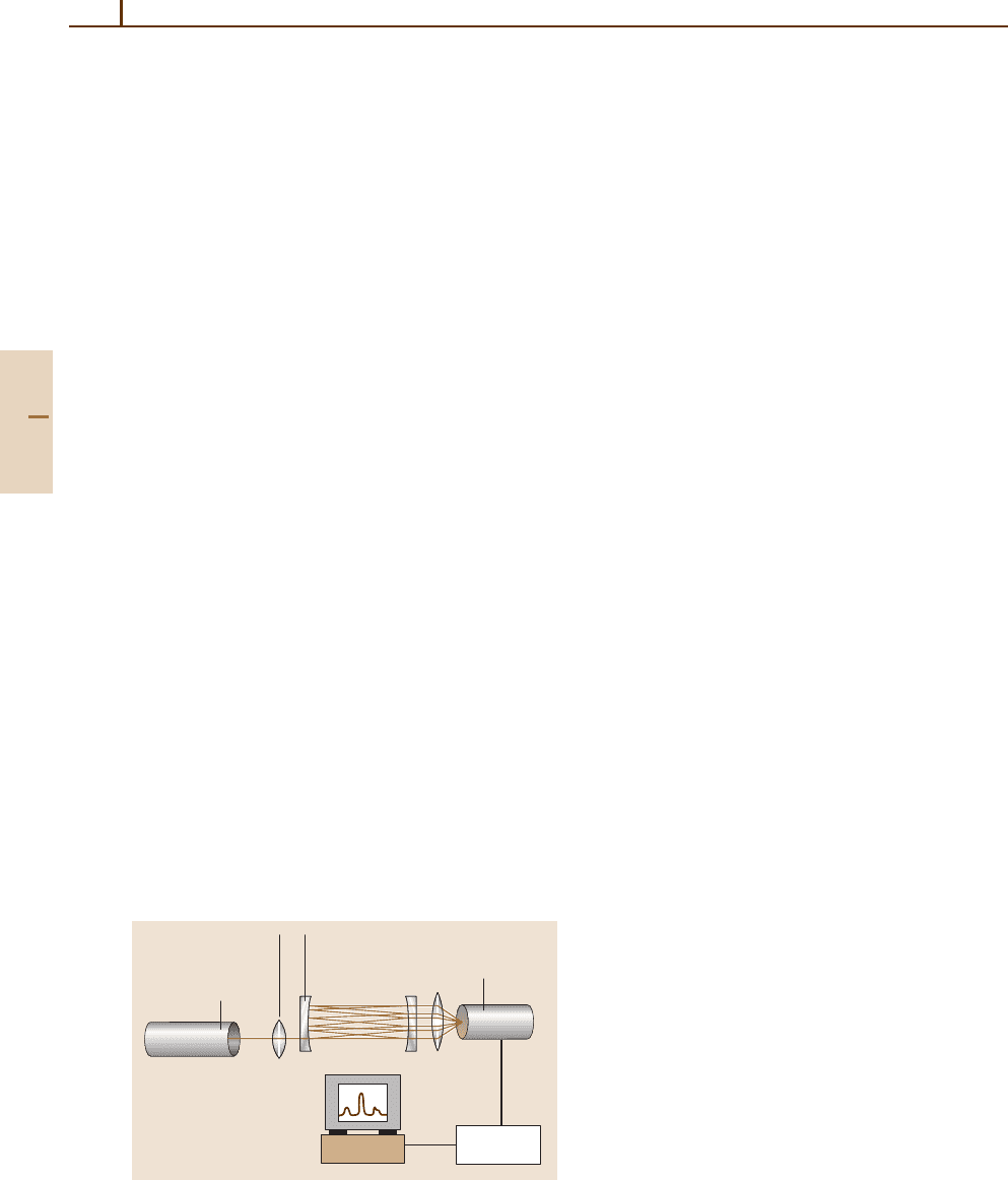
A third approach, called off-axis ICOS, resolves the
cavity transmission uniformity problem of CEAS,and
eliminates the need for modulation of ICOS.Inoff-
axis ICOS, shown in Fig. 43.3,theRDC is aligned so
as to generate a set of spatially separated reflections
High reflectivity mirrors:
Cavity/ Sample chamber
CW laser
Mode-matching
optics (optional)
Detector
PC
Integrator
Fig. 43.3 Typical off-axis ICOS setup
within the cavity that eventually satisfy the re-entrant
condition [43.19]. Furthermore, the mirrors are slightly
astigmatized, which results in Lissajous spot patterns
on the mirrors. The combination of this alignment and
slight astigmatism significantly reduces the RDC mode
degeneracy. As a result, the cavity mode spacing can
become smaller than the cavity mode width, the cavity
transmission appears to become largely frequency inde-
pendent, or “white”. Thus, the RDC provides path length
enhancement, without introducing intensity noise in the
transmitted spectrum. However, increasing the number
of spots on the mirrors usually requires larger mirrors
(e.g., 2 inches for off-axis ICOS versus 0.5 inches for
CRDS), which in turn results in a larger cavity (sample)
volume. In cases of low sample flow, sample chamber
filling times can limit the measurement time. Moreover,
the system is now dependent on the mechanical sta-
bility of the cavity and the laser to cavity alignment.
The best off-axis ICOS sensitivity achieved to date is
3×10
−11
cm
−1
Hz
−1/2
and is comparable to CW-CRDS.
43.3.2 Locked Cavity Enhanced
Transmission Spectroscopy (L-CETS)
An alternative approach (L-CETS) achieves higher sen-
sitivity by locking the laser frequency to a single cavity
resonance and then scanning the cavity over the absorp-
tion feature of interest [43.20]. In this case, the cavity
throughput becomes uniform across the entire spectral
scan, and the cavity transmission increases to the maxi-
mum theoretical value, leading to better signal to noise
at the detector than CETS approaches. Laser wavelength
jitter at high frequencies, which cannot be compensated
by the locking control loops, will lead to increased noise
in the spectral scans. In order to lock the laser and cav-
ity together robustly, the laser linewidth typically cannot
exceed the cavity mode resonance linewidth, so that for
a high finesse sample cavity, the laser choice can be
limited. Sensitivities of 10
−11
cm
−1
Hz
−1/2
have been
demonstrated using L-CETS.
The NICE-OHMS technique was developed to over-
come the dependence of L-CETS on laser wavelength
jitter [43.21]. NICE-OHMS combines the benefits of
frequency modulation (FM) spectroscopy with the path
length enhancements of a high finesse optical resonator.
The technique is called “noise immune”, because it does
not depend on the quality of the laser and cavity lock.
Effectively, it is immune to laser frequency noise al-
though residual amplitude modulation can reduce the
performance. NICE- OHMS sensitivity depends on the
transmitted laser power, the efficiency and bandwidth of
Part C 43.3