Drake G.W.F. (editor) Handbook of Atomic, Molecular, and Optical Physics
Подождите немного. Документ загружается.


1373
Charged-Parti
91. Charged-Particle–Matter Interactions
In the description of the interaction of fast
charged particles with matter, two aspects can be
distinguished: the effects on the particle, usually
energy losses and deflections, and the spatial
distribution of the energy lost by the particle in
the absorber.
This Chapter discusses concepts needed in
the operation of charged particle detectors
and in describing radiation effects (Chapt. 92).
Specifically, the radiation effects used for the
instantaneous observation (i. e., within fractions
of a millisecond) of the passage of a charged
particle are described. Delayed effects, such
as chemical reactions (e.g., biological effects,
chemical dosimeters, photographic emulsions),
metastable states, etc. are not discussed. It
is assumed that particle speeds have been
determined with, e.g., magnetic analyzers or by
measurement of the time of flight. A measurement
of particle ranges can also be used to determine the
initial speed. The description is restricted to fast
charged particles, defined by speeds v>6v
B
(v
B
is
the Bohr speed), or β = v/c > 0.04. Interactions
and cross sections at smaller speeds are discussed,
e.g., by Rudd et al.[91.1] and in [91.2].
The present Chapter primarily considers energy
loss straggling, rather than the stopping powers
discussed by Fano [91.3].
91.1 Experimental Aspects ...........................1374
91.1.1 Energy Loss Experiments
and Radiation Detectors.............1374
91.1.2 Inelastic Scattering Events..........1375
91.2 Theory of Cross Sections .......................1376
91.2.1 Rutherford Cross Section ............ 1376
91.2.2 Binary Encounter
Approximation..........................1376
91.2.3 Bethe Model of Cross Section ...... 1377
91.2.4 Fermi Virtual Photon Method ...... 1377
91.3 Moments of the Cross Section ...............1378
91.3.1 Total Collision Cross Section M
0
...1378
91.3.2 Stopping Power M
1
....................1379
91.3.3 Second Moment M
2
...................1380
91.4 Energy Loss Straggling .........................1381
91.4.1 Straggling Parameters................1381
91.4.2 Analytic Methods
for Calculating Energy Loss
Straggling Function ...................1382
91.4.3 Particle identification (PID)......... 1384
91.5 Multiple Scattering
and Nuclear Reactions .........................1384
91.6 Monte Carlo Calculations ......................1384
91.7 Detector Conversion Factors..................1385
References .................................................. 1385
It is important to understand that the mean energy-loss
is not a suitable concept to use in the description of
energy-loss spectra for thin absorbers. The most prob-
able energy-loss should be used instead. The methods
described here can be used to calculate reliable data
for detector applications. No attempt is made to present
a complete review. Anecdotal, qualitative examples of
various effects are described. The following definitions
are used:
1. The number of atoms or molecules per unit vol-
ume N = N
A
/A, with A the molecular weight
(in g/mole) of the absorber (with Z
2
electrons per
molecule), its density, and N
A
is Avogadro’s
number;
2. The relativistic factors β and γ for particles with rest
mass M
0
, speed v = βc and kinetic energy T :
β
2
=
T /M
0
c
2
2 +T /M
0
c
2
1 +T /M
0
c
2
2
,
γ = M/M
0
= 1 +T /M
0
c
2
,
γ
2
= 1/
1 −β
2
,
β
2
γ
2
= γ
2
−1 ;
Part G 91
1374 Part G Applications
3. The coefficient of the Rutherford equation:
k
R
=
2πZ
2
1
e
4
m
e
c
2
= 2πr
2
0
m
e
c
2
Z
2
1
= 2.549 55 × 10
−19
Z
2
1
eV c m
2
, (91.1)
where m
e
is the rest mass of an electron, −e its
charge, Z
1
e the charge of the incident particle, and
r
0
= α
2
a
0
is the classical electron radius; and
4. The maximum energy loss of a heavy particle to an
electron: E
max
∼ 2m
e
c
2
β
2
γ
2
[91.4].
91.1 Experimental Aspects
91.1.1 Energy Loss Experiments
and Radiation Detectors
After passing through a thickness x of material, an
initially monoenergetic beam of particles acquires a dis-
tribution of energies described by a probability density
function
F(∆) =
dN (∆)
d∆
,
(91.2)
where ∆ is the energy loss per particle, and dN (∆)
is the number of particles in the range ∆ to ∆ + d∆.
The straggling function F(∆) represents the spectrum
of energy losses ∆, such that
F(∆) d∆ = N , the total
number of particles observed. It can be characterized by
the quantities
1. the most probable energy loss ∆
mp
,
2. the full width at half maximum Γ ,
3. the moments [91.8]
µ
ν
=
1
N
F(∆)∆
ν
d∆, (91.3)
and the central moments
C
ν
=
1
N
F(∆)(∆ −µ
1
)
ν
d∆. (91.4)
Then µ
1
=∆ is the mean energy loss, C
2
= σ
2
is
the variance and γ
1
= C
3
/C
3/2
2
is the skewness. The
fluence spectrum φ(T ) is the complementary function
describing the distribution of residual energies T of the
particles.
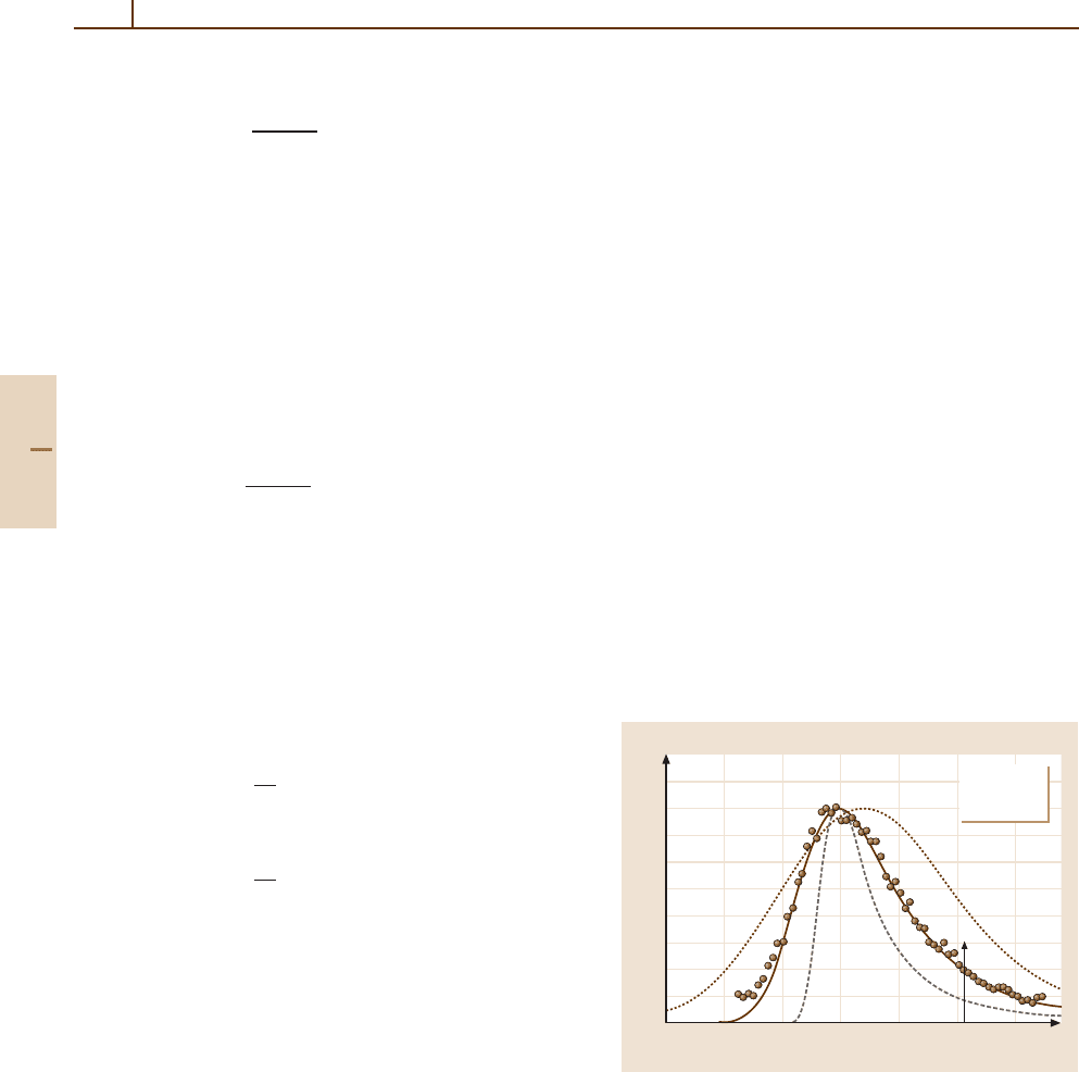
As an example, Fig. 91.1 shows F(∆) d∆ for
1.27 GeV protons passing through a 32 µm thick silicon
wafer [91.5]. The measured quantity is the ionization J
resulting from the creation of electron–hole pairs in the
silicon, so that ∆ = JW is the energy deposited, where
W is the energy required to create an electron–hole pair.
For ∆<15 keV, the energy deposited differs little from
the energy lost by the protons. For larger ∆, some of the
secondary electrons may escape from the silicon, mak-
ing the apparent energy deposited less than the energy
lost [91.9]. The spectrum has a long tail extending up to
a maximum energy loss of 4.6 MeV. This accounts for
the large value of ∆=12.8 keV, and the even larger
value C
1/2
2
= 43 keV for the standard deviation, relative
to ∆
mp
= 7.4keVandΓ = 5.2keV.
In losing energy, the beam particles also suffer an-
gular deflections, but for heavy particles, the deflections
are usually small. For electrons, angular deflections are
quite important, and are discussed in Chapts. 47, 64,
and 65. Nuclear reactions cause large effects but are
quite infrequent. Further examples of straggling spec-
tra are given in [91.5, 10–12] for thin, extremely thin,
moderately thick, and thick absorbers respectively.
Only for thick absorbers, the stopping power
S(T ) =−dT /dx (i. e., the mean energy lost per unit
thickness) provides a convenient measure of the energy
loss process. For a beam with incident energy T
0
and
250
200
150
100
50
0
∆(keV)
0 5 10 15
dN(∆) = F(∆)d∆
<∆>
1.27 GeV p
32 µm Si
N = 6000
Fig. 91.1 Energy loss straggling functions F(∆) d∆ for
1.27 GeV protons traversing a 32 µm silicon detector, with
d∆ = 0.21 keV. The experimental data are shown by cir-
cles. Three calculated functions normalized to the same
peak height are shown for comparison [91.5]. The solid line
was calculated with the Bethe cross section Fig. 91.3 with
∆
mp
=7.4keV,Γ =5.2keV,and∆=12.8keV.Thebro-
ken line is the Landau function [91.6]andthedotted line is
the Blunck–Leisegang modification [91.7]
Part G 91.1
Charged-Particle–Matter Interactions 91.1 Experimental Aspects 1375
∆ < 0.1T
0
, S(T ) is often approximated by
S(T
0
−∆/2) ∆/x , (91.5)
provided that x a
0
(Sect. 91.4). The stopping power
S(T ) depends on the absorber properties, especially
the electron density NZ
2
. The radiation dose D(x) at
a distance x into the material is given by
D(x) =
φ(T , x)S(T )dT ,
(91.6)
where φ(T , x) is the fluence spectrum. D(x) is used in
radiation dosimetry and protection [91.15, 16].
S(T ) ceases to be useful for very thin absorbers,
such as microscopic biological specimens, micro- or
nano-devices, or thin ionization chambers. Instead ∆
mp
and Γ should be used. No simple equations can provide
∆
mp
and Γ . They must be found from calculated or
experimental F(∆). Calculations of F(∆) are described
in 91.4.2 and 91.6.
A detailed theoretical description of the energy de-
position process requires cross sections for the various
scattering events in the target, the most important being
collisions with electrons. The Rutherford cross section
for the collision of a particle with a free electron is only
useful for ∆
30 U
Z
,whereU
Z
is the binding energy
of a target electron (∼ 500 eV for outer shell electrons).
Various modifications to the Rutherford cross section
for smaller ∆ are discussed in Sect. 91.2.
91.1.2 Inelastic Scattering Events
If a beam of N monoenergetic particles with speed v
passes through an absorber of infinitesimal thickness dx,
the average number of particles experiencing a collision
with energy loss between E and E + dE is given by
dN (E) = N Nσ(E) dE dx ,
(91.7)
where σ(E) is the collision cross section per molecule
differential in E; it depends on β. Using this equation,
σ(E) can be obtained from measurements [91.17, 18]
with extremely thin absorbers where particles on the
average suffer less than one collision. If particles pass
through a thicker absorber, they make several collisions
with energy losses E
i
; and the total energy loss is ∆ =
E
i
(Sect. 91.4.2).
Large differences exist between a gas and a solid
of the same composition due to changes in the va-
lence shell electrons. In isolated atoms [91.14], the
smallest energy losses are to discrete excited electronic
states. Ionizations occur for energy losses exceed-
ing the binding energies U
l
for each atomic shell l
and the released electrons are given a kinetic energy
δ = E −U
l
. For ionization, energy losses are contin-
uous (Fig. 91.2). If atoms are brought closer together
to form a liquid or a solid, their valence electrons
come under the influence of the cores of surround-
ing atoms. A core is defined to consist of the nucleus
and all the electrons inside the valence shell. For C,
O, or H
2
O, the core consists of two electrons in the
K-shell, for Al or Si it contains two electrons in the
K-shell and eight electrons in the L-shell. For metals,
the valence electrons form a conduction band where
they are nearly free. If a charged particle moves through
the solid, the transfer of very small energies to the
electron by Rutherford scattering is not observed. In-
stead, many thousands of them are excited at a time.
For metals, this process is called plasmon excitation,
for insulators, collective excitation (Fig. 91.2). For most
substances, the plasmon excitation energy E
p
is much
larger than the energy of the lowest excited state of
the atom E
1
. For example, for Be, E
1
= 3.6 eV [91.13],
while E
p
= 19 eV [91.17]. Similarly, for silicon,
E
1
= 3.6 eV [91.13]andE
p
= 16.7 eV [91.5].
For molecules, measurements of electron energy
losses [91.18] provide information about the difference
in the structure of σ(E) between gas and solid. For ex-
ample, for benzene (C
6
H
6
) the vapor shows distinct
structures for excitations to several discrete states, and
10
0
10
–1
10
–2
10
–3
10
–4
2 5 10 20 50 100 200
f(E O)(eV
–1
)
E(eV)
solid, I = 174 eV
gas,
I = 131 eV
ln I = f( ) ln d
⑀⑀⑀
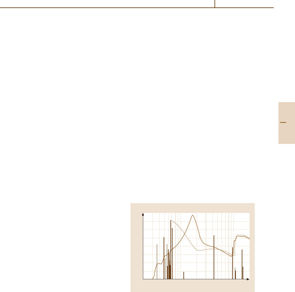
Fig. 91.2 Comparison of the dipole oscillator strength spec-
tra for atomic and solid silicon. Discrete atomic excitations
are shown by vertical lines, continuum excitations by
the dotted line. Data for the atom are based on calcula-
tions [91.13]. Data for the solid are from [91.5]. The broad
peak at ≈ 17 eV represents the plasmon excitations. Uncer-
tainties may exceed 10%. The discrete atomic excitations
disappear in the solid. The photoionization cross section is
σ(E) = 109.8 f(E) Mb [91.14]
Part G 91.1
1376 Part G Applications
a broad peak at about 16 eV which appears to be equiva-
lent to a collective excitation. For the solid, the structures
are broadened, and the major peak for the collective ex-
citations shifts to 21 eV. Data for water can be found
in [91.19].
For energy losses well above E
p
, σ(E) decreases
smoothly until the ionization energy of the next electron
shell is reached, as shown in Fig. 91.2. In a molecular
substance such as CaCO
3
, several broad peaks appear
between 7 and 40 eV, followed by narrow peaks at 280 eV
(carbon K-shell), 345 eV (Ca L-shells), 530 eV (oxygen
K-shell) and 4 keV (Ca K-shell) [91.17].
While there are large changes in the structure of
the excitation of the valence electrons as the atoms
are coalesced into a solid (Fig. 91.2), changes are less
important for the inner shells because the binding en-
ergies of these shells are much larger than chemical
energies. As an example, for an amorphous thin car-
bon film, the K-edge is at 284 eV [91.17], and K-shell
excitation shows essentially just one peak at ≈ 296 eV.
For the three biologically important molecules adenine,
uracil and thymine, several peaks appear [91.20], all
located between 284 and 300 eV. Thus there is at most
a small change in the energy of the K-shell excitation, but
the number of peaks as well as their locations changes
considerably. For Al above the K-edge (1.56 keV),
a structure with several peaks appears [91.21], with
separations of about 40 eV. This structure, called ex-
tended X-ray absorption fine structure (EXAFS) [91.22],
is caused by the presence of nearby atomic cores
which backscatter the photoelectrons and thus change
their wave functions. The discrete excitations of the
atom below the K-edge disappear completely. Thus
solid state and chemical effects are very important
for valence shell electrons, and less so for inner-shell
electrons.
91.2 Theory of Cross Sections
The cross section for the collision of two free
charged particles is given by the Rutherford ex-
pression. If charged particles collide with electrons
bound in atoms, molecules or solids, the cross sec-
tion can be written as a modified Rutherford cross
section. A plausible way of describing these interac-
tions is to consider the emission of virtual photons
by the fast particle, which then are absorbed by
the material in the Fermi virtual photon method
(FVP) [91.23]. The collision cross section then is pro-
portional to the photo absorption cross section of the
molecules. Bohr [91.24] described this as a “resonance”
effect.
A variety of models has been used to obtain theoret-
ical σ(E) for bound electrons. Here, three of them will
be described and compared with each other. Examples
are shown in Fig. 91.3. Few analytic functions and meth-
ods are available to calculate cross sections (Chapt. 47).
Usually, numerical calculations must be made to obtain
reliable data for real absorbers.
91.2.1 Rutherford Cross Section
The cross section for close collisions of fast charged
particles with loosely bound electrons is well approxi-
mated by the cross section for the collision of a charged
particle with a free electron at rest. The nonrelativistic
Rutherford cross section σ
R
(E) foranenergylossE in
the collision of a charged particle with speed v in the
laboratory frame is given by [91.25–28]
σ
R
(E) =
2πZ
2
1
e
4
mv
2
1
E
2
=
k
R
β
2
1
E
2
. (91.8)
Since the secondary electron receives all the energy E
lost by the incident particle, the momentum transfer is
q =
√
2mE. The cross section σ
R
(E) does not depend on
particle mass M. The leading relativistic correction (For
γ>M/m, further terms must be included [91.29–31])
is
σ
R
(E) = σ
R
(E)
1 −β
2
E
E
max
x
. (91.9)
91.2.2 Binary Encounter Approximation
A simple correction to σ
R
(E) can be achieved by tak-
ing into account the velocity of the bound electrons.
With binding energy U
b
, average kinetic energy T
e
,and
average speed u of the electrons, the expression is
σ
L
(E) = σ
R
(E)
1 +
4
3
T
e
E
, E > U
b
, (91.10)
which is valid for v u. The total cross section
for a molecule includes contributions from each elec-
tron shell. Variants of this approach are described
in [91.32, 33]. Figure 91.3 shows an example.
Part G 91.2
Charged-Particle–Matter Interactions 91.2 Theory of Cross Sections 1377
10.0
10 30 100 300 1000 3000 10000
30000
100000
4.0
2.0
1.0
0.4
0.2
0.1
σ( )/ ( )
⑀⑀
(eV)
⑀
Fig. 91.3 Inelastic cross sections σ(E) for single colli-
sions in solid silicon, for incident protons with an energy
T = 100 MeV, calculated using different theories. The hor-
izontal line at 1.0 represents the Rutherford cross section
from (91.8). The other curves are Bethe theory (solid line);
FVP approximation (dashed line); binary encounter ap-
proximation from (91.10) [91.32](dotted line). The curves
extend to E
max
= 230 keV
91.2.3 Bethe Model of Cross Section
The Bethe model [91.34] derives from the first Born ap-
proximation for inelastic scattering, which becomes es-
sentially exact at high energies. In terms of the inelastic
form factor |F (E, K)|
2
, the energy loss cross section is
dσ(E, Q) = σ
R
(Q)|F (E, K)|
2
dQ , (91.11)
where Q = q
2
/2m
e
,and K is the momentum trans-
fer vector. The generalized oscillator strength (GOS)is
defined by
f(E, K) = E|F (E, K)|
2
/Q , (91.12)
such that f(E, K) reduces to the optical dipole oscillator
strength f(E, 0) ≡ f(E) in the limit K → 0. Then
dσ(E, Q) = σ
R
(E)Ef(E, K) dlnQ . (91.13)
For hydrogenic atoms, f(E, K) is well known
[91.34–38], and a model spectrum is shown in Fig. 10
of [91.27, 28]. For more complicated atoms, many-
electron effects introduce small corrections, as shown
in Fig. 91.4 for Si using a Hartree–Fock approxima-
tion. Adding the contributions from all shells yields
the Bethe result in Fig. 91.3 [91.5]. Similar results are
given in [91.39] for Al. For the outermost electrons in
metals, the electron gas model can be used to generate
cross sections [91.40–42]. For semiconductors and insu-
lators a model has been derived using the tight binding
approximation for the ground state wave function and
orthogonalized plane waves for excited states [91.41].
The dipole oscillator strength is derived from the data
for optical absorption coefficients; for solids [91.43]and
gases [91.44–46] see Chapt. 61.
91.2.4 Fermi Virtual Photon Method
In the Fermi virtual photon (FVP) method, f(E, K) is
approximated by f(E, 0) for Q < E, with a delta func-
tion at Q = E [91.23, 47–50](Fig.91.4). Then σ(E) is
given by [91.48]
σ(E) = σ
R
(E)
Ef(E, 0) ln
2mv
2
E
+
E
0
f(E
, 0) dE
,
(91.14)
andsoonly f(E) need be known, or equivalently
Im(−1/),where is the complex dielectric constant
of the absorber. Data can be extracted from a variety of
optical measurements [91.43,44, 51], and from electron
0.12
0.10
0.08
0.06
0.04
0.02
0.00
K(a.u.)
024 68101214
f(E, K)(Ry
–1
)
E = 48 Ry
Fig. 91.4 Generalized oscillator strength (GOS) f(E, K)
(solid line) for longitudinal excitations of the 2p-shell of Si
atoms (with a binding energy U
L
= 8 Ry), calculated with
the Hartree–Fock–Slater potential. The energy transfer is
E = 650 eV. The hydrogenic approximation is given by the
broken line; f(E, K) peaks at (Ka
0
)
2
≈ E −U
L
.Inthe
FVP model, (91.14), the GOS is replaced by a δ-function at
Ka
0
= E
1/2
and by f(E, 0) for 0 < Ka
0
< E
1/2
(straight
lines)
Part G 91.2
1378 Part G Applications
energy loss measurements [91.52]. A cross section cal-
culated with this model is given in Fig. 91.3.Theσ(E)
differ by as much as 50% from the Bethe result, but the
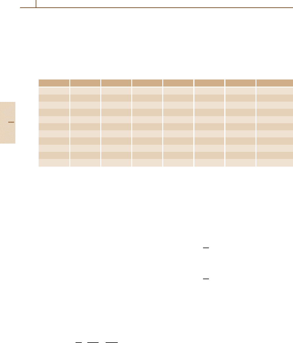
Table 91.1 The coefficient τ(β) = M
0
β
2
/(NZk
R
) for pions with M
π
= 139.567 MeV/c
2
, calculated in the FVP approxi-
mation. For comparison, the Si (GOS) results were calculated from the complete F(E, K) generalized oscillator strengths.
The estimated accuracies are ≈ 1% for Si (GOS)and∼ 30% for the others. The values are the same for all heavy par-
ticles with the same β; they differ slightly for electrons. For Si
=2.329 g/cm
3
, NZk
R
= 17.82 eV/µm, for the gases
(at STP), NZk
R
= 6.3828 Z eV /cm. Units of τ(β) are eV
−1
T (MeV) β Si(GOS) Si He Ar Ethane Butane
UT 1. 0.11907 0.1208 0.1333 0.1937 0.1081 0.2961 0.2855
3. 0.20406 0.1408 0.1528 0.2229 0.1242 0.3379 0.3259
10. 0.35950 0.1612 0.1738 0.2538 0.1412 0.3821 0.3686
30. 0.56791 0.1792 0.1917 0.2802 0.1557 0.4198 0.4050
100. 0.81276 0.1957 0.2082 0.3093 0.1717 0.4614 0.4451
300. 0.94825 0.2061 0.2186 0.3441 0.1908 0.5111 0.4931
1000. 0.99247 0.2127 0.2252 0.3958 0.2189 0.5843 0.5637
3000. 0.99901 0.2150 0.2275 0.4499 0.2468 0.6580 0.6333
10000. 0.99991 0.2155 0.2280 0.5057 0.2671 0.7034 0.6646
30000. 0.99999 0.2156 0.2281 0.5332 0.2737 0.7111 0.6697
100000. 1.00000 0.2156 0.2281 0.5407 0.2765 0.7128 0.6709
moments differ by at most 10% (Table 91.1). It is ev-
idently a better approximation than that given by the
binary encounter approximation of (91.10).
91.3 Moments of the Cross Section
Various moments of σ(E) are defined by [91.5, 53]
M
ν
≡ N
E
ν
σ(E) dE . (91.15)
where the range of integration covers all non vanish-
ing σ(E), including a summation over discrete excited
states. Then M
0
= Nσ
tot
= 1/λ
mfp
,whereσ
tot
is the to-
tal collision cross section and λ
mfp
the mean free path
between collisions, and M
1
= S, the stopping power.
M
2
and M
3
give the width and skewness of F(∆).
Higher moments are not very useful [91.53] except
for special applications [91.54–56]. For incident elec-
trons, a further averaging of energy loss over different
paths must be performed because of multiple angular
scattering.
91.3.1 Total Collision Cross Section M
0
A simple result for M
0
is obtained with the Rutherford
cross section
R
M
0
= NZ
2
σ
R
(E) dE
= NZ
2
k
R
β
2
1
E
min
−
1
E
max
.
(91.16)
Clearly,
R
M
0
is very sensitive to the choice of E
min
,
and there is no simple prescription for choosing it, as
is evident from Fig. 91.3. The same applies to the bi-
nary encounter approximation [91.32]. From the Bethe
model, a good relativistic approximation to M
0
is given
by [91.27, 28, 57]
M
0
= NZ
2
k
R
β
2
g
0
×
lnβ
2
γ
2
−β
2
+h
0
+11.227
= NZ
2
k
R
β
2
τ(β) . (91.17)
Val ue s for g
0
and h
0
may be found in [91.57]. For
Si, He, Ar, ethane, and butane, values of τ
β
, cal-
culated by numerical integration of σ(E) obtained
with the FVP method, are given in Table 91.1.
For Si, comparison values calculated with the Bethe
model are also given. The quantity τ(β) is more
suitable for interpolation than M
0
. An extensive de-
scription of cross sections are given for liquid water
in [91.58].
Part G 91.3
Charged-Particle–Matter Interactions 91.3 Moments of the Cross Section 1379
91.3.2 Stopping Power M
1
The stopping power is usually written in the form
M
1
= S = NZ
2
k
R
β
2
2B , (91.18)
where B is called the stopping number. M
1
calculated
with the Rutherford cross section is
R
M
1
= NZ
2
E
max
E
1
Eσ
R
(E) dE = NZ
2
k
R
β
2
ln
E
max
E
1
.
(91.19)
To obtain realistic values, it is evident from Fig. 91.3 that
asmallvaluemustbechosenforE
1
to compensate for
the peaks in σ(E). Note that for most applications in high
energy physics (e.g. Time Projection Chambers [91.59,
60]) M
1
is not useful [91.4].
The Bethe Model
In the Bethe model of stopping powers, dσ(E, K)
from (91.13) must be integrated over both E and
Q =
2
K
2
/2m [91.37,38]. Since f(E, K) is nearly con-
stant near K = 0 [91.61](Fig.91.4), the integral may be
broken into four parts according to
S =
N k
R
β
2
dE
Q
1
Q
m
f(E, 0)
dQ
Q
+
∞
Q
1
f(E, K)
dQ
Q
+
Q
1
0
[ f(E, K) − f(E, 0)]
dQ
Q
−
Q
m
0
[ f(E, K) − f(E, 0)]
dQ
Q
,
(91.20)
where Q
m
≈ E
2
/2mv
2
[91.27, 28], and Q
1
is cho-
sensuchthat f(E, K) differs little from f(E, 0) in
the interval 0 ≤ K ≤
√
2mQ
1
/ [91.36, 62]. Collisions
with Q < Q
1
are “distant” and those with Q > Q
1
are
“close”. The integrals simplify by interchanging the or-
der of integration in the second and third terms, and by
using the sum rule [91.27, 28, 34]
∞
0
f(E, K) dE = Z
2
, (91.21)
for all K. The last term of (91.20) is then small and the
second last vanishes exactly. The remaining two terms
give
S =
NZ
2
k
R
β
2
ln
2mv
2
Q
1
2
+ln
Q
max
Q
1
,
(91.22)
where is the logarithmic mean excitation energy de-
fined by
Z
2
ln =
f(E) ln E dE , (91.23)
and Q
max
= 2m
e
c
2
β
2
γ
2
is the maximum energy loss
for electrons, Q
max
=
1
4
m
e
c
2
β
2
γ
2
[91.3]
. Including
relativistic and other correction terms, the final result
for M
1
m
e
is
S =
N Z
2
k
R
β
2
2
B
0
−
C(β)
Z
2
+ Z
1
L
1
(β) +Z
2
1
L
2
(β)
+
1
2
[G(M
1
,β)−δ(β)]
, (91.24)
where
B
0
= ln
2mc
2
β
2
γ
2
−β
2
(91.25)
is the uncorrected stopping number. In the limit β → 0,
2B
0
reduces to the terms in brackets in (91.22). The
other correction terms are as follows [91.31].
The Shell Correction. C(β) accounts for the last term in
(91.20), together with modifications of dσ(E, Q) near
Q = E
max
[91.3]. It can be estimated on a shell-by-
shell basis [91.63–66] using nonrelativistic hydrogenic
calculations for the K- and L-shells [91.35, 37, 38],
and rescaling methods for the outer shells which have
not been calculated directly [91.63, 64, 67]. The ef-
fects are important for small β, but simple formulas
are not known. A calculation for Al and Si based on
a model more realistic than the hydrogenic one is given
in [91.68].
The Barkas Term. L
1
(β) arises from polarization of the
target electrons by the incident particle [91.69,70]. Var-
ious approximating functions and fits to experimental
data are described in [91.71].
The Bloch Term. L
2
(β) arises from corrections to the
approximation that for close collisions, the electrons
can be represented by plane waves [91.72]. Confine-
ment of the electrons to the interior of a cylinder of
atomic dimensions introduces transverse momentum
components, resulting in the widely used correction
Z
2
1
L
2
(β) =−q
2
∞
j=1
1/
j
j
2
+y
2
(91.26)
Part G 91.3
1380 Part G Applications
with y = Z
1
α/β.Fory =0, the sum is ζ(3) 1.202 057.
A new approach can be found in [91.73, 74]. The need
for the L
1
and L
2
terms was established experimen-
tally in [91.75], and discussed in a more general context
in [91.76].
The Mott Term. G(M
1
,β) is a kinematic recoil correc-
tion which becomes important for relativistic projectiles.
In the limit of a point-like spinless nucleus, the correc-
tion is
G(M
1
,β)=−ln(1 +2t) −tβ
2
/γ
2
, (91.27)
where t = mγ/M
1
[91.29]. The correction is negligible
for γ<100 and M
1
> m
p
.
The Density Correction. δ(β) arises from the dielectric
response of a solid absorber as a whole to the electric
field of the projectile, and the work done by the inter-
action [91.3, 29]. Sternheimer’s algorithm [91.77, 78]is
usually used, as summarized in [91.29].
The remaining parameter to be discussed in (91.24)
is . If the oscillator strength distribution f(E) is known,
then can be calculated directly from (91.23). Results
for many gases are given in [91.45]. The values give good
agreement with experimental stopping powers [91.79].
For solids, the definition [91.3]
ln =
2
π( ω
p
)
2
∞
0
E Im
−1
(E)
ln E dE
(91.28)
may be used, where ω
p
is the plasma energy for all
the electrons, defined by (
ω
p
)
2
= 830.4 Z/A with
ω
p
in eV. For metals, this is substantially larger than
the plasmon energy associated with the conduction
electrons. Only for Al [91.80] and for water [91.81]
have sufficiently good measurements of Im[−1/(E)]
been available to permit the use of this method. For
other materials, can be deduced from measurements
of S, provided that the other corrections in (91.24)are
known sufficiently well. A list of values for all elem-
ents and many compounds is given in [91.66]. See
also [91.25, 63–65, 79, 82–87].
For rough estimates of , the approximation [91.88]
≈
11.7 +11.2/Z
2
eV , Z
2
≤ 13
9.5 ±1eV , Z
2
> 13
(91.29)
is useful, together with the Bragg rule
n
e
ln =
i
n
i
ln
i
(91.30)
for compounds and composite materials, where n
i
is the
electron density associated with element i.However,
chemical shifts may be as large as 10% [91.89].
The Fermi Virtual Photon Method
From (91.14), the nonrelativistic FVP approximation to
the stopping number B(β) is
B(β) =
1
2
ln
2m
e
v
2
+
1
2Z
2
E
max
E
min
dE
E
E
0
f(E
) dE
. (91.31)
Although the integrals must now be calculated numer-
ically, the full f(E, K) is not required, and in the case
of silicon, the results are in close agreement with the
corresponding Bethe model.
Stopping Power at Small Speeds
For small speeds, the various correction terms in the
stopping number B,(91.24), become large compared
with B
0
[91.63, 64, 68]. In particular, for 2mv
2
=, B
0
becomes zero. For example, for α-particles in U (=
840 eV), B
0
= 0atT = 1.5MeV, and B then consists
only of correction terms. For smaller energies, empirical
approaches are used to describe S. Many of the tables
referenced above give such data.
Mean Energy Loss per Collision
The quantity E=M
1
/M
0
is the mean energy
loss per collision. For substances with Z < 20,
E∼50–100 eV. It changes at most by a factor of 1.5
for βγ > 0.1. In order to choose a suitable method for
calculating straggling functions, it is useful to estimate
the number of collisions in a thickness x of absorber.
For less than 2000 collisions, the convolution method of
Sect. 91.4.2 should be used (Fig. 15 in [91.5]).
91.3.3 Second Moment M
2
The relativistic result calculated with the Rutherford
cross section is
R
M
2
= NZ
2
k
R
β
2
1 −β
2
/2
E
max
(91.32)
= 2NZ
2
k
R
mc
2
1 −β
2
/2
1 −β
2
= 0.156 915
Z
2
1
Z
2
A
1 −β
2
/2
1 −β
2
MeV
2
cm
2
/g .
For small β,
R
M
2
is practically independent of β.
A better approximation can be achieved with the binary
Part G 91.3
Charged-Particle–Matter Interactions 91.4 Energy Loss Straggling 1381
encounter method:
b
M
2
= NZ
2
k
R
β
2
E
max
1 −
β
2
2
+
l
4Z
l
U
l
3Z
2
E
max
ln
E
max
l
E
min
−β
2
,
(91.33)
where the summation extends over atomic shells l.For
l
E
min
the ionization energy J
l
for shell l can be used,
while U
l
represents the kinetic energy of the electrons
in shell l. This approximation is only useful for rela-
tively large x [91.5]. By using sum rules, Fano [91.3,
(72)] achieved a better approximation, which corres-
ponds to the Bethe approximation for the stopping power
[91.5, 90]. Hydrogenic values of M
n
are calculated
in [91.53].
91.4 Energy Loss Straggling
91.4.1 Straggling Parameters
Parameters for Thick Absorbers
Straggling is due to the stochastic nature of the en-
ergy losses of the charged particles. Because the single
collision spectrum is highly skewed (the most proba-
ble energy loss is ≈ 20 eV, the mean value ≈ 100 eV),
straggling functions will also be skewed. Four param-
eters are useful in a preliminary study of straggling
problems [91.47]. The parameter
ξ = NZ
2
k
R
β
2
x = 153.537
Z
2
1
β
2
Z
2
A
x keV cm
2
(91.34)
gives the energy loss [calculated with σ
R
(E)]which,
on the average, is exceeded once for each particle in
its passage through an absorber of thickness x,i.e.,for
ξ E
max
,
xNZ
2
E
max
ξ
σ
R
(E) dE = 1 . (91.35)
The parameter κ = ξ/E
max
is related to the skewness
of the straggling function: γ
2
1
= 1/4κ. The mean energy
loss is
∆=xM
1
= 2ξ2B = 2κE
max
B , (91.36)
and the standard deviation of F(∆) is
ω
2
= xM
2
∼ xNZ
2
k
R
β
2
E
max
= ξE
max
= κE
2
max
.
(91.37)
For thick absorbers, the straggling function becomes
approximately Gaussian [91.5, 24]. The requirement for
this to occur is γ
1
→ 0, thus κ →∞,also∆→∞,
and x →∞.
Parameters for Thin Absorbers
The parameters described above are not suitable for de-
scribing F(∆) for very thin absorbers. Instead, ∆
mp
and
Γ are used. Values for pions traversing Ar are given as
a function of thickness x in Tables 91.2, 91.3.However,
before comparing with experimental data, values of ∆
must be converted into ionization values, and the detec-
tor and amplifier noise must be added [91.5] (Sect. 91.7).
Landau [91.6] gave an expression for the most proba-
ble energy loss as a function of particle speed. It was
modified in [91.5]to
∆
L
= ξ
ln
2mc
2
β
2
γ
2
I
+ln
ξ
I
+0.200 −β
2
−δ
.
(91.38)
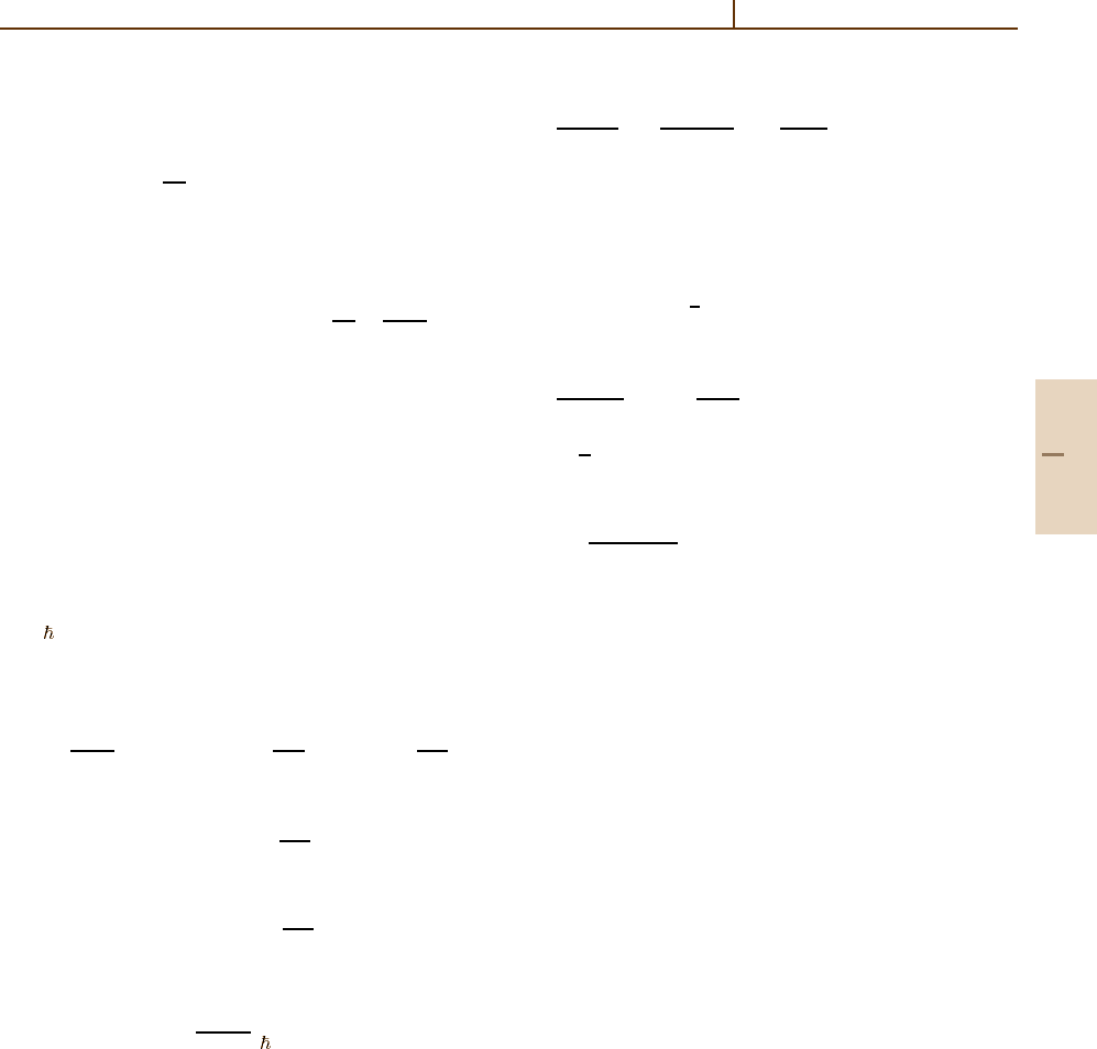
Table 91.2 Calculated most probable energy loss ∆
mp
of pions with Z
1
=±1 and kinetic energy T passing
through a distance x of argon gas
at 760 Torr, 293 K,
= 1.66 g/dm
3
. For heavy ions (α,C
+
), the values scale
as Z
1.3
1
(for a better approximation, see Table V in [91.5]).
Units of ∆
mp
are keV. The quotient ∆
mp
/x increases with x
x(cm)
T (MeV) 0.5 1 2 4 8
1 29.373 63.341 130.662 265.062 533.811
3 9.820 21.598 47.000 101.329 216.013
10 3.104 6.842 14.950 32.558 69.966
30 1.153 2.687 5.927 12.883 28.023
100 0.376 1.274 2.928 6.412 13.884
300 0.288 0.973 2.313 5.099 10.993
1×10
3
0.303 1.042 2.445 5.356 11.494
3×10
3
0.344 1.217 2.783 6.044 12.926
1×10
4
0.384 1.390 3.145 6.784 14.495
3×10
4
0.653 1.515 3.405 7.322 15.663
1×10
5
0.667 1.605 3.595 7.725 16.575
Part G 91.4
1382 Part G Applications
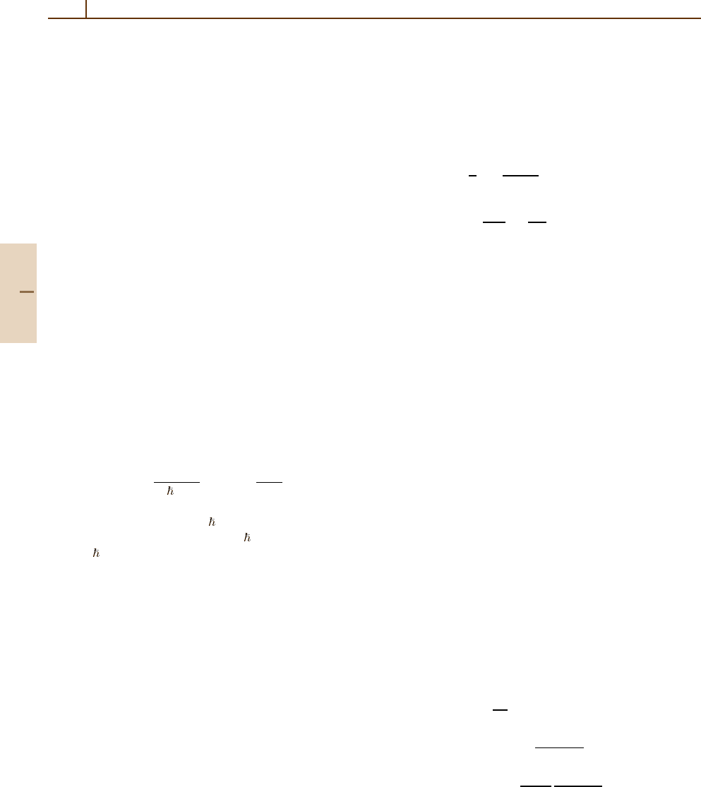
Table 91.3 Calculated values of Γ (fwhm) of the straggling
function F(∆) (see Table 91.2). As a rough approximation,
Γ ∼ x
0.8
(Table VI in [91.5])
x(cm)
T (MeV) 0.5 1 2 4 8
1 16.014 24.961 35.503 51.327 69.120
3 6.283 12.012 22.928 43.393 68.589
10 2.507 4.563 8.659 16.153 30.026
30 1.360 2.279 3.922 7.441 13.881
100 0.781 1.434 2.350 4.178 7.705
300 0.574 1.239 2.030 3.410 6.232
1×10
3
0.621 1.286 2.085 3.397 6.340
3×10
3
0.752 1.391 2.244 3.687 6.844
1×10
4
0.905 1.510 2.432 3.999 7.502
3×10
4
0.983 1.615 2.548 4.314 7.956
1×10
5
1.040 1.701 2.689 4.666 8.399
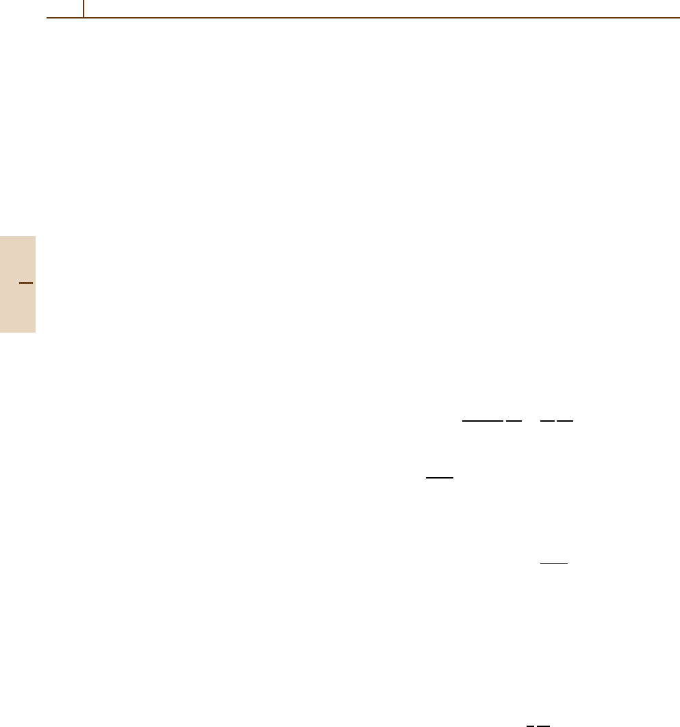
1.8
1.6
1.4
1.2
1.0
1 5 10 50 100 500 1000
scaled ∆
p
/x
80 cm
30 cm
4 cm
2 cm
1 cm
βγ
BBx = 1, 2, 4, 30, 80 cm Ar
Fig. 91.5 The dependence of most probable energy-loss
values ∆
mp
(βγ ; x)/x > for segments of length x. Solid
line BB: the Bethe–Bloch function dE/dx(βγ) [91.4].
Other lines are for the segment lengths x marked at right.
The functions are scaled with a factor g(x) such that they
concide at minimum ionization
More accurate functions ∆
mp
are obtained with the
collision spectra of Fig. 91.3, and are called Bich-
sel functions [91.59]. For sufficiently large ξ, ∆
mp
,
and ∆
L
agree within a few %. Examples are shown in
Fig. 91.5, and for comparison the Bethe-Bloch function
dE/ dx [91.4]isgiven.
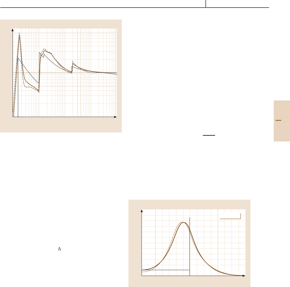
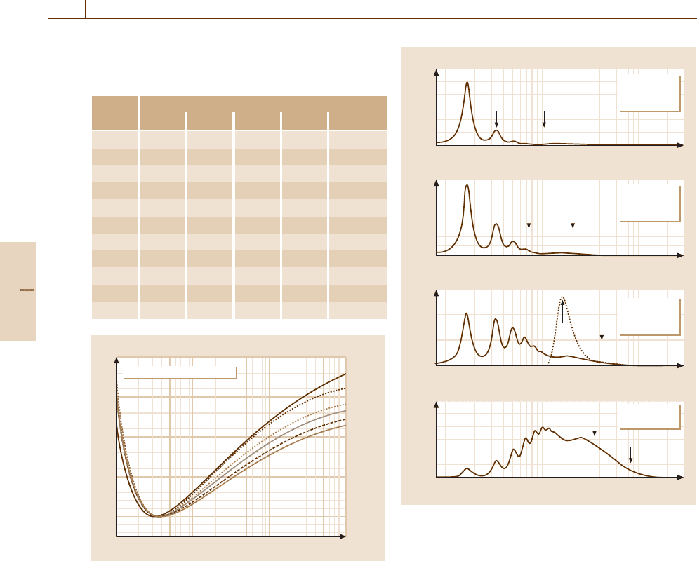
Parameters for Extremely Thin Absorbers
If the number n
c
of collisions in the absorber is less than
about 16, F(∆) still shows the details of σ(E) (Fig. 91.6).
0.04
0.02
0
10 100 1000
0.03
0.02
0.01
0
10 100 1000
0.01
0.005
0
10 100 1000
0.002
0.001
0
10 100 1000
F(∆)d ∆
∆(eV)
F(∆)d ∆
∆(eV)
F(∆)d ∆
∆(eV)
F(∆)d ∆
∆(eV)
∆
L
<∆>
n
c
= 1
x = 0.26 µm
n
0
= 37%
∆
L
<∆>
n
c
= 2
x = 0.52 µm
n
0
= 14%
∆
L
<∆>
n
c
= 4
x = 1.04 µm
n
0
= 1.8%
<∆>
∆
L
n
c
= 8
x = 2.1 µm
Fig. 91.6 Calculated straggling functions F(∆) for 1 GeV
pions traversing four thicknesses x of silicon. The aver-
age number of collisions is n
c
, with E=106 eV, the
mean energy loss is ∆=n
c
E, shown by an arrow.
The number of particles traversing the absorber without
a collision is n
0
. The peak heights do not follow a Poisson
distribution because successive convolutions give a broader
distribution. The Landau function [91.6]forn
c
= 4is
shown by the broken line. For all, the most probable en-
ergy loss calculated according to Landau, ∆
L
(91.38), is
shown
The most probable energy losses are much less than ∆.
Functions of this type have been observed with electron
microscopes [91.10]. For comparison, the Landau strag-
gling function [91.6] is also shown. This result, derived
from σ
R
(E), does not show the structure of a realistic
spectrum.
Detector noise and energy loss to ionization conver-
sions introduce important changes [91.91–94]tothe
energy loss spectrum. In particular, if n
c
< 4, a large
Part G 91.4