Dan B. Marghitu, Mechanisms and Robots Analysis with MATLAB®
Подождите немного. Документ загружается.


6.6 RRTR Robot Arm 257
6.6 RRTR Robot Arm
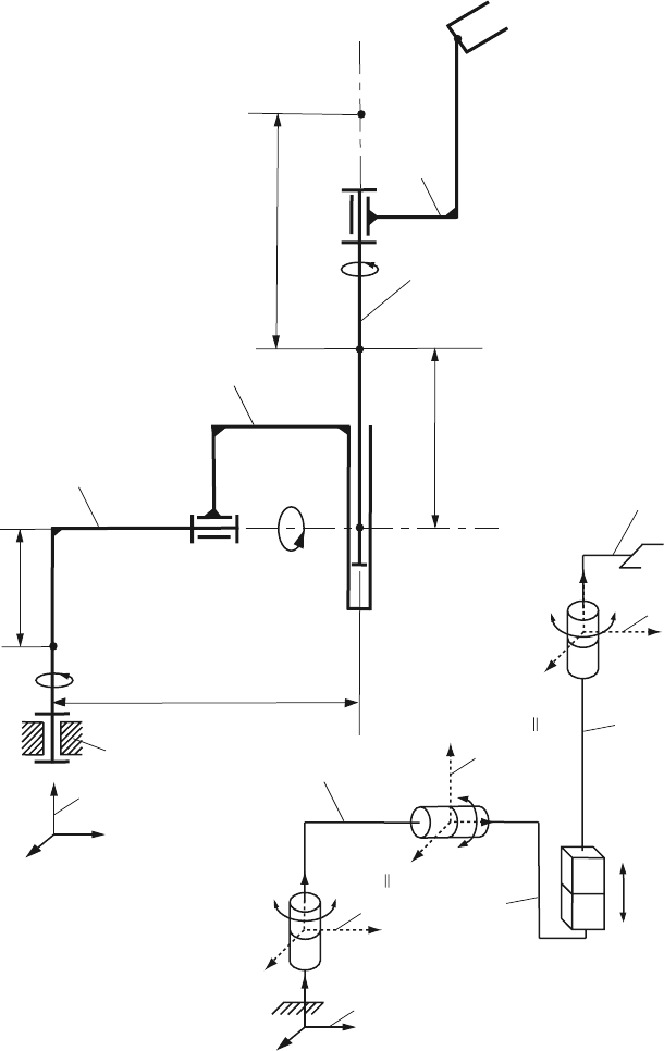
Figure 6.10 is a schematic representation of a robot (Kane and Levinson, 1983), with
four links 1, 2, 3, and 4. The mass center of the link i is designated C
i
, i = 1,2,3,4.
The dimensions AC
2
= L
1
, AC
1
= L
2
and C
3
C
4
= L
3
are shown in the figure. Link 1
rotates in a “fixed” Newtonian reference frame (0) about a vertical axis fixed in both
(0) and 1. The reference frame (0), RF0, has the unit vectors [ı
0
, j
0
, k
0
] as shown
in Fig. 6.10. The reference frame (1), RF1, of unit vectors [ı
1
, j
1
, k
1
] is attached to
link 1. The vertical unit vectors j
0
and j
1
are fixed in both (0) and 1.
The first generalized coordinate q
1
denotes the radian measure of the angle be-
tween the axes of (0) and (1). Link 1 supports link 2, and link 2 rotates relative to 1
about a horizontal axis fixed in both 1 and 2. The reference frame (2), RF2, of unit
vectors [ı
2
, j
2
, k
2
] is fixed in 2. The horizontal unit vectors ı
1
and ı
2
are fixed in both
1 and 2. The mass center C
2
is a point fixed in both 1 and 2.
The second generalized coordinate q
2
denotes the radian measure of the angle
between the axes of (1) and (2). The link 2 supports link 3, and link 3 has a transla-
tional motion relative to 2.
The generalized coordinate q
4
is the distance between the mass centers, C
2
and
C
3
, of 2 and 3, respectively. The link 3 supports link 4, and link 4 rotates relative to
3 about an axis fixed in both 3 and 4. The reference frame (4), RF4, of unit vectors
[ı
4
, j
4
, k
4
] is fixed in 4. The unit vectors j
2
and j
4
are fixed in both 3 and 4. The mass
center C
4
is a point fixed in both 3 and 4.
The generalized coordinate q
3
is the radian measure of the rotation angle between
3 and 4. The reference frame (4), [ı
4
, j
4
, k
4
] is fixed in 4 in such a way that ı
0
=
ı
4
, j
0
= j
4
, k
4
= k
0
when q
1
= q
2
= q
3
= 0.
The generalized speeds, u
1
, u
2
, u
3
, u
4
, are associated with the motion of a system,
and can be introduced as
u
1
= ω
40
·ı
4
,
u
2
= ω
40
·j
4
,
u
3
= ω
40
·k
4
,
u
4
= ˙q
4
, (6.45)
where
ω
40
denotes the angular velocity of 4 in (0). One may verify that
ω
40
=(˙q
1
s
2
s
3
+ ˙q
2
c
3
)ı
4
+(˙q
1
c
2
+ ˙q
3
)j
4
+(−˙q
1
s
2
c
3
+ ˙q
2
s
3
)k
4
, (6.46)
where s
i
and c
i
denote sinq
i
and cosq
i
, i = 1, 2, 3, respectively. Substitution into
Eq. 6.45 then yields
u
1
= ˙q
1
s
2
s
3
+ ˙q
2
c
3
,
u
2
= ˙q
1
c
2
+ ˙q
3
,
u
3
= −˙q
1
s
2
c
3
+ ˙q
2
s
3
,
u
4
= ˙q
4
. (6.47)
258 6 Analytical Dynamics of Open Kinematic Chains
1
L
1
C
1
q
1
0
0
k
0
0
j
ı
(0)
C
3
C
2
2
3
4
C
4
L
3
q
3
q
2
q
4
L
2
Schematic representation
of the robot in 3
-D
q
2
q
1
0
0
k
0
j
ı
(0)
1
1
ı
j
(1)
2
2
ı
j
(2)
4
ı
(4)
k
1
k
2
4
j
k
4
1
2
3
4
2
j
2
ı
4
j
1
ı
q
3
q
4
A
Fig. 6.10 RRTR robot arm

6.6 RRTR Robot Arm 259
Equation 6.47 can be solved uniquely for ˙q
1
, ˙q
2
, ˙q
3
, ˙q
4
. Specifically,
˙q
1
=(u
1
s
3
−u
3
c
3
)/s
2
,
˙q
2
=(u
1
c
3
+ u
3
s
3
),
˙q
3
= u
2
+(u
3
c
3
−u
1
s
3
)c
2
/s
2
,
˙q
4
= u
4
, (6.48)
with singularities at q
2
= 0
◦
and q
2
= 180
◦
degrees posing no problem. Thus, u
r
as
defined in Eq. 6.45 form a set of generalized speeds for the robot. The mass of link
r is m
r
, r = 1, 2, 3, 4. The central inertia dyadic of link r, can be expressed as
¯
I
r
=(I
rx
ı
r
)ı
r
+(I
ry
j
r
)j
r
+(I
rz
k
r
)k
r
, (6.49)
where I
rx
, I
ry
, I
rz
are the central principal moments of inertia of r = 1, 2, 3, 4.
In the case of the robot, there are two kinds of forces that contribute to the gen-
eralized active forces Q
r
, r = 1, 2, 3, 4 namely, contact forces applied in order to
drive links 1, 2, 3, 4, and gravitational forces exerted on the links.
Considering, the contact forces, the set of such forces transmitted from the New-
tonian frame (0) to link 1 (through bearings and by means of a motor) is replaced
with a couple of torque T
01
together with a force F
01
applied to 1 at C
1
.
Similarly, the set of contact forces transmitted from 2 to 1 is replaced with a
couple of torque T
21
together with a force F
21
applied to 1 at C
2
(which is a point
fixed in 1). The law of action and reaction then guarantees that the set of contact
forces transmitted from 1 to 2 is equivalent to a couple of torque −T
21
together
with the force −F
21
applied to 2 at C
2
.
Next, the set of contact forces exerted on 2 by 3 is replaced with a couple of
torque T
32
together with a force F
32
applied to 2 at C
32
, the point of 2 instanta-
neously coinciding with C
3
. The set of forces exerted by 2 on 3 is, therefore equiv-
alent to a couple torque −T
32
together with the force −F
32
applied to 3 at C
3
.
Similarly, torque T
43
and forces F
43
come into play in connection with the inter-
actions of 3 and 4 at C
4
. As for gravitational forces exerted on the links of the robot
by the Earth, these are denoted by G
r
, r = 1, 2, 3, 4, respectively.
The following notations are introduced
T
01y
= T
01
·j
1
= k
1
(q
1 f
−q
1
) −k
2
˙q
1
,
T
21x
= T
21
·ı
2
= k
3
(q
2
−q
2 f
)+k
4
˙q
2
+ g[(m
3
+ m
4
)q
4
+ m
4
L
3
]s
2
,
T
43y
= T
43
·j
3
= T
43
·j
2
= k
5
(q
3
−q
3 f
)+k
6
˙q
3
,
F
32y
= F
32
·j
3
= F
32
·j
2
= k
7
(q
4
−q
4 f
)+k
8
˙q
4
−g(m
3
+ m
4
)c
2
, (6.50)
where k
1
,..., k
8
are constant gains k
1
= 3.0 N m, k
2
= 5.0 N m s, k
3
= 1.0 N m, k
4
=
3.0 N m s, k
5
= 0.3 N m, k
6
=0.6Nms,k
7
=30Nm,k
8
= 41 N s, and q
rf
= π/3
rad r = 1, 2, 3, while q
4 f
= 0.1 m.
The initial numerical data are L
1
= 0.1 m, L
2
= 0.1 m, L
3
= 0.7 m, m
1
= 9 kg,
m
2
= 6 kg, m
3
= 4 kg, m
4
= 1 kg, I
1x
= 0.01 kg m
2
, I
1y
= 0.02 kg m
2
, I
1z
= 0.01 kg
260 6 Analytical Dynamics of Open Kinematic Chains
m
2
, I
2x
= 0.06 kg m
2
, I
2y
= 0.01 kg m
2
, I
2z
= 0.05 kg m
2
, I
3x
= 0.4 kg m
2
, I
3y
= 0.01
kg m
2
, I
3z
= 0.4 kg m
2
, I
4x
= 0.0005 kg m
2
, I
4y
= 0.001 kg m
2
, and I
4z
= 0.001 kg m
2
.
Kane’s Dynamical Equations
The numerical data are introduced with the MATLAB statements:
L1=0.1; L2=0.1; L3=0.7;
m1=9.; m2=6.; m3=4.; m4=1.;
I1x=0.01; I1y=0.02; I1z=0.01;
I2x=0.06; I2y=0.01; I2z=0.05;
I3x=0.4; I3y=0.01; I3z=0.4;
I4x=0.0005; I4y=0.001; I4z=0.001;
k1=3.; k2=5.; k3=1.; k4=3.; k5=0.3;
k6=0.6; k7=30.; k8=41.; g=9.8;
q1f=pi/3; q2f=pi/3; q3f=pi/3; q4f=0.1;
The MATLAB commands for the generalized coordinates are:
syms t real
q1 = sym(’q1(t)’);
q2 = sym(’q2(t)’);
q3 = sym(’q3(t)’);
q4 = sym(’q4(t)’);
The transformation matrix from RF2 to RF1 is
R
21
=
⎡
⎣
10 0
0 c
2
s
2
0 −s
2
c
2
⎤
⎦
,
and the transformation matrix from RF4 to RF2 is
R
42
=
⎡
⎣
c
3
0 −s
3
01 0
s
3
0 c
3
⎤
⎦
.
The MATLAB commands for the transformation matrices are:
c2 = cos(q2); s2 = sin(q2);
c3 = cos(q3); s3 = sin(q3);
% transformation matrix from RF2 to RF1
R21 = [[1 0 0]; [0 c2 s2]; [0 -s2 c2]];
% transformation matrix from RF4 to RF2
R42 = [[c3 0 -s3]; [0 1 0]; [s3 0 c3]];

6.6 RRTR Robot Arm 261
The generalized speeds, u
1
, u
2
, u
3
, u
4
, are associated with the motion of a system,
and can be introduced with:
u1 = sym(’u1(t)’);
u2 = sym(’u2(t)’);
u3 = sym(’u3(t)’);
u4 = sym(’u4(t)’);
Equation 6.48 represents the derivatives, ˙q
1
, ˙q
2
, ˙q
3
, ˙q
4
, of the generalized coordi-
nates, function of the generalized speeds:
dq1 = (u1
*
s3-u3
*
c3)/s2;
dq2=u1
*
c3+u3
*
s3;
dq3 = u2+(u3
*
c3-u1
*
s3)
*
c2/s2;
dq4 = u4;
The Kane’s dynamical equations are expressed in terms of the generalized coor-
dinates q1, q2, q3, q4, the generalized speeds u1, u2, u3, u4, and the time
derivatives of the generalized speeds. Two lists are introduced for the derivatives of
the generalized coordinates and the derivatives of the generalized speeds:
qt={diff(q1,t),diff(q2,t),diff(q3,t),diff(q4,t),...
diff(u1,t),diff(u2,t),diff(u3,t),diff(u4,t)};
ut={dq1,dq2,dq3,dq4, ’du1’, ’du2’, ’du3’, ’du4’};
%qt ut
%------------------------
% diff(’q1(t)’,t) -> dq1
% diff(’q2(t)’,t) -> dq2
% diff(’q3(t)’,t) -> dq3
% diff(’q4(t)’,t) -> dq4
% diff(’u1(t)’,t) -> ’du1’
% diff(’u2(t)’,t) -> ’du2’
% diff(’u3(t)’,t) -> ’du3’
% diff(’u4(t)’,t) -> ’du4’
Angular Velocities and Accelerations
The angular velocities of each link 1, 2, 3, 4, in RF0, involving the generalized
speeds, are expressed using a vector basis fixed in the body under consideration. The
angular velocity of link 1 with respect to RF0 expressed in terms of RF1 [ı
1
, j
1
, k
1
]
is
ω
10
= ˙q
1
j
1
, or:
w101 = [0, dq1, 0];

262 6 Analytical Dynamics of Open Kinematic Chains
The angular velocity of link 1 relative to RF0 expressed in terms of RF2 [ı
2
, j
2
, k
2
]
is:
w102 = w101
*
transpose(R21);
The angular velocity of link 2 relative to RF1 expressed in terms of RF1 [ı
1
, j
1
, k
1
]
is
ω
21
= ˙q
2
ı
1
, or:
w211 = [dq2, 0, 0];
The angular velocity of link 2 relative to RF1 expressed in terms of RF2 [ı
2
, j
2
, k
2
]
is
ω
21
= ˙q
2
ı
2
, or:
w212 = [dq2, 0, 0];
and the angular velocity of link 2 with respect to RF0 expressed in terms of RF2
[ı
2
, j
2
, k
2
] is ω
20
= ω
10
+ ω
21
, or:
w202 = w102 + w212;
The angular velocity of link 2 relative to RF0 expressed in terms of RF4 [ı
4
, j
4
, k
4
]
is:
w204 = w202
*
transpose(R42);
The angular velocity of link 3 with respect to RF0 expressed in terms of RF2
[ı
2
, j
2
, k
2
] is ω
30
= ω
20
, or:
w302 = w202;
The angular velocity of link 4 relative to RF2 expressed in terms of RF2 [ı
2
, j
2
, k
2
]
is
ω
42
= ˙q
3
j
2
, or:
w422 = [0, dq3, 0];
The angular velocity of link 4 with respect to RF2 expressed in terms of RF4
[ı
4
, j
4
, k
4
] is:
w424 = w422
*
transpose(R42);
The anglar velocity of link 4 with respect to RF0 expressed in terms of RF4
[ı
4
, j
4
, k
4
] is ω
40
= ω
20
+ ω
42
, or:
w404 = w204 + w424;
6.6 RRTR Robot Arm 263
The angular acceleration of link 1 with respect to RF0 expressed in terms of RF1
[ı
1
, j
1
, k
1
] is α
10
=
˙
ω
10
, or:
alpha101 = subs(diff(w101, t), qt, ut);
The angular acceleration of link 2 with respect to RF0 expressed in terms of RF2
[ı
2
, j
2
, k
2
] is α
20
=
˙
ω
20
, or:
alpha202 = subs(diff(w202, t), qt, ut);
The angular acceleration of link 3 with respect to RF0 expressed in terms of RF2
[ı
2
, j
2
, k
2
] is:
alpha302 = alpha202;
The anglar acceleration of link 4 with respect to RF0 expressed in terms of RF4
[ı
4
, j
4
, k
4
] is α
40
=
˙
ω
40
, or:
alpha404 = subs(diff(w404, t), qt, ut);
Remark: The angular velocity
ω
10
(w101) was expressed in terms of RF1, ω
20
(w202) was expressed in terms of RF2, ω
30
(w302) was expressed in terms of
RF3=RF2, and
ω
40
(w404) was expressed in terms of RF4.
The partial velocity
∂
ω
10
∂ u
r
will be in terms of RF1,
∂
ω
20
∂ u
r
will be in terms of
RF2,
∂
ω
30
∂ u
r
will be in terms of RF3, and
∂
ω
40
∂ u
r
will be in terms of RF4.
The central principal axes of inertia of link 1 are parallel to [ı
1
, j
1
, k
1
], link 2
are parallel to [ı
2
, j
2
, k
2
], link 3 are parallel to [ı
2
, j
2
, k
2
], and link 4 are parallel to
[ı
4
, j
4
, k
4
].
The angular velocities of each link are expressed using a vector basis fixed in the
body under consideration because the central principal axes of inertia of the body
are parallel to the vector basis fixed in the body.
For the velocities of C
1
, C
2
, C
3
, C
4
, the mass centers of links 1, 2, 3, 4, it is not
necessarily useful to work with RF1 in the case of velocity of C
1
, with RF2 for the
velocity of C
2
, and so forth. As an alternative, it is convenient to use any vector basis
that permits one to write the simplest expression.
Linear Velocities and Accelerations
The linear velocity of mass center C
1
of link 1 is zero since C
1
is fixed in RF0:
vC101 = [0, 0, 0];

264 6 Analytical Dynamics of Open Kinematic Chains
The position vector from C
1
, the mass center of link 1, to C
2
, the mass center of link
2, expressed in terms of RF1 [ı
1
, j
1
, k
1
] is r
C
1
C
2
= L
1
ı
1
+ L
2
j
1
, or:
rC121 = [L1, L2, 0];
The linear velocity of mass center C
2
of link 2 with respect to RF0 expressed in
terms of RF1 [ı
1
, j
1
, k
1
] is
v
C
2
=
d
dt
r
C
1
C
2
=
(1)
d
dt
r
C
1
C
2
+ ω
10
×r
C
1
C
2
,
or:
vC201 = diff(rC121, t) + cross(w101, rC121);
The velocity of C
2
, which is “fixed” in RF1 can be computed also as:
vC201 = cross(w101, [L1, 0, 0]);
The linear velocity of the mass center C
2
of link 2 with respect to RF0 expressed in
terms of RF2 [ı
2
, j
2
, k
2
] is:
vC202 = vC201
*
transpose(R21);
The position vector from C
1
, the mass center of link 1, to C
3
, the mass center of link
3, expressed in terms of RF2 [ı
2
, j
2
, k
2
] is r
C
1
C
3
= r
C
1
C
2
+ q
4
j
2
, or:
rC132 = [L1, L2, 0]
*
transpose(R21) + [0, q4, 0];
The linear velocity of mass center C
3
of link 3 with respect to RF0 expressed in
terms of RF2 [ı
2
, j
2
, k
2
] is
v
C
3
=
d
dt
r
C
1
C
3
=
(2)
d
dt
r
C
1
C
3
+ ω
20
×r
C
1
C
3
,
or:
vC302 = subs(diff(rC132,t),qt,ut)+cross(w202,rC132);
Another way of computing the previous velocity is:
vC302 = vC202+diff([0,q4,0],t]+cross(w202,[0,q4,0]);
The linear velocity of point C
32
of link 2 with respect to RF0 expressed in terms of
RF2 [ı
2
, j
2
, k
2
] is
v
C
32
= v
C
2
+ ω
20
×r
C
2
C
3
.

6.6 RRTR Robot Arm 265
The MATLAB command for v
C
32
is:
vC3202 = vC202 + cross(w202, [0, q4, 0]);
The point C
32
, of link 2, is superposed with the mass center C
3
, of link 3. The linear
velocity of mass center C
4
of link 4 with respect to RF0 expressed in terms of RF2
[ı
2
, j
2
, k
2
] is
v
C
4
= v
C
3
+ ω
20
×L
3
j
2
,
or:
vC402 = vC302 + cross(w202, [0, L3, 0]);
The linear acceleration of mass center C
1
of link 1 with respect to RF0 expressed in
terms of RF1 [ı
1
, j
1
, k
1
] is:
aC101 = [0, 0, 0];
The linear acceleration of mass center C
2
of link 2 with respect to RF0 expressed in
terms of RF1 [ı
1
, j
1
, k
1
] is
a
C
2
=
d
dt
v
C
2
=
(1)
d
dt
v
C
2
+ ω
10
×v
C
1
,
or:
aC201 = subs(diff(vC201, t),qt,ut)+cross(w101,vC201);
The linear acceleration of mass center C
3
of link 3 with respect to RF0 expressed in
terms of RF2 [ı
2
, j
2
, k
2
] is
a
C
3
=
d
dt
v
C
3
=
(2)
d
dt
v
C
3
+ ω
20
×v
C
3
,
or:
aC302 = subs(diff(vC302,t),qt,ut)+cross(w202,vC302);
The linear acceleration of mass center C
4
of link 4 with respect to RF0 expressed in
terms of RF2 [ı
2
, j
2
, k
2
] is
a
C
4
=
d
dt
v
C
4
=
(2)
d
dt
v
C
4
+ ω
40
×v
C
4
,
266 6 Analytical Dynamics of Open Kinematic Chains
The MATLAB command for a
C
4
is:
aC402 = subs(diff(vC402,t),qt,ut)+cross(w402,vC402);
The partial velocities with respect to u
r
(u1, u2, u3, u4) are
∂
ω
10
∂ u
r
,
∂
ω
20
∂ u
r
,
∂
ω
40
∂ u
r
,
∂ v
C
1
∂ u
r
,
∂ v
C
2
∂ u
r
,
∂ v
C
3
∂ u
r
,
∂ v
C
4
∂ u
r
,
∂ v
C
32
∂ u
r
,
r = 1, 2, 3, 4,
and in MATLAB are calculated using the function deriv:
w1
1 = deriv(w101, u1); w1 2 = deriv(w101, u2);
w1
3 = deriv(w101, u3); w1 4 = deriv(w101, u4);
w2
1 = deriv(w202, u1); w2 2 = deriv(w202, u2);
w2
3 = deriv(w202, u3); w2 4 = deriv(w202, u4);
w4
1 = deriv(w404, u1); w4 2 = deriv(w404, u2);
w4
3 = deriv(w404, u3); w4 4 = deriv(w404, u4);
vC1
1 = deriv(vC101, u1); vC1 2 = deriv(vC101, u2);
vC1
3 = deriv(vC101, u3); vC1 4 = deriv(vC101, u4);
vC2
1 = deriv(vC201, u1); vC2 2 = deriv(vC201, u2);
vC2
3 = deriv(vC201, u3); vC2 4 = deriv(vC201, u4);
vC3
1 = deriv(vC302, u1); vC3 2 = deriv(vC302, u2);
vC3
3 = deriv(vC302, u3); vC3 4 = deriv(vC302, u4);
vC4
1 = deriv(vC402, u1); vC4 2 = deriv(vC402, u2);
vC4
3 = deriv(vC402, u3); vC4 4 = deriv(vC402, u4);
vC32
1 = deriv(vC3202, u1);
vC32
2 = deriv(vC3202, u2);
vC32
3 = deriv(vC3202, u3);
vC32
4 = deriv(vC3202, u4);
Generalized Active Forces
Link 1
The following symbolical variables are introduced:
syms F01x F01y F01z T01x T01y T01z real
syms F21x F21y F21z T21x T21y T21z real