Dan B. Marghitu, Mechanisms and Robots Analysis with MATLAB®
Подождите немного. Документ загружается.

7.1 Problem Set: Mechanisms 287
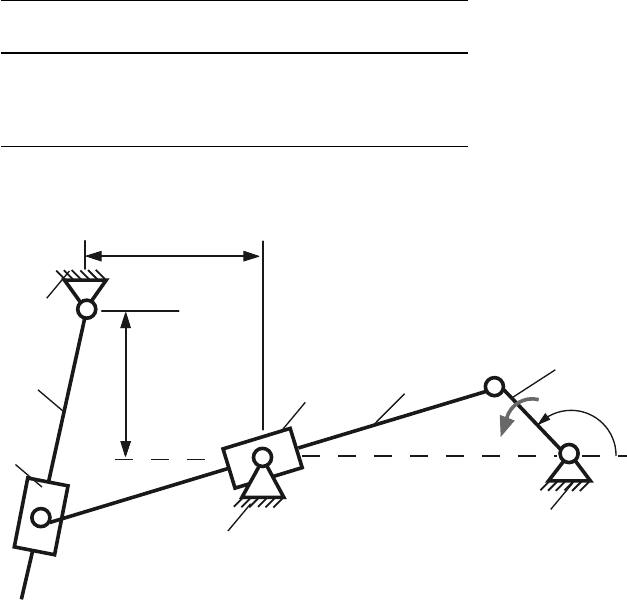
Table 7.12 Mechanism 12
No AB AC BD a b φ n
[m] [m] [m] [m] [m] [
◦
] [rpm]
1 0.12 0.30 0.50 0.08 0.15 60 500
2 0.10 0.30 0.50 0.07 0.12 150 700
3 0.09 0.30 0.45 0.06 0.10 240 900
4 0.08 0.25 0.40 0.05 0.09 330 1100
0
φ
A
1
D
C
B
E
3
2
4
5
0
0
n
b
a
Fig. 7.12 Mechanism 12
288 7 Problems
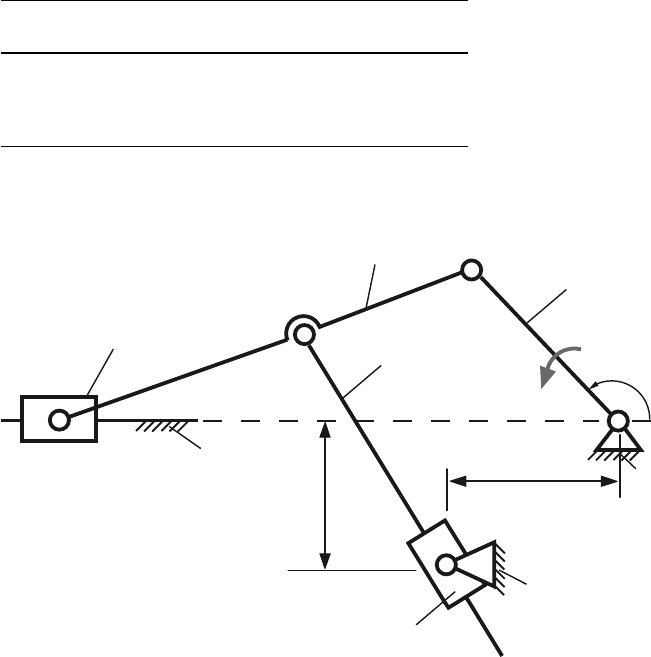
Table 7.13 Mechanism 13
No AB BC CD a b φ n
[m] [m] [m] [m] [m] [
◦
] [rpm]
1 0.20 0.21 0.39 0.30 0.25 45 500
2 0.18 0.17 0.35 0.27 0.26 135 1000
3 0.10 0.25 0.15 0.225 0.30 240 1500
4 0.22 0.23 0.45 0.30 0.32 315 2000
3
4
φ
A
1
2
B
D
0
5
C
0
n
0
a
b
E
Fig. 7.13 Mechanism 13
7.1 Problem Set: Mechanisms 289
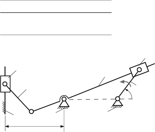
Table 7.14 Mechanism 14
No AB AC CD DE a φ n
[m] [m] [m] [m] [m] [
◦
] [rpm]
1 0.10 0.20 0.12 0.08 0.13 20 500
2 0.08 0.15 0.10 0.10 0.12 110 600
3 0.15 0.30 0.20 0.14 0.25 200 700
4 0.07 0.15 0.10 0.06 0.11 290 800
5
4
B
2
C
0
φ
A
1
0
n
0
3
D
E
a
Fig. 7.14 Mechanism 14
290 7 Problems
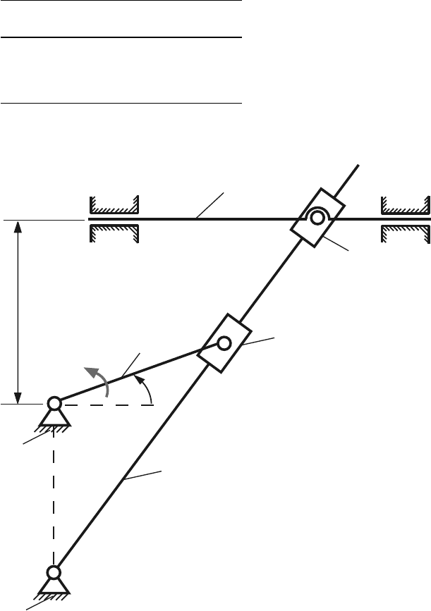
Table 7.15 Mechanism 15
No AB AC a φ n
[m] [m] [m] [
◦
] [rpm]
1 0.04 0.10 0.08 60 500
2 0.05 0.10 0.07 120 600
3 0.08 0.10 0.09 210 700
4 0.08 0.20 0.10 330 800
4
2
3
1
B
φ
A
0
0
0
C
0
D
a
5
n
Fig. 7.15 Mechanism 15

7.2 Problem Set: Robots 291
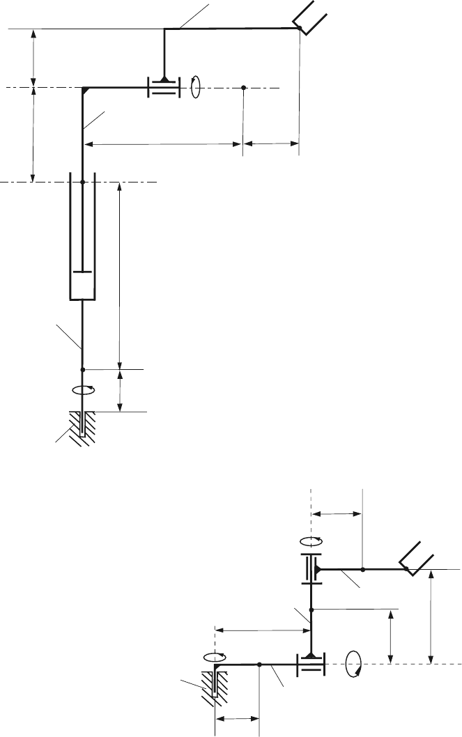
7.2 Problem Set: Robots
Schematic representations of a robot arm consisting of three links 1, 2, and 3 are
shown in Figs. 7.16–7.25. The mass centers of links 1, 2, and 3 are C
1
, C
2
, and C
3
,
respectively. The generalized coordinates (quantities associated with the instanta-
neous position of the system) are q
1
(t), q
2
(t), and q
3
(t).
The central principal axes of link p, p = 1,2,3 are parallel to ı
p
, j
p
, k
p
and the
associated moments of inertia have the values I
px
, I
py
, I
pz
, respectively. The central
inertia dyadic of link p is
¯
I
p
=(I
px
ı
p
)ı
p
+(I
py
j
p
)j
p
+(I
pz
k
p
)k
p
.
If the joint between link p and link p + 1isa
rotational joint consider a control vector moment
T
p,p+1
= T
(p,p+1)x
ı
p+1
+ T
(p,p+1)y
j
p+1
+ T
(p,p+1)z
k
p+1
,
translational joint consider a control vector force
F
p,p+1
= F
(p,p+1)x
ı
p+1
+ F
(p,p+1)y
j
p+1
+ F
(p,p+1)z
k
p+1
.
Select suitable numerical values for the input numerical data.
1. Find the transformation matrices R
ij
.
2. Calculate the angular velocities and accelerations of the links,
ω
ij
and α
ij
.
3. Determine the position vectors, r
C
i
, the velocities, v
C
i
, and the accelerations, a
C
i
of the mass centers C
i
.
4. Find the generalized (active) forces Q
i
.
5. Write a MATLAB program for the symbolical calculation of Lagrange’s equa-
tions of motion or/and Kane’s dynamical equations.
6. Find the numerical solutions for inverse dynamics and direct dynamics.
292 7 Problems
q
1
q
2
q
3
3
2
1
0
B
A
C
D
AC
1
= C
1
B = BC
2
= C
2
C = CC
3
= C
3
D = L
C
1
C
2
C
3
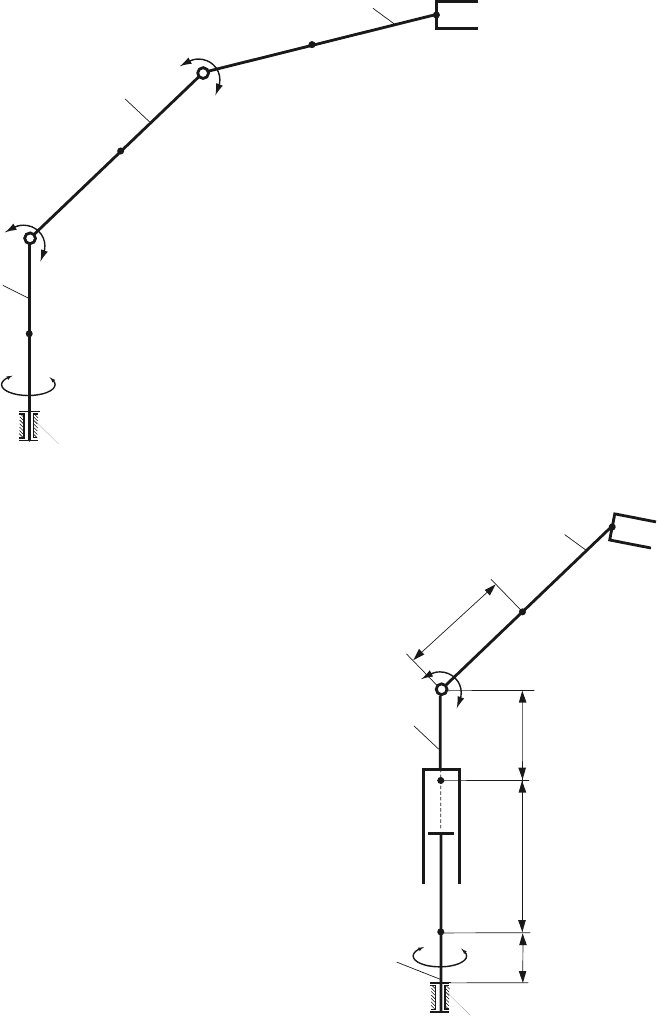
Fig. 7.16 Robot 1
Fig. 7.17 Robot 2
q
1
q
3
3
2
1
0
B
A
C
q
2
C
1
C
2
L
C
3
2
L
3
L
1
3
BC =2L
7.2 Problem Set: Robots 293
q
1
q
2
q
3
3
2
1
0
B
A
C
C
1
C
2
C
3
L
1
L
2
L
3
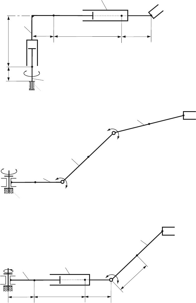
Fig. 7.18 Robot 3
q
1
q
2
q
3
3
2
1
0
B
A
C
D
C
1
C
2
C
3
AC
1
= C
1
B = BC
2
= C
2
C = CC
3
= C
3
D = L
Fig. 7.19 Robot 4
C
1
q
3
3
A
B
q
1
q
2
2
C
1
C
2
C
3
L
1
L
2
L
3
3
BC =2L
Fig. 7.20 Robot 5
294 7 Problems
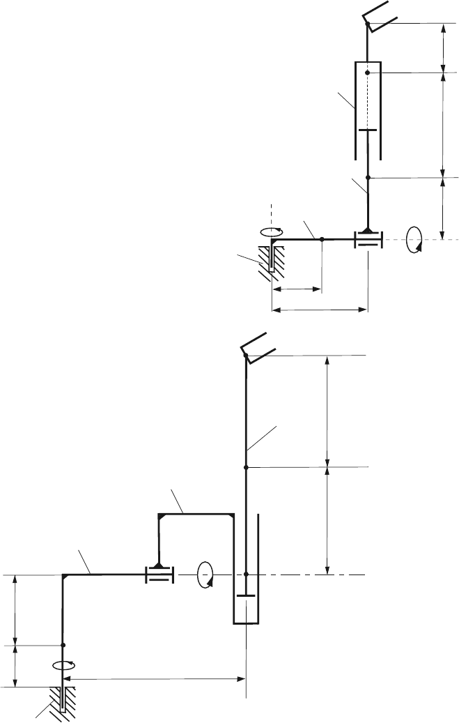
Fig. 7.21 Robot 6
q
3
2
0
C
q
1
A
q
2
B
1
3
L
1
L
L
3
B
C
1
C
2
C
3
L
4
L
1
C
1
q
1
C
3
C
2
2
3
q
2
L
3
0
1
q
3
L
2
L
4
Fig. 7.22 Robot 7
7.2 Problem Set: Robots 295
Fig. 7.23 Robot 8
1
C
1
q
1
0
C
2
2
3
C
3
q
3
q
2
L
1
L
3
L
2
L
4
296 7 Problems
1
C
1
q
1
0
C
2
2
3
C
3
q
3
q
2
L
3
L
2
L
1
L
4
L
5
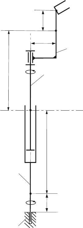
Fig. 7.24 Robot 9
Fig. 7.25 Robot 10
0
q
1
A
1
q
3
B
C
2
3
D
q
2
L
1
L
B
C
1
L
3
L
C
C
2
C
3
L
2
3
CD=2L