Dan B. Marghitu, Mechanisms and Robots Analysis with MATLAB®
Подождите немного. Документ загружается.

6.6 RRTR Robot Arm 267
The force applied by base 0 to link 1 at C
1
expressed in terms of RF1 is F
01
=
F
01x
ı
1
+ F
01y
j
1
+ F
01z
k
1
, or:
F01 = [F01x F01y F01z];
The torque applied by base 0 to link 1 expressed in terms of RF1 is T
01
=
T
01x
ı
1
+ T
01y
j
1
+ T
01z
k
1
, or:
T01 = [T01x T01y T01z];
The force applied by link 2 to link 1 at C
2
expressed in terms of RF2 is F
21
=
F
21x
ı
2
+ F
21y
j
2
+ F
21z
k
2
, or:
F21 = [F21x F21y F21z];
The torque applied by link 2 to link 1 expressed in terms of RF2 is T
21
= T
21x
ı
2
+
T
21y
j
2
+ T
21z
k
2
, or:
T21 = [T21x T21y T21z];
The gravitational force that acts on link 1 at C
1
is G
1
= −m
1
gj
0
= −m
1
gj
1
, or:
G1=[0-m1
*
g 0];
The generalized active forces for link 1 are
Q
1r
=
∂
ω
10
∂ u
r
·(T
01
+ T
21
)+
∂ v
C
1
∂ u
r
·(G
1
+ F
01
)+
∂ v
C
2
∂ u
r
·F
21
, r = 1, 2, 3, 4.
The MATLAB statements for the generalized active forces for link 1 are:
Q1a1=w1
1
*
(T01.’+R21.’
*
T21.’)+vC1 1
*
(G1.’+F01.’)+...
vC2
1
*
R21.’
*
F21.’;
Q1a2=w1
2
*
(T01.’+R21.’
*
T21.’)+vC1 2
*
(G1.’+F01.’)+...
vC2
2
*
R21.’
*
F21.’;
Q1a3=w1
3
*
(T01.’+R21.’
*
T21.’)+vC1 3
*
(G1.’+F01.’)+...
vC2
3
*
R21.’
*
F21.’;
Q1a4=w1
4
*
(T01.’+R21.’
*
T21.’)+vC1 4
*
(G1.’+F01.’)+...
vC2
4
*
R21.’
*
F21.’;
Link 2
The following symbolical variables are introduced:
syms F32x F32y F32z T32x T32y T32z real
268 6 Analytical Dynamics of Open Kinematic Chains
The force applied by link 1 to link 2 at C
2
expressed in terms of RF2 is −F
21
.
The torque applied by link 1 to link 2 expressed in terms of RF2 is −T
21
. The
force applied by link 3 to link 2 at C
32
expressed in terms of RF2 is F
32
=
F
32x
ı
2
+ F
32y
j
2
+ F
32z
k
2
, or:
F32 = [F32x F32y F32z];
The torque applied by link 3 to link 2 expressed in terms of RF2 is T
32
= T
32x
ı
2
+
T
32y
j
2
+ T
32z
k
2
, or:
T32 = [T32x T32y T32z];
The gravitational force that acts on link 2 at C
2
expressed in terms of RF1 is
G
2
= −m
2
gj
1
, or:
G2=[0-m2
*
g 0];
The generalized active forces for link 2 are
Q
2r
=
∂
ω
20
∂ u
r
·(T
32
−T
21
)+
∂ v
C
2
∂ u
r
·(G
2
−F
21
)+
∂ v
C
32
∂ u
r
·F
32
, r = 1, 2, 3, 4.
The MATLAB statements for the generalized active forces for link 2 are:
Q2a1=w2
1
*
(T32.’-T21.’)+vC2 1
*
(G2.’-R21.’
*
F21.’)+...
vC32
1
*
F32.’;
Q2a2=w2
2
*
(T32.’-T21.’)+vC2 2
*
(G2.’-R21.’
*
F21.’)+...
vC32
2
*
F32.’;
Q2a3=w2
3
*
(T32.’-T21.’)+vC2 3
*
(G2.’-R21.’
*
F21.’)+...
vC32
3
*
F32.’;
Q2a4=w2
4
*
(T32.’-T21.’)+vC2 4
*
(G2.’-R21.’
*
F21.’)+...
vC32
2
*
F32.’;
Link 3
The following symbolical variables are introduced:
syms F43x F43y F43z T43x T43y T43z real
The force applied by link 2 to link 3 at C
3
expressed in terms of RF2 is −F
32
.
The torque applied by link 2 to link 3 expressed in terms of RF2 is −T
32
. The
force applied by link 4 to link 3 at C
4
expressed in terms of RF2 is F
43
=
F
43x
ı
2
+ F
43y
j
2
+ F
43z
k
2
, or:
F43 = [F43x F43y F43z];
6.6 RRTR Robot Arm 269
The torque applied by link 4 to link 3 expressed in terms of RF2 is T
43
= T
43x
ı
2
+
T
43y
j
2
+ T
43z
k
2
, or:
T43 = [T43x T43y T43z];
The gravitational force that acts on link 3 at C
3
expressed in terms of RF2 is:
G3=[0-m3
*
g0]
*
transpose(R21);
The generalized active forces for link 3 are
Q
3r
=
∂
ω
20
∂ u
r
·(T
43
−T
32
)+
∂ v
C
3
∂ u
r
·(G
3
−F
32
)+
∂ v
C
4
∂ u
r
·F
43
, r = 1, 2, 3, 4.
The MATLAB statements for the generalized active forces for link 3 are:
Q3a1=w2
1
*
(T43.’-T32.’)+vC3 1
*
(G3.’-F32.’)+...
vC4
1
*
F43.’;
Q3a2=w2
2
*
(T43.’-T32.’)+vC3 2
*
(G3.’-F32.’)+...
vC4
2
*
F43.’;
Q3a3=w2
3
*
(T43.’-T32.’)+vC3 3
*
(G3.’-F32.’)+...
vC4
3
*
F43.’;
Q3a4=w2
4
*
(T43.’-T32.’)+vC3 4
*
(G3.’-F32.’)+...
vC4
4
*
F43.’;
Link 4
The force applied by link 3 to link 4 at C
4
expressed in terms of RF2 is −F
43
. The
torque applied by link 3 to link 4 expressed in terms of RF2 is −T
43
. The gravita-
tional force that acts on link 4 at C
4
expressed in terms of RF2 is:
G4=[0-m4
*
g0]
*
transpose(R21);
The generalized active forces for link 3 are
Q
4r
=
∂
ω
40
∂ u
r
·(−T
43
)+
∂ v
C
4
∂ u
r
·(G
4
−F
43
), r = 1, 2, 3, 4.
The MATLAB statements for the generalized active forces for link 4 are:
Q4a1 = w4
1
*
R42
*
(-T43).’ + vC4 1
*
(G4.’-F43.’);
Q4a2 = w4
2
*
R42
*
(-T43).’ + vC4 2
*
(G4.’-F43.’);
Q4a3 = w4
3
*
R42
*
(-T43).’ + vC4 3
*
(G4.’-F43.’);
Q4a4 = w4
4
*
R42
*
(-T43).’ + vC4 4
*
(G4.’-F43.’);

270 6 Analytical Dynamics of Open Kinematic Chains
The total generalized active forces are
Q
r
= Q
1r
+ Q
2r
+ Q
3r
+ Q
4r
, r = 1, 2, 3, 4,
or:
Q1 = simple(Q1a1+Q2a1+Q3a1+Q4a1);
Q2 = simple(Q1a2+Q2a2+Q3a2+Q4a2);
Q3 = simple(Q1a3+Q2a3+Q3a3+Q4a3);
Q4 = simple(Q1a4+Q2a4+Q3a4+Q4a4);
Generalized Inertia Forces
The central inertia dyadic of link p, p = 1, 2, 3, 4is
¯
I
p
=(I
px
ı
p
)ı
p
+(I
py
j
p
)j
p
+
(I
pz
k
p
)k
p
. The central principal axes of link p are parallel to ı
p
, j
p
, k
p
and the
associated moments of inertia have the values I
px
, I
py
, I
pz
, respectively. The inertia
matrix associated with
¯
I
p
is
¯
I
p
→
⎡
⎣
I
px
00
0 I
py
0
00I
pz
⎤
⎦
,
or in MATLAB:
% inertia matrix associated with
% central inertia dyadic of link 1
I1 = [I1x 0 0; 0 I1y 0; 0 0 I1z];
% inertia matrix associated with
% central inertia dyadic of link 2
I2 = [I2x 0 0; 0 I2y 0; 0 0 I2z];
% inertia matrix associated with
% central inertia dyadic of link 3
I3 = [I3x 0 0; 0 I3y 0; 0 0 I3z];
% inertia matrix associated with
% central inertia dyadic of link 4
I4 = [I4x 0 0; 0 I4y 0; 0 0 I4z];
Define F
in p
, the inertia force for link p,as
F
in p
= −m
r
a
C
p
, p = 1, 2, 3, 4,
or in MATLAB:
% inertia force Fin1 of link1 in RF0
% expressed in terms of RF1
Fin1 = -m1
*
aC101;
6.6 RRTR Robot Arm 271
% inertia force Fin2 of link2 in RF0
% expressed in terms of RF1
Fin2 = -m2
*
aC201;
% inertia force Fin3 of link3 in RF0
% expressed in terms of RF2
Fin3 = -m3
*
aC302;
% inertia force Fin4 of link4 in RF0
% expressed in terms of RF2
Fin4 = -m4
*
aC402;
The inertia moment M
in p
for link p is
M
in p
= −α
p0
·
¯
I
p
−ω
p0
×(
¯
I
p
·ω
p0
).
The MATLAB statements for the inertia moments are:
% inertia moment Min1 of link 1 in RF0
% expressed in terms of RF1
Min1 = -alpha101
*
I1-cross(w101,w101
*
I1);
% inertia moment Min2 of link 2 in RF0
% expressed in terms of RF2
Min2 = -alpha202
*
I2-cross(w202,w202
*
I2);
% inertia moment Min3 of link 3 in RF0
% expressed in terms of RF2
Min3 = -alpha302
*
I3-cross(w202,w202
*
I3);
% inertia moment Min4 of link 4 in RF0
% expressed in terms of RF4
Min4 = -alpha404
*
I4-cross(w404,w404
*
I4);
The generalized inertia force K
inr
is
K
inr
=
4
∑
p=1
∂ ω
p0
∂ u
r
·M
in p
+
4
∑
p=1
∂ v
C
p
∂ u
r
·F
in p
, r = 1, 2, 3, 4.
The MATLAB commands for the generalized inertia forces are:
Kin1 = w1
1
*
Min1.’ + vC1 1
*
Fin1.’ + ...
w2
1
*
Min2.’ + vC2 1
*
Fin2.’ + ...
w2
1
*
Min3.’ + vC3 1
*
Fin3.’ + ...
w4
1
*
Min4.’ + vC4 1
*
Fin4.’ ;
Kin2 = w1
2
*
Min1.’ + vC1 2
*
Fin1.’ + ...
w2
2
*
Min2.’ + vC2 2
*
Fin2.’ + ...
w2
2
*
Min3.’ + vC3 2
*
Fin3.’ + ...
w4
2
*
Min4.’ + vC4 2
*
Fin4.’ ;

272 6 Analytical Dynamics of Open Kinematic Chains
Kin3 = w1 3
*
Min1.’ + vC1 3
*
Fin1.’ + ...
w2
3
*
Min2.’ + vC2 3
*
Fin2.’ + ...
w2
3
*
Min3.’ + vC3 3
*
Fin3.’ + ...
w4
3
*
Min4.’ + vC4 3
*
Fin4.’ ;
Kin4 = w1
4
*
Min1.’ + vC1 4
*
Fin1.’ + ...
w2
4
*
Min2.’ + vC2 4
*
Fin2.’ + ...
w2
4
*
Min3.’ + vC3 4
*
Fin3.’ + ...
w4
4
*
Min4.’ + vC4 4
*
Fin4.’ ;
The dynamical equations governing the robot arm are Q
r
+ K
inr
= 0, r = 1, 2, 3, 4.
Kane’s dynamical equations in MATLAB are:
Kane1 = Q1 + Kin1;
Kane2 = Q2 + Kin2;
Kane3 = Q3 + Kin3;
Kane4 = Q4 + Kin4;
Using the feedback control laws Kane’s equations have to be rewritten and in MAT-
LAB:
T01yc = k1
*
(q1f-q1)-k2
*
dq1;
T21xc = k3
*
(q2-q2f)+k4
*
dq2+g
*
((m3+m4)
*
q4+m4
*
L3)
*
s2;
T43yc = k5
*
(q3-q3f)+k6
*
dq3;
F32yc = k7
*
(q4-q4f)+k8
*
dq4-g
*
(m3+m4)
*
c2;
tor = {T01y , T21x , T43y , F32y };
torf = {T01yc, T21xc, T43yc, F32yc };
Kan1 = subs(Kane1, tor, torf);
Kan2 = subs(Kane2, tor, torf);
Kan3 = subs(Kane3, tor, torf);
Kan4 = subs(Kane4, tor, torf);
Kane’s dynamical equations are transformed into a first-order system of differential
equations:
ql = {q1, q2, q3, q4, u1, u2, u3, u4,};
qe = {’x(1)’,’x(2)’,’x(3)’,’x(4)’,...
’x(5)’,’x(6)’,’x(7)’,’x(8)’};
%ql qe
%------------------
% ’q1(t)’ -> ’x(1)’
% ’q2(t)’ -> ’x(2)’
% ’q3(t)’ -> ’x(3)’
6.6 RRTR Robot Arm 273
% ’q4(t)’ -> ’x(4)’
% ’u1(t)’ -> ’x(5)’
% ’u2(t)’ -> ’x(6)’
% ’u3(t)’ -> ’x(7)’
% ’u4(t)’ -> ’x(8)’
e1 = subs(Kan1, ql, qe);
e2 = subs(Kan2, ql, qe);
e3 = subs(Kan3, ql, qe);
e4 = subs(Kan4, ql, qe);
% system of ODE
dx1 = char(subs(dq1, ql, qe));
dx2 = char(subs(dq2, ql, qe));
dx3 = char(subs(dq3, ql, qe));
dx4 = char(subs(dq4, ql, qe));
dx5 = char(du1c);
dx6 = char(du2c);
dx7 = char(du3c);
dx8 = char(du4c);
The system of differential equations is solved numerically by m-file functions. The
function file, RRTR.m is created using the statements:
fid = fopen(’RRTR.m’,’w+’);
fprintf(fid,’function dx = RRTR(t,x)\n’);
fprintf(fid,’dx = zeros(8,1);\n’);
fprintf(fid,’dx(1) = ’); fprintf(fid,dx1);
fprintf(fid,’;\n’);
fprintf(fid,’dx(2) = ’); fprintf(fid,dx2);
fprintf(fid,’;\n’);
fprintf(fid,’dx(3) = ’); fprintf(fid,dx3);
fprintf(fid,’;\n’);
fprintf(fid,’dx(4) = ’); fprintf(fid,dx4);
fprintf(fid,’;\n’);
fprintf(fid,’dx(5) = ’); fprintf(fid,dx5);
fprintf(fid,’;\n’);
fprintf(fid,’dx(6) = ’); fprintf(fid,dx6);
fprintf(fid,’;\n’);
fprintf(fid,’dx(7) = ’); fprintf(fid,dx7);
fprintf(fid,’;\n’);
fprintf(fid,’dx(8) = ’); fprintf(fid,dx8);
fprintf(fid,’;’);
fclose(fid); cd(pwd);
274 6 Analytical Dynamics of Open Kinematic Chains
The ode45 solver is used for the system of differential equations:
t0 = 0; tf = 15; time = [0 tf];
q10=pi/6; q20=pi/12; q30=pi/10; q40=0.01;
u10=0; u20=0; u30=0; u40=0;
x0=[q10 q20 q30 q40 u10 u20 u30 u40];
[t,xs]=ode45(@RRTR, time, x0);
x1=xs(:,1); x2=xs(:,2); x3=xs(:,3); x4=xs(:,4);
x5=xs(:,5); x6=xs(:,6); x7=xs(:,7); x8=xs(:,8);
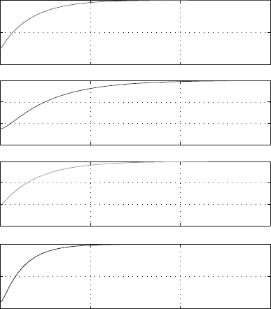
subplot(4,1,1),plot(t,x1
*
180/pi,’r’),...
xlabel(’t (s)’),ylabel(’q1 (deg)’),grid,...
subplot(4,1,2),plot(t,x2
*
180/pi,’b’),...
xlabel(’t (s)’),ylabel(’q2 (deg)’),grid,...
subplot(4,1,3),plot(t,x3
*
180/pi,’g’),...
xlabel(’t (s)’),ylabel(’q3 (deg)’),grid,...
subplot(4,1,4),plot(t,x4,’black’),...
xlabel(’t (s)’),ylabel(’q4 (m)’),grid
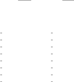
[ts,xs] = ode45(@RRTR,0:1:5,x0)
Figure 6.11 shows the plots of the generalized coordinates q
1
(t), q
2
(t), q
3
(t), and
q
4
(t). The MATLAB computer program for the robot arm using Kane’s dynamical
equations is given in Appendix E.6.
20
40
60
q1 (deg)
0
20
40
60
q2 (deg)
0
20
40
60
q3 (deg)
5
10
15
0
0.05
0.1
t (s)
q4 (m)
Fig. 6.11 Solution plots of the generalized coordinates q
1
(t), q
2
(t), q
3
(t), and q
4
(t)
Chapter 7
Problems
7.1 Problem Set: Mechanisms
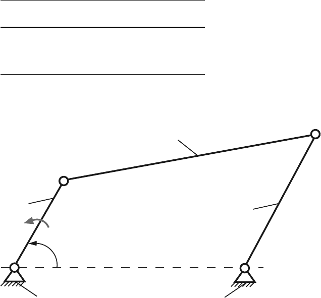
The dimensions of the planar mechanisms, shown in Figs. 7.1–7.15, are given in
Tables 7.1–7.15, respectively. The angle of the driver link 1 with the horizontal axis
is φ. The constant angular speed of the driver link 1 is n and is given in the tables.
1. Determine the type of motion (rotation, translation, and complex motion) for
each link, the connectivity table, the structural diagram, the contour diagram, the
independent contours, the number of degrees of freedom, the dyads, and the type
of the dyads.
2. Find the positions of the joints and the angles of the links with the horizontal
axis when the angle of the driver link 1 with the horizontal axis is φ. Write a
MATLAB
R
program for the positions of the mechanism for the given angle φ .
3. Write a MATLAB program for the positions of the mechanism for a complete
rotation of the driver link 1, φ ∈ [0
◦
,..., 360
◦
], using different methods.
4. Write a MATLAB program for the path of a point on a link with general plane
motion.
5. Write a MATLAB program for the animation (movie) of the mechanism for a
complete rotation of the driver link 1, φ ∈ [0
◦
,..., 360
◦
].
6. Find the velocities and the accelerations of the mechanism, using different meth-
ods, for the given position when the driver link 1 makes an angle φ with the
horizontal axis. The constant angular speed of the driver link 1 is n. Write a
MATLAB program for this.
7. The link bars of the mechanism are homogeneous rectangular prisms with the
width h = 0.01 m and the depth d = 0.001 m. The sliders have the width w
Slider
=
0.050 m, the height h
Slider
= 0.020 m, and the same depth d = 0.001 m. The links
of the mechanism are homogeneous and are made of steel having a mass density
ρ
Steel
= 8000 kg/m
3
. The gravitational acceleration is g = 9.807 m/s
2
. The driver
link 1 has a constant angular speed n. The external force or moment applied on
the last link 5 is opposed to the motion of the link and has the value: |F
5ext
| =
275
276 7 Problems
2000 N if the last link 5 has a translational motion or, |M
5ext
| = 3000 N m if the
last link 5 has a rotational motion.
Determine the joint forces and the motor moment M
m
required for the dynamic
equilibrium of the considered mechanism when the the driver link 1 makes an
angle φ with the horizontal axis. Write MATLAB programs for different methods
of calculating the dynamical forces.
Table 7.1 Mechanism 1
No AB AD BC CD φ n
[m] [m] [m] [m] [
◦
] [rpm]
1 0.08 0.19 0.21 0.12 60 500
2 0.10 0.24 0.26 0.14 120 600
3 0.18 0.43 0.47 0.27 210 700
4 0.15 0.36 0.40 0.21 330 800
1
A
n
φ
C
B
D
2
3
0
0
Fig. 7.1 Mechanism 1