Dake L.P. Fundamentals of reservoir engineering
Подождите немного. Документ загружается.


IMMISCIBLE DISPLACEMENT 381
complex displacement problems using the assumption of segregated flow, these
include gravity drainage and bottom water coning.
In this section a great deal of attention has been focussed on the presentation of
approximate analytical methods for predicting oil recovery resulting from segregated
displacement. In reading the remainder of this chapter, however, the main point to
keep in mind is that the description of segregated flow in one dimension necessitates
the use of linear, averaged relative permeability functions, irrespective of whether the
displacement is stable or not. It is this fact which facilitated the derivation of such
simple recovery formulae.
10.7 ALLOWANCE FOR THE EFFECT OF A FINITE CAPILLARY TRANSITION ZONE IN
DISPLACEMENT CALCULATIONS
For the displacement of oil by water, exercises 10.2 and 10.3 clearly demonstrate the
sensitivity of the calculated oil recovery, as a function of time, to the assumed water
saturation distribution in the dip-normal direction. So far, too extreme notions of this
distribution have been considered; the uniform distribution (diffuse flow) and that due to
fluid segregation. From the information provided in the two exercises it is not possible
for the engineer to decide which, if either, of the assumed saturation distributions is
appropriate to describe the displacement. One vital piece of data has been omitted and
that is the capillary pressure curve and, in particular, the thickness of the capillary
transition zone.
If h is the reservoir thickness and H the thickness of the capillary transition zone then
the water saturation distribution can be approximated as uniform or segregated
depending on whether
H >> h (uniform)
H << h (segregated)
If the reservoir is very thin in comparison to the capillary transition zone the saturation
in the advancing water flood will appear to be uniformly distributed with respect to
thickness, fig. 10.7. On the other hand, if the transition zone is of negligible thickness
compared to the reservoir then it will appear that the oil and water are segregated.
Linear relative permeability curves can be used to describe such displacement.
The question then arises of how to describe oil displacement in a homogeneous
reservoir when the capillary transition zone is of the same order of magnitude as the
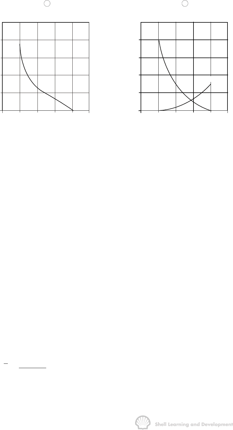
reservoir thickness (H ≈ h). Consider, for instance, the capillary pressure curve shown
in fig. 10.27(a) in which the capillary pressure difference across the transition zone is
3 psi.
IMMISCIBLE DISPLACEMENT 382
P (psi)
c
5
4
3
2
1
0
0
.2 .4
.6 .8 1.0
50
40
30
20
10
0
z (ft)
a
k
rw
1.0
.8
.6
.4
.2
0
0
.2 .4
.6 .8 1.0
k
ro
b
OIL
WATER
S
w
S
w
Fig. 10.27 (a) Imbibition capillary pressure curve, and (b) laboratory measured relative
permeabilities (rock curves,- table 10.1)
If oil displacement in the horizontal reservoir described in exercises 10.2 and 10.3 is re-
examined using this capillary pressure curve, then, since γ
w
= 1.04 and γ
o
= 0.81; the
capillary pressure versus capillary rise equation, (10.6), applied in the differential form
dP
c
= .4335 ∆γ dz
gives the relationship
dP
c
= .4335 (1.04−.81) dz = 0.1 dz (10.62)
Thus for dP
c
= 3 psi the height of the capillary transition zone is 30 ft which, since the
reservoir is 40 ft thick, means that neither diffuse nor segregated flow conditions can
be assumed to govern the displacement. Instead, it is necessary to generate averaged
relative permeability curves, which are functions of the thickness averaged water
saturation, and use these in the oil recovery calculations.
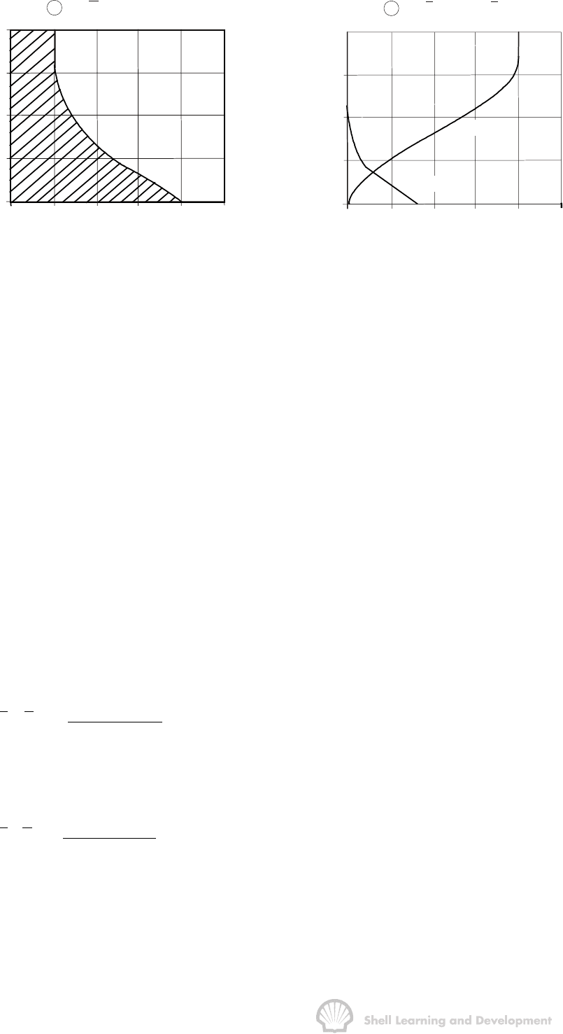
The manner in which this is done is illustrated graphically in fig. 10.28. Consider first of
all fig. 10.28(a). This represents the water saturation distribution, at any point in the
displacement path, as a function of thickness. For this initial case the maximum water
saturation, S
w
= 1−S
or
(P
c
= 0), is assumed to be at the base of the reservoir, above
which the saturation is distributed in accordance with the saturation-capillary rise
function, fig. 10.27(a). Since the reservoir is homogeneous, the thickness averaged
water saturation can be expressed mathematically as
h
w
0
w
S(z)dz
S
h
=
ò
(10.63)
IMMISCIBLE DISPLACEMENT 383
40
30
20
10
0
0
.2 .4
.6 .8 1.0
S
w
a
S
w
= .357
z
(ft)
40
30
20
10
0
0
.2 .4
.6 .8 1.0
k
r
bk
rw
= .047; k
ro
= .481
z
(ft)
k
ro
(z)
k
rw
(z)
Fig. 10.28 (a) Water saturation, and (b) relative permeability distributions, with
respect to thickness when the saturation at the base of the reservoir is
S
w
= 1 −
−−
− S
or
(P
c
=0)
which can be evaluated graphically by measuring the shaded area to the left and
beneath the saturation-thickness function, fig. 10.28(a), and dividing this by the total
height, h = 40 ft. For this initial saturation distribution S
w
= 0.357.
The rock relative permeabilities presented in table 10.1, which have been used in
exercises 10.2 and 10.3, are plotted as fig. 10.27(b). As already mentioned, these
represent point relative permeabilities in the reservoir and are dependent on the water
saturation at the point in question. Therefore, since there is a defined water saturation
distribution in the reservoir, fig. 10.28(a), there must also be a relative permeability
distribution, with respect to thickness, for both oil and water. These distributions can be
determined by selecting a particular height in the reservoir and reading the water
saturation at that point from fig. 10.28(a). For this saturation the corresponding point
relative permeabilities are read from fig. 10.27 (b). These relative permeability
distributions are listed in table 10.9 and plotted in fig. 10.28(b).
Mathematically, the thickness averaged relative permeabilities are
h
rw w
0
rw
w
k(S(z))dz
k(S)
h
=
ò
(10.64)
and
h
ro w
0
ro
o
k(S(z))dz
k(S)
h
=
ò
(10.65)

IMMISCIBLE DISPLACEMENT 384
z
ft
S
w
fig.10.28(a)
k
rw
fig.10.28(b)
k
ro
fig.10.28(b)
0 .800 .300 0
5 .650 .170 .055
10 .470 .060 .195
15 .350 .020 .370
20 .275 .006 .540
25 .225 .002 .690
30 .200 0 .800
40 .200 0 .800
TABLE 10.9
Water saturation and point relative permeability distributions as functions
of the reservoir thickness; fig.10.28(a) and (b).
Graphically these values can be determined by measuring the area to the left of each
curve in fig. 10.28(b) and dividing by the total thickness. For this initial saturation
distribution,
ro
w
k(S)= 0.047 and
ro
w
k(S)= 0.481
After all this work all that has been obtained is one value of the thickness averaged
saturation
w
S and the corresponding values of thickness averaged water and oil
relative permeabilities
rw
w
k(S) and
ro
w
k(S). These three values are only relevant for
the initial assumption that the maximum water saturation has reached the base of the
reservoir at the point in question.
The next stage in generating averaged relative permeability curves is to allow the
maximum water saturation, S
w
= 1−S
or
, to rise by an arbitrary amount and recalculate
the new thickness averaged water saturation and relative permeabilities corresponding
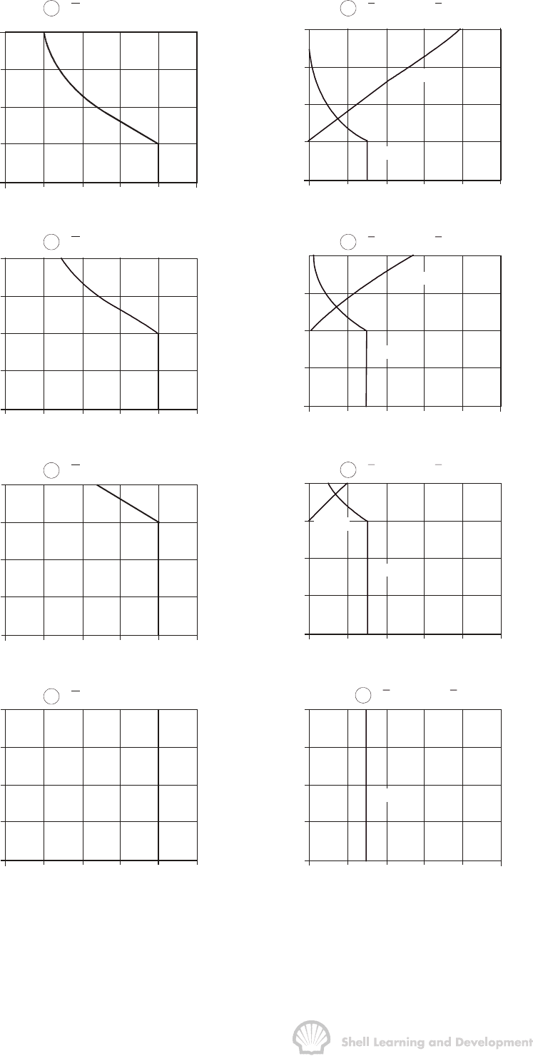
to the new water saturation distribution. This process is illustrated in fig. 10.29 in which
the maximum water saturation is allowed to rise in 10 foot increments. Physically this
corresponds to a series of saturation distributions observed at a fixed point in the
reservoir as the flood passes that point. The main assumption which permits the
drawing of the saturation distributions, shown in fig.10.29 (a)−(h), is that of vertical
equilibrium described in sec. 10.2. This implies that as the average water saturation at
the point of observation increases, the water and oil are instantaneously distributed in
accordance with capillary-gravity equilibrium. Thus in fig. 10.29(a), above the height of
10 feet, the capillary pressure curve, fig. 10.27(a), is retraced to give the appropriate
water saturation distribution.
For each height rise of the saturation, S
w
= 1−S
or
, relative permeability distributions
have also been plotted in fig. 10.29 and in each case values of S
w
,k
rw
w
S
and
ro
w
k(S)have been calculated by graphical integration, as described previously. These
average values are listed in table 10.10 and plotted in fig. 10.30 as the circled points.
IMMISCIBLE DISPLACEMENT 385
40
30
20
10
0
0
.2 .4
.6 .8 1.0
40
30
20
10
0
0
.2 .4
.6 .8 1.0
40
30
20
10
0
0
.2 .4
.6 .8 1.0
40
30
20
10
0
0
.2 .4
.6 .8 1.0
40
30
20
10
0
0
.2 .4
.6 .8 1.0
40
30
20
10
0
0
.2 .4
.6 .8 1.0
40
30
20
10
0
0
.2 .4
.6 .8 1.0
40
30
20
10
0
0
.2 .4
.6 .8 1.
0
S
w
S
w
S
w
S
w
k
r
k
r
k
r
k
r
a
S
w
= .504
c
S
w
= .648
e
S
w
= .756
g
S
w
= .800
z
(ft)
z
(ft)
z
(ft)
z
(ft)
z
(ft)
z
(ft)
z
(ft)
z
(ft)
b
k
rw
= .130 ; k
ro
= .280
d
kk
rw ro
= .203 ; = .120
h
kk
rw ro
= .300 ; = 0
k (z)
ro
k (z)
rw
k (z)
ro
k (z)
rw
k (z)
rw
f
kk
rw ro
= .269 ; = .025
k (z)
rw
k (z)
ro
Fig. 10.29 Water saturation and relative permeability distributions, as functions of
thickness, as the maximum saturation, S
w
= 1 −
−−
− S
or
, is allowed to rise in 10
foot increments in the reservoir

IMMISCIBLE DISPLACEMENT 386
w
S
rw
w
k(S)
ro
w
k(S)
c
P(psi)
°
.20 (S
wc
) 0 .8 5.0
.357 .047 .481 2.0
.504 .130 .280 1.0
.648 .203 .120 0
.756 .269 .025 -1.0
.800 .300 0 -2.0
TABLE 10.10
Thickness averaged saturations, relative permeabilities and pseudo capillary
pressures corresponding to figs. 10.28 and 10.29
The
rw
w
k(S)and
ro
w
k(S)relationships are the thickness averaged relative permeabilities
and will be referred to as such in the remainder of this chapter. In the literature they are
frequently called pseudo relative permeabilities, or simply "pseudo-curves". This author
feels, however, that there are already a sufficient number of "pseudos" in reservoir
engineering without introducing another to describe parameters derived from a simple
averaging process.
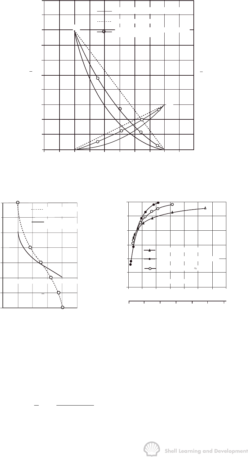
As might be expected the averaged relative permeability curves are intermediate
between the rock curves (H >> h) and the linear relations for segregated flow (H << h).
Using the averaged curves in effect reduces the description of the displacement
process from two to one dimension, along the centre line of the reservoir. The curves
can therefore be used in conjunction with the one dimensional Buckley Leverett theory
by drawing the corresponding fractional flow curve and applying the practical graphical
technique of Welge, described in sec. 10.5 and illustrated in exercise 10.2, to
determine oil recovery as a function of cumulative water injected and time. The results
obtained from such calculations, for the same linear reservoir model described in
exercises 10.2 and 10.3 and at the same injection rate of 1000 rb/d
(
µ
o
= 5 cp;
µ
w
= .5 cp), are shown in fig. 10.32 and again are intermediate between
those obtained assuming the diffuse flow condition (table 10.5; fig. 10.17) and
segregated flow (table 10.6; fig. 10.24).
The graphical technique for determining averaged relative permeabilities is rather
laborious and has only been included in this section for illustrative purposes. In practice
it is very easy to compute the functions using a simple computer program for which the
necessary input data include rock relative permeabilities and the capillary pressure
function. Average saturations and permeabilities can then be obtained by numerically
evaluating the integrals equs. (10.63-65) for different elevations of the maximum
saturation S
w
= 1−S
or
.
Also listed in table 10.10 are values of
c
P
°
the pseudo capillary pressure (a real
"pseudo"!). This is simply the phase pressure difference between the oil and water at
the centre of the reservoir and the relationship between pseudo capillary pressure and
thickness averaged water saturation, fig. 10.31, is called the pseudo capillary pressure
curve.
IMMISCIBLE DISPLACEMENT 387
DIFFUSE FLOW (ROCK CURVES)
SEGREGATED FLOW
INTERMEDIATE (FINITE CAPILLARY
TRANSITION ZONE)
1.0
.9
.8
.7
.6
.5
.4
.3
.2
.1
0
0 .1 .2.3.4 .5.6 .7.8.91.0
k
rw
k'
ro
k
ro
k'
rw
Fig. 10.30 Averaged relative permeability curves for a homogeneous reservoir, for
diffuse and segregated flow; together with the intermediate case when the
capillary transition zone is comparable to the reservoir thickness
PSEUDO CAPILLARY
PRESSURE
LABORATORY
MEASURED CURVE
5
4
3
2
1
0
-1
-2
.2
.4
.6 1.0.8
S
w
S
w
P
P°
(psi)
c
c
05101
5
20 2
5
30
time
(y
rs
)
0
0
12
3
4
56
7
.
6
.5
.4
.3
.2
.1
q; = 1000 rb / d
DIFFUSE FLOW (EX. 10.2)
SEGREGATED FLOW (EX. 10.3)
INTERMEDIATE (H h)
N
(PV)
pd
W (PV)
id
Fig. 10.31 Capillary and pseudo capillary
pressure curves.
Fig. 10.32 Comparison of oil recoveries for
different assumed water saturation
distributions during displacement.
Let p
o
and p
w
be the oil and water pressures at any point in a horizontal reservoir at an
elevation z above the base. If
o
p
°
and
w
p
°
are the corresponding pressures referred to
the centre line of the reservoir then, if the reservoir has a total thickness h, the relations
between p
o
and
o
p
°
, and p
w
and,
w
p
°
, under conditions of hydrostatic equilibrium, are
o
oo
6
g
h
pp z (Darcyunits)
21.013310
ρ
°
æö
=−−
ç÷
×
èø
and

IMMISCIBLE DISPLACEMENT 388
w
ww
6
gh
pp z ("")
21.013310
ρ
°
æö
=−−
ç÷
×
èø
Subtraction of these equations gives
owcc
6
gh
pp PP z (atm)
21.0133 10
ρ
°° °
∆
æö
−==+ −
ç÷
×
èø
(10.66)
or, converting to field units
owcc
h
p p P P 0.4335 z (psi)
2
γ
°° °
æö
−==+ ∆ −
ç÷
èø
(10.67)
It is convenient to choose the value of z to coincide with the position of the maximum
water saturation, S
w
= 1−S
or
, in the reservoir (i.e.
or
1S
zz
−
=
). At this point p
o
−p
w
= P
c
= 0
and equations (10.66) and (10.67) can be reduced to
or
c1S
6
gh
Pz
21.0133 10
ρ
°
−
∆
æö
=−
ç÷
×
èø
(10.68)
and
or
c1S
h
P0.4335 z
2
γ
°
−
æö
=∆−
ç÷
èø
(10.69)
respectively. Thus, in the reservoir being currently described (∆
γ
= 0.230; h = 40 ft.)
equ. (10.69) becomes
()
or
c1S
P0.120z
°
−
=− (10.70)
From equ. (10.70) it can be seen that the pseudo capillary pressure will vary between
2.0 psi and -2.0 psi as z, the position of the saturation S
w
= 1 − S
or
varies between
0 and 40 feet, as shown in fig. 10.33.
Pressure Pressure Pressure
Z
Z = 0
1 -S
P = 2 psi
°
c
P = -2 psi
°
c
P = 0
°
c
water
oil water
oil
wateroil
Z = 20ft
1 -S
Z = 40f
t
Z = 20ft
Z = 0
Z = 40ft
1 -S
or
or
or
Fig. 10.33 Variation in the pseudo capillary pressure between +2 and -2 psi as the
maximum water saturation S
w
= 1−
−−
−S
or
rises from the base to the top of the
reservoir

IMMISCIBLE DISPLACEMENT 389
Values of
c
P
°
as a function ofS
w
are listed in table 10.10, and the relationship plotted in
fig. 10.31. In particular, the maximum value of
c
P
°
is included for S
w
= S
wc
= .2, the
connate water saturation. In this case, the water saturation is also 0.2 at the base of
reservoir which, as shown in fig. 27(a), corresponds to a capillary pressure of at least
3 psi. Therefore the phase pressure difference at the centre of the reservoir must be, at
least,
c
P
°
= 5 psi.
Using the combination of averaged relative permeabilities and pseudo capillary
pressure a one dimensional fractional flow equation, representing the average flow
along the centre line of the reservoir, can be developed which is analogous to
equ. (10.9). The only difference will be that the rock relative permeabilities will be
replaced by averaged permeabilities and the capillary pressure gradient term
c
P
x
∂
∂
by
c
P
x
°
∂
∂
. And, just as the capillary pressure gradient was neglected in the oil
recovery calculations described in sec. 10.5, so too, the
c
P
x
°
∂
∂
term is neglected when
drawing the fractional flow curve for the present recovery calculations. The pseudo
capillary pressure-saturation relationship, however, plays an important role in
numerical reservoir simulation which will be described in sec. 10.10.
The methods presented in this section can also be applied in a dipping reservoir. The
averaging is again carried out in the dip normal direction with the result that the
capillary pressures, evaluated in this section as
dP
c
∝ dz
are replaced throughout by expressions of the form
dP
c
∝ cos
θ
dy
where z is measured vertically upwards and y in the dip-normal direction from the base
of the reservoir.
10.8 DISPLACEMENT IN STRATIFIED RESERVOIRS
So far, displacement has only been considered in homogeneous, linear reservoirs. In
stratified reservoirs in which there is a defined variation in reservoir parameters with
thickness, in the dip-normal direction, the description of displacement is necessarily
more complex. Nevertheless, the same basic method is used, as described in the
previous section, namely, to generate thickness averaged relative permeabilities as
functions of the thickness averaged water saturation. This will again reduce the
mathematical description to one dimension permitting the use of the Buckley Leverett
theory and the Welge graphical technique (sec. 10.5) for approximate calculations of
the oil recovery.
Two cases can be distinguished, which will both be dealt with in this section. Firstly,
when there is pressure communication between the individual sand layers and vertical
equilibrium pertains across the entire formation thickness and, secondly, when the

IMMISCIBLE DISPLACEMENT 390
individual sands are isolated from one another by impermeable shale layers so that
there is a total lack of pressure communication.
a) With pressure communication between the layers
Consider the case of a 40 ft. thick horizontal reservoir which can be subdivided into
three homogeneous layers each with different thickness, porosity and permeability, as
shown in fig.10.34.
layer 3
layer 2
layer 1
k = 200mD;
3
k = 100mD;
k = 50mD;
2
1
φ
3
= 0.20;
φ
φ
2
1
= 0.17;
= 0.15;
h = 10 ft.
3
h
h
2
1
= 20 ft.
= 10 ft.
h = 40 ft
.
Fig. 10.34 Example of a stratified, linear reservoir for which pressure communication
between the layers is assumed
If the water and oil again have specific gravities of 1.04 and 0.81, respectively then the
capillary pressure is related to capillary rise by the equation
dP
c
= 0.1 dz (psi) (10.62)
Similarly, the pseudo capillary pressure equation for calculating the phase pressure
difference at the centre of the reservoir is still
or
c1S
P0.1(20z )
−
°
=− (10.70)
where
or
1S
z
−
is the elevation of the maximum water saturation, S
w
= 1 − S
or
, in the
reservoir, at which point the phase pressure P
c
is always zero. Laboratory measured
relative permeabilities and capillary pressures for the three layers are shown in
fig. 10.35.
