Cohen I.M., Kundu P.K. Fluid Mechanics
Подождите немного. Документ загружается.

732 Compressible Flow
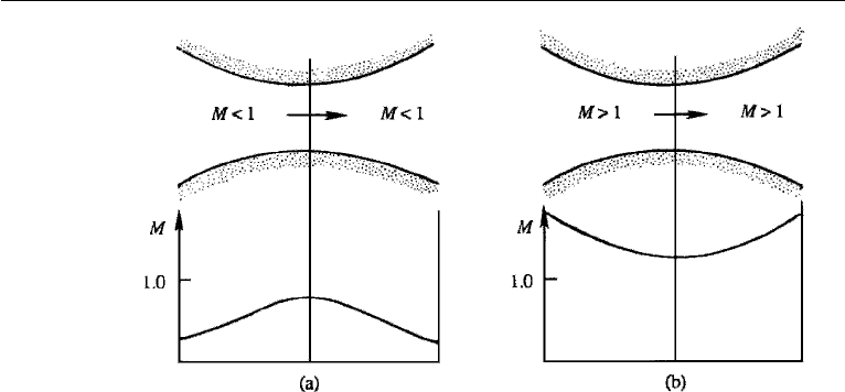
Figure 16.7 Convergent–divergent passages in which the condition at the throat is not sonic.
that the nozzle must converge in the subsonic portion and diverge in the supersonic
portion. Such a nozzle is called a convergent–divergent nozzle. From Figure 16.6 it
is clear that the Mach number must be unity at the throat, where the area is neither
increasing nor decreasing. This is consistent with equation (16.27), which shows that
du can be nonzero at the throat only if M = 1. It follows that the sonic velocity can
be achieved only at the throat of a nozzle or a diffuser and nowhere else.
It does not, however, follow that M must necessarily be unity at the throat.
According to equation (16.27), we may have a case where M = 1 at the throat if
du = 0 there. As an example, note that the flow in a convergent–divergent tube may
be subsonic everywhere, with M increasing in the convergent portion and decreas-
ing in the divergent portion, with M = 1 at the throat (Figure 16.7a). The first half
of the tube here is acting as a nozzle, whereas the second half is acting as a dif-
fuser. Alternatively, we may have a convergent–divergent tube in which the flow is
supersonic everywhere, with M decreasing in the convergent portion and increasing
in the divergent portion, and again M = 1 at the throat (Figure 16.7b).
Example 16.1
The nozzle of a rocket motor is designed to generate a thrust of 30,000 N when
operating at an altitude of 20 km. The pressure inside the combustion chamber is
1000 kPa while the temperature is 2500 K. The gas constant of the fluid in the jet is
R = 280 m
2
/(s
2
K), and γ = 1.4. Assuming that the flow in the nozzle is isentropic,
calculate the throat and exit areas. Use the isentropic table (Table 16.1).
Solution: At an altitude of 20 km, the pressure of the standard atmosphere
(SectionA4 in Appendix A) is 5467 Pa. If subscripts “0” and “e” refer to the stagnation
and exit conditions, then a summary of the information given is as follows:
p
e
= 5467 Pa,
p
0
= 1000 kPa,

6. Normal Shock Wave 733
T
0
= 2500 K,
Thrust = ρ
e
A
e
u
2
e
= 30,000 N.
Here, we have used the facts that the thrust equals mass flow rate times the exit velocity,
and the pressure inside the combustion chamber is nearly equal to the stagnation
pressure. The pressure ratio at the exit is
p
e
p
0
=
5467
(1000)(1000)
= 5.467 ×10
−3
.
For this ratio of p
e
/p
0
, the isentropic table (Table 16.1) gives
M
e
= 4.15,
A
e
A
∗
= 12.2,
T
e
T
0
= 0.225.
The exit temperature and density are therefore
T
e
= (0.225)(2500) = 562 K,
ρ
e
= p
e
/RT
e
= 5467/(280)(562) = 0.0347 kg/ m
3
.
The exit velocity is
u
e
= M
e
γRT
e
= 4.15
(1.4)(280)(562) = 1948 m/s.
The exit area is found from the expression for thrust:
A
e
=
Thrust
ρ
e
u
2
e
=
30,000
(0.0347)(1948)
2
= 0.228 m
2
.
Because A
e
/A
∗
= 12.2, the throat area is
A
∗
=
0.228
12.2
= 0.0187 m
2
.
6. Normal Shock Wave
A shock wave is similar to a sound wave except that it has finite strength. The thickness
of such a wavefront is of the order of micrometers, so that the properties vary almost
discontinuously across a shock wave. The high gradients of velocity and temperature
result in entropy production within the wave, due to which the isentropic relations
734 Compressible Flow
cannot be used across the shock. In this section we shall derive the relations between
properties of the flow on the two sides of a normal shock, where the wavefront is
perpendicular to the direction of flow. We shall treat the shock wave as a discontinuity;
a treatment of Navier-Strokes shock structure is given at the end of this section.
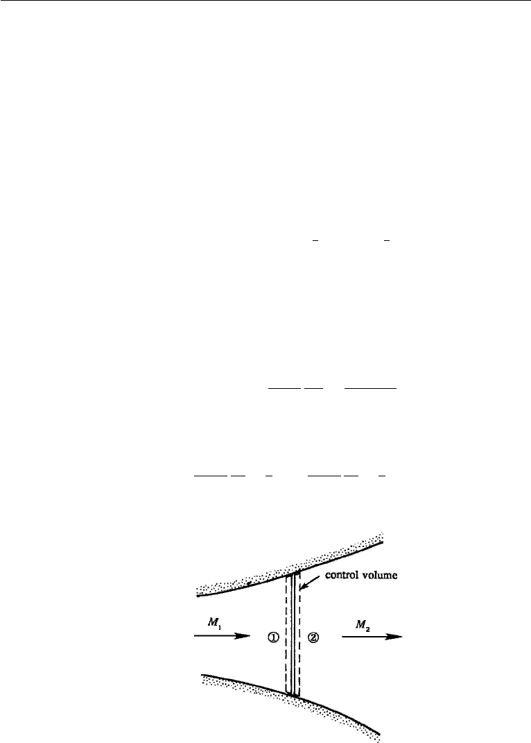
To derive the relationships between the properties on the two sides of the shock,
consider a control volume shown in Figure 16.8, where the sections 1 and 2 can
be taken arbitrarily close to each other because of the discontinuous nature of the
wave. The area change between the upstream and the downstream sides can then be
neglected. The basic equations are
Continuity: ρ
1
u
1
= ρ
2
u
2
, (16.28)
x-momentum: p
1
− p
2
= ρ
2
u
2
2
− ρ
1
u
2
1
, (16.29)
Energy: h
1
+
1
2
u
2
1
= h
2
+
1
2
u
2
2
.
In the application of the momentum theorem, we have neglected any frictional drag
from the walls because such forces go to zero as the wave thickness goes to zero.
Note that we cannot use the Bernoulli equation because the process inside the wave is
dissipative. We have written down four unknowns (h
2
, u
2
, p
2
, ρ
2
) and three equations.
The additional relation comes from the perfect gas relationship
h = C
p
T =
γR
γ − 1
p
ρR
=
γp
(γ − 1)ρ
,
so that the energy equation becomes
γ
γ − 1
p
1
ρ
1
+
1
2
u
2
1
=
γ
γ − 1
p
2
ρ
2
+
1
2
u
2
2
. (16.30)
Figure 16.8 Normal shock wave.

6. Normal Shock Wave 735
We now have three unknowns (u
2
, p
2
, ρ
2
) and three equations (16.28)–(16.30).
Elimination of ρ
2
and u
2
from these gives, after some algebra,
p
2
p
1
= 1 +
2γ
γ + 1
ρ
1
u
2
1
γp
1
− 1
.
This can be expressed in terms of the upstream Mach number M
1
by noting that
ρu
2
/γp = u
2
/γ RT = M
2
. The pressure ratio then becomes
p
2
p
1
= 1 +
2γ
γ + 1
(M
2
1
− 1). (16.31)
Let us now derive a relation between M
1
and M
2
. Because ρu
2
= ρc
2
M
2
=
ρ(γp/ρ)M
2
= γpM
2
, the momentum equation (16.29) gives
p
1
+ γp
1
M
2
1
= p
2
+ γp
2
M
2
2
.
Using equation (16.31), this gives
M
2
2
=
(γ − 1)M
2
1
+ 2
2γM
2
1
+ 1 − γ
,
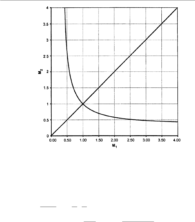
(16.32)
which is plotted in Figure 16.9. Because M
2
= M
1
(state 2 = state 1) is a solution
of equations (16.28)–(16.30), that is shown as well indicating two possible solutions
for M
2
for all M
1
> [(γ −1)/2γ ]
1/2
. We show in what follows that M
1
1toavoid
violation of the second law of thermodynamics. The two possible solutions are: (a) no
change of state; and (b) a sudden transition from supersonic to subsonic flow with
consequent increases in pressure, density, and temperature. The density, velocity, and
temperature ratios can be similarly obtained. They are
ρ
2
ρ
1
=
u
1
u
2
=
(γ + 1)M
2
1
(γ − 1)M
2
1
+ 2
, (16.33)
T
2
T
1
= 1 +
2(γ − 1)
(γ + 1)
2
γM
2
1
+ 1
M
2
1
(M
2
1
− 1). (16.34)
The normal shock relations (16.31)–(16.34) were worked out independently by
the British engineer W. J. M. Rankine (1820–1872) and the French ballistician
Pierre Henry Hugoniot (1851–1887). These equations are sometimes known as the
Rankine–Hugoniot relations.
736 Compressible Flow
Figure 16.9 Normal shock-wave solution M
2
(M
1
) for γ = 1.4. Trivial (no change) solution is also
shown. Asymptotes are [(γ − 1)/2γ ]
1/2
= 0.378.
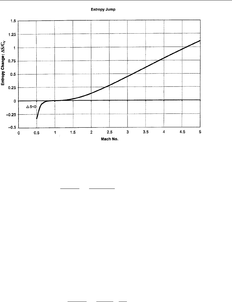
An important quantity is the change of entropy across the shock. Using equa-
tion (16.4), the entropy change is
S
2
− S
1
C
v
= ln
p
2
p
1
ρ
1
ρ
2
γ
= ln
1 +
2γ
γ + 1
(M
2
1
− 1)
(γ − 1)M
2
1
+ 2
(γ + 1)M
2
1
γ
, (16.35)
which is plotted in Figure 16.10. This shows that the entropy across an expansion
shock would decrease, which is impermissible for the perfect gas equation of state.
However, for a heavy fluorocarbon gas (FC-70), Fergason et al. (2001), using different
equations of state, have numerically simulated a rarefaction (expansion) shock in a
shock tube type flow. Equation (16.36) calculates the entropy change for a perfect gas
with constant specific heats explicitly in the neighborhood of M
1
= 1. Now assume
that the upstream Mach number M
1
is only slightly larger than 1, so that M
2
1
− 1is
6. Normal Shock Wave 737
Figure 16.10 Entropy change (S
2
−S
1
)/C
v
as a function of M
1
for γ = 1.4. Note higher-order contact
at M = 1.
a small quantity. It is straightforward to show that equation (16.35) then reduces to
(Exercise 2)
S
2
− S
1
C
v
2γ(γ − 1)
3(γ + 1)
2
(M
2
1
− 1)
3
. (16.36)
This shows that we must have M
1
> 1 because the entropy of an adiabatic
process cannot decrease. Equation (16.32) then shows that M
2
< 1. Thus, the
Mach number changes from supersonic to subsonic values across a normal shock;
a discontinuous change from subsonic to supersonic conditions would lead to a
violation of the second law of thermodynamics. (A shock wave is therefore anal-
ogous to a hydraulic jump (Chapter 7, Section 12) in a gravity current, in which
the Froude number jumps from supercritical to subcritical values; see Figure 7.23.)
Equations (16.31), (16.33), and (16.34) then show that the jumps in p, ρ, and T
are also from low to high values, so that a shock wave compresses and heats
a fluid.
Note that the terms involving the first two powers of (M
2
1
− 1) do not appear in
equation (16.36). Using the pressure ratio (16.31), equation (16.36) can be written as
S
2
− S
1
C
v
γ
2
− 1
12γ
2
p
p
1
3
.
This shows that as the wave amplitude decreases, the entropy jump goes to zero
much faster than the rate at which the pressure jump (or the jumps in velocity
or temperature) goes to zero. Weak shock waves are therefore nearly isentropic.
738 Compressible Flow
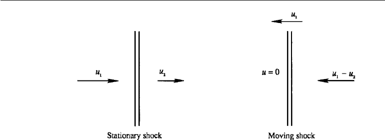
Figure 16.11 Stationary and moving shocks.
This is why we argued that the propagation of sound waves is an isentropic
process.
Because of the adiabatic nature of the process, the stagnation properties T
0
and
h
0
are constant across the shock. In contrast, the stagnation properties p
0
and ρ
0
decrease across the shock due to the dissipative processes inside the wavefront.
Normal Shock Propagating in a Still Medium
Frequently, one needs to calculate the properties of flow due to the propagation
of a shock wave through a still medium, for example, due to an explosion. The
transformation necessary to analyze this problem is indicated in Figure 16.11. The
left panel shows a stationary shock, with incoming and outgoing velocities u
1
and u
2
,
respectively. On this flow we add a velocity u
1
directed to the left, so that the fluid
entering the shock is stationary, and the fluid downstream of the shock is moving to
the left at a speed u
1
−u
2
, as shown in the right panel of the figure. This is consistent
with our remark in Section 2 that the passage of a compression wave “pushes” the
fluid forward in the direction of propagation of the wave. The shock speed is therefore
u
1
, with a supersonic Mach number M
1
= u
1
/c
1
> 1. It follows that a finite pres-
sure disturbance propagates through a still fluid at supersonic speed, in contrast to
infinitesimal waves that propagate at the sonic speed. The expressions for all the ther-
modynamic properties of the flow, such as those given in equations (16.31)–(16.36),
are still applicable.
Shock Structure
We shall now note a few points about the structure of a shock wave. The viscous and
heat conductive processes within the shock wave result in an entropy increase across
the front. However, the magnitude of the viscosity µ and thermal conductivity k only
determines the thickness of the front and not the magnitude of the entropy increase.
The entropy increase is determined solely by the upstream Mach number as shown
by equation (16.36). We shall also see later that the wave drag experienced by a body
due to the appearance of a shock wave is independent of viscosity or thermal con-
ductivity. (The situation here is analogous to the viscous dissipation in fully turbulent

6. Normal Shock Wave 739
flows (Chapter 13, Section 8), in which the dissipation rate ε is determined by the
velocity and length scales of a large-scale turbulence field (ε ∼ u
3
/l) and not by the
magnitude of the viscosity; a change in viscosity merely changes the scale at which
the dissipation takes place (namely, the Kolmogorov microscale).)
The shock wave is in fact a very thin boundary layer. However, the velocity
gradient du/dx is entirely longitudinal, in contrast to the lateral velocity gradient
involved in a viscous boundary layer near a solid surface. Analysis shows that the
thickness δ of a shock wave is given by
δu
ν
∼ 1,
where the left-hand side is a Reynolds number based on the velocity change across
the shock, its thickness, and the average value of viscosity. Taking a typical value for
air of ν ∼ 10
−5
m
2
/s, and a velocity jump of u ∼ 100 m/s, we obtain a shock
thickness of
δ ∼ 10
−7
m.
This is not much larger than the mean free path (average distance traveled by a
molecule between collisions), which suggests that the continuum hypothesis becomes
of questionable validity in analyzing shock structure.
To gain some insight into the structure of shock waves, we shall consider the
one-dimensional steady Navier–Stokes equations, including heat conduction and
Newtonian viscous stresses. Despite the fact that the significant length scale for the
structure pushes the limits of validity of the continuum formulation, the solution we
obtain provides a smooth transition between upstream and downstream states, looks
reasonable, and agrees with experiments and kinetic theory models for upstream Mach
numbers less than about 2. The equations for conservation of mass, momentum, and
energy are, respectively,
d(ρu)/dx = 0
ρudu/dx + dp/dx = d(µ
du/dx)/dx, µ
= 2µ + λ
ρudh/dx − udp/dx = µ
(du/dx)
2
+ d(kdT/dx)/dx.
By adding to the energy equation the product of u with the momentum equation, these
can be integrated once to yield,
ρu = m
mu + p − µ
du/dx = mV
m(h + u
2
/2) − µ
udu/dx − kdT /dx = mI,
where m, V , I are the constants of integration. These are evaluated upstream (state 1)
and downstream (state 2) where gradients vanish and yield the Rankine-Hugoniot
relations derived above. We also need the equations of state for a perfect gas with
constant specific heats to solve for the structure: h = C
p
T,p = ρRT . Multiplying
the energy equation by C
p
/k we obtain the form
(mC
p
/k)(C
p
T + u
2
/2) − (µ
C
p
/k)d(u
2
/2)/dx − d(C
p
T )/dx = mC
p
I/k.
740 Compressible Flow
This has an exact integral in the special case Pr
≡ µ
C
p
/k = 1. This was found by
Becker in 1922. If Stokes relation is assumed [(4.42)], 3λ +2µ = 0 then µ
= 4µ/3
and Pr = µC
p
/k = 3/4, which is quite close to the actual value for air. The Becker
integral is C
p
T + u
2
/2 = I . Eliminating all variables but u from the momentum
equation, using the equations of state, mass conservation, and the energy integral,
mu + (m/u)(R/C
p
)(I − u
2
/2) − µ
du/dx = mV .
With C
p
/R = γ /(γ − 1), multiplying by u/m, we obtain
−[2γ /(γ + 1)](µ
/m)udu/dx =−u
2
+[2γ /(γ + 1)]uV − 2I(γ − 1)/(γ + 1)
≡ (U
1
− U )(U − U
2
)
Divide by V
2
and let u/V = U . The equation for the structure becomes
−U(U
1
− U)
−1
(U − U
2
)
−1
dU =[(γ + 1)/2γ ](m/µ
)dx,
where the roots of the quadratic are
U
1,2
=[γ /(γ + 1)]{1 ±[1 − 2(γ
2
− 1)I /(γ
2
V
2
)]
1/2
},
the dimensionless speeds far up- and downstream of the shock. The left-hand side
of the equation for the structure is rewritten in terms of partial fractions and then
integrated to obtain
[U
1
ln(U
1
− U) − U
2
ln(U − U
2
)]/(U
1
− U
2
)
=[(γ + 1)/(2γ)]m
dx/µ
≡[(γ + 1)/(2γ)]η
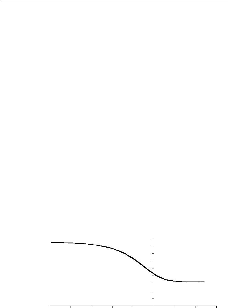
The structure is shown in Figure 16.12 in terms of the stretched coordinate
η =
(m/µ
)dx where µ
is often a strong function of temperature and thus of x.
A similar structure is obtained for all except quite small values of Pr
. In the limit
Pr
→ 0, Hayes (1958) points out that there must be a “shock within a shock” because
0
0.1
0.2
0.3
0.4
0 5
0.6
0.7
0.8
0.9
–10 –8 –6 –4 –2 0 2 4 6
U
η
U
1
= .848…
U
2
= .318…
Figure 16.12 Shock structure velocity profile for the case U
1
= 0.848485, U
2
= 0.31818, corresponding
to M
1
= 2.187.

7. Operation of Nozzles at Different Back Pressures 741
heat conduction alone cannot provide the entire structure. In fact, Becker (1922)
(footnote, p. 341) credits Prandtl for originating this idea. Cohen and Moraff (1971)
provided the structure of both the outer (heat conducting) and inner (isothermal vis-
cous) shocks. The variable η is a dimensionless length scale measured very roughly
in units of mean free paths. We see that a measure of shock thickness is of the order
of 5 mean free paths.
7. Operation of Nozzles at Different Back Pressures
Nozzles are used to accelerate a fluid stream and are employed in such systems as
wind tunnels, rocket motors, and steam turbines. A pressure drop is maintained across
it. In this section we shall examine the behavior of a nozzle as the exit pressure is
varied. It will be assumed that the fluid is supplied from a large reservoir where the
pressure is maintained at a constant value p
0
(the stagnation pressure), while the
“back pressure” p
B
in the exit chamber is varied. In the following discussion, we
need to note that the pressure p
exit
at the exit plane of the nozzle must equal the back
pressure p
B
if the flow at the exit plane is subsonic, but not if it is supersonic. This
must be true because sharp pressure changes are only allowed in a supersonic flow.
Convergent Nozzle
Consider first the case of a convergent nozzle shown in Figure 16.13, which examines
a sequence of states a through c during which the back pressure is gradually lowered.
For curve a, the flow throughout the nozzle is subsonic. As p
B
is lowered, the Mach
number increases everywhere and the mass flux through the nozzle also increases.
This continues until sonic conditions are reached at the exit, as represented by curve b.
Further lowering of the back pressure has no effect on the flow inside the nozzle. This
is because the fluid at the exit is now moving downstream at the velocity at which no
pressure changes can propagate upstream. Changes in p
B
therefore cannot propagate
upstream after sonic conditions are reached at the exit. We say that the nozzle at this
stage is choked because the mass flux cannot be increased by further lowering of
back pressure. If p
B
is lowered further (curve c in Figure 16.13), supersonic flow is
generated outside the nozzle, and the jet pressure adjusts to p
B
by means of a series
of “oblique expansion waves,” as schematically indicated by the oscillating pressure
distribution for curve c. (The concepts of oblique expansion waves and oblique shock
waves will be explained in Sections 10 and 11. It is only necessary to note here that
they are oriented at an angle to the direction of flow, and that the pressure decreases
through an oblique expansion wave and increases through an oblique shock wave.)
Convergent–Divergent Nozzle
Now consider the case of a convergent–divergent passage (Figure 16.14). Completely
subsonic flow applies to curve a.Asp
B
is lowered to p
b
, sonic condition is reached
at the throat. On further reduction of the back pressure, the flow upstream of the
throat does not respond, and the nozzle has “choked” in the sense that it is allowing
the maximum mass flow rate for the given values of p
0
and throat area. There is a