Casing/Tubing design manual october 2005 Chevron
Подождите немного. Документ загружается.


9.4.1.10 Effective Force
(
)
FF pApA
ez iioo
=− −
(9-28)
9.4.1.11 Effective Weight
(
)
ww A A
esiioo
=+ −
γγ
.(9-29)
In reviewing the calculations, note the following points. As indicated by
equation19-8, there is a possibility of a discontinuity in axial force at a cross over
between two sections because of differences in cross-sectional geometry. The
magnitude of the discontinuity will be that of the latter two pressure terms in the
equation.
Interestingly, this same discontinuity will not appear in the effective force.
Rearranging equation (9-27):
() ()() ()() () ( )
()() ()( )
FpApA F wL
pA pA
z
i
i
j
i
j
o
j
o
j
z
j
s
j
i
j
i
j
o
j
o
j
−−
⎛
⎝
⎜
⎞
⎠
⎟
=+
−−
⎛
⎝
⎜
⎞
⎠
⎟
++
++
11
11
(9-30)
The left-hand side of the above equation is the effective force just above the
section change. The right-hand side of the above equation is the effective force
just below the section change. The equality implies that these two effective
forces have the same value.
Casing/Tubing Design Manual 9-13
October 2005

9.4.2 Conditions during Stimulation
Repeating the previous calculations, the conditions during the stimulation (see
Table 9-7) can also be calculated. The equations used are identical to those
outlined above.
Table 9-7. Conditions during Stimulation
Segment Attribute Symbol Metric English
1 Axial force at bottom
F
z
96.98 kN 21,821 lb
Effective force at bottom
F
e
-58.94 kN -13,249 lb
Internal pressure at
bottom
p
i
42.71 MPa 6,195 psi
External pressure at
bottom
p
o
6.092 MPa 883.1 psi
Effective weight
w
e
13.62 kg/m 9.15 lb/ft
Average temperature
T
ave
10.70°C 51.2°F
2 Axial force at bottom
F
z
-100.0 kN -22,489 lb
Effective force at bottom
F
e
-201.9 kN -45,394 lb
Internal pressure at
bottom
p
i
63.30 MPa 9,182 psi
External pressure at
bottom
p
o
21.32 MPa 3,091 psi
Effective weight
w
e
9.56 kg/m 6.43 lb/ft
Average temperature
T
ave
13.15°C 55.6°F
3 Axial force at bottom
F
z
-128.9 kN -28,989 lb
Effective force at bottom
F
e
-230.4 kN -51,825 lb
Internal pressure at
bottom
p
i
67.42 MPa 9,779 psi
External pressure at
bottom
p
o
24.37 MPa 3,532 psi
Effective weight
w
e
9.56 kg/m 6.43 lb/ft
Average temperature
T
ave
15.25°C 59.4°F
9-14 Casing/Tubing Design Manual
October 2005

Changes in the temperature and pressure environment will attempt to induce
length changes. Since the packer here is assumed to permit motion, these length
changes will be realized. The length changes are summarized in Table 9-8,
where calculations proceed according to the following formulas.
Table 9-8. Length Changes because of Stimulation
Segment Length Change Symbol Meters Inches
1 Temperature
δ
L
te
-0.129 -5.10
Axial force
δ
L
sh
-0.079 -3.12
Ballooning
δ
L
pr
-0.171 -6.72
Buckling
δ
L
bu
-0.014 -0.50
2 Temperature
δ
L
te
-0.717 -28.32
Axial force
δ
L
sh
-0.633 -24.93
Ballooning
δ
L
pr
-0.449 -17.67
Buckling
δ
L
bu
-0.633 -24.89
3 Temperature
δ
L
te
-0.212 -8.33
Axial force
δ
L
sh
-0.127 -4.99
Ballooning
δ
L
pr
-0.097 -3.82
Buckling
δ
L
bu
-0.198 -7.82
Total for all
Segments
Temperature
δ
L
te
-1.058 -41.75
Axial force
δ
L
sh
-0.839 -33.04
Ballooning
δ
L
pr
-0.717 -28.21
Buckling
δ
L
bu
-0.845 -33.21
9.4.2.1 Temperature Change
The length change because of temperature change is,
(
)
δαδ
LLT
te ave
=
(9-31)
where for steel,
(
)
α
=
−−
12410 6910
56
././xmmCxininF
oo
, and
δ
T
ave
is the difference
in average temperatures between the initial conditions and the stimulation.
Casing/Tubing Design Manual 9-15
October 2005

9.4.2.2 Axial Force Change
The length change because of axial force changes at the shoulders must
consider the fact that, assuming the lower end of the tubing string to be free, the
effects of any axial force will be felt by all sections above the point of application
of the force. For each affected section, the change in length is given by,
δ
δ
L
FL
EA
sh
z
= (9-32)
so that for Section I:
() ()
δδ
L
L
EA
F
sh
i
i
z
j
n
=
⎛
⎝
⎜
⎞
⎠
⎟
∑
(9-33)
where, for a generic change in areas between sections,
() ()()() ()()()
δδ δ
FpAA pAA
z
j
i
j
i
j
i
j
o
j
o
j
o
j
=−
⎛
⎝
⎜
⎞
⎠
⎟
−−
⎛
⎝
⎜
⎞
⎠
⎟
++11
(9-34)
For Section 1 in this example, there will be length changes because of the axial
force at the bottom of Section 3 (i.e., the bottom of the string) and at the cross
over between Sections 1 and 2. (Although the pressure changes at the cross
over between Sections 2 and 3, there is no shoulder to absorb the change.) The
force change at the bottom of Section 3 is -128.9 - (-28.49) = -100.4 kN (-28,989
- (-6,400) = -22,589 lb). The force change at the cross over between Sections 1
and 2 is in metric units,
()
()()
δ
Fk
z
1
0001 42 71 6092 4536 3020 0 5551=− −−=... .N
b
,
and in English units,
()
()()
δ
Fl
z
1
6195 8831 7 031 4 68 0 12488=− −−=.. . .
The length change for Section 1 is in metric units,
()
()
()
δ
L
x
m
sh
1
3
609 6 1 10
206843 6207 4536
1004 5551 0079=
⋅
⋅−
⎛
⎝
⎜
⎞
⎠
⎟
−+ =−
.
.. .
,
and in English units
()
()
()
δ
L
in ft
x
in
sh
1
6
212
30 10 9 621 7 031
22589 12488 312=
⋅
⋅−
⎛
⎝
⎜
⎞
⎠
⎟
−+ =−
..
.
.
9-16 Casing/Tubing Design Manual
October 2005

9.4.2.3 Ballooning Change
(
)
(
)
δ
µ
δδ
L
E
pr pr
rr
L
pr
i
ave
io
ave
o
oi
=−
−
−
2
22
22
(9-35)
where the average pressure change is the change in average pressure over the
section.
For Section 3 in this example, the average initial internal pressure is (21.32 +
24.37) / 2 = 22.84 MPa [(3,091 + 3,532) / 2 = 3,312 psi)] and the average final
internal pressure is (63.30 + 67.42) / 2 = 65.36 MPa [(9,182 + 9,779) / 2 = 9,480
psi)]. The average internal pressure change is 65.36-22.84 = 45.52 MPa (9,480-
3,312 = 6,168 psi).
9.4.2.4 Buckling Change
Check to verify that buckling has occurred. This example is true for all sections,
that is, the effective force at the bottom of the section is negative. If not,
δ
L
bu
= 0 .
If the effective force is negative, the length change due to buckling is:
δ
L
rF
EIw
bu
ce
e
=−
22
8
(9-36)
One final correction may be necessary (in this example, for the bottom two
sections). If the neutral point is above the section, that is if
−
Fw
e
/
e
is greater
than the length of the section, the above length change must be adjusted to:
δδ
′
=−
⎛
⎝
⎜
⎞
⎠
⎟
LL
L
n
L
n
bu bu
2
(9-37)
9.4.2.5 Summary
The total length change or movement of the lower end of the tubing during the
hydraulic fracturing treatment is a shortening of 3.46 m (136.2 in.). Assuming the
tubing is “bottomed out” when it is landed; this will be the minimum length of
seals necessary to avoid unseating the tubing during the treatment.
9.5 Production Casing Design
A string of 177.8 mm (7 in.) production casing will be designed to 2,895.6 m
(9,500 ft) in a vertical wellbore using the design assumptions for a standard well.
The casing is to be run in 2,037-kg/m
3
(17-ppg) fluid and cemented with a 2,157-
kg/m
3
(18-ppg) slurry to 1,829 m (6,000 ft). The density of the completion fluid in
the tubing/casing annulus is 814.8 kg/m
3
(6.8 ppg). The previous casing string is
244.5 mm (9.625 in.) set at 1,676 m (5,500 ft).
Casing/Tubing Design Manual 9-17
October 2005

The pore pressure gradient is shown in Table 9-9.
Table 9-9. Pore Pressures for Production Casing Design Example
Depth (m)
Pore Pressure
Gradient
(kPa/m)
Depth (ft)
Pore Pressure Gradient (ppg)
426.7 10.58 1,400 9.00
1,524 15.86 5,000 13.50
1,828.8 15.98 6,000 13.60
2,133.6 16.22 7,000 13.80
2,194.6 19.62 7,200 16.70
2,438.4 17.27 8,000 14.70
The fracture gradient is shown in Table 9-10.
Table 9-10. Fracture Gradients for Production Casing Design Example
Depth (m)
Fracture
Gradient (kPa/m)
Depth (ft)
Fracture Gradient (ppg)
30.5 10.52 100 8.95
457.2 19.74 1,500 16.80
1,676.4 22.56 5,500 19.20
2,286 22.56 7,500 19.20
2,438.4 22.56 8,000 19.20
2,895.6 22.44 9,500 19.10
3,048 22.33 10,000 19.00
The pore pressure gradients and the fracture gradients are plotted in Figure 9-1.
9-18 Casing/Tubing Design Manual
October 2005
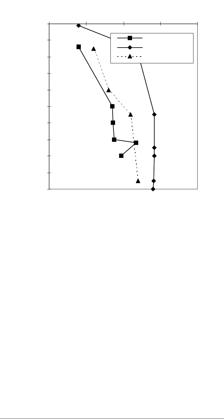
0
1000
2000
3000
4000
5000
6000
7000
8000
9000
10000
51015202
EMW (ppg)
TVD (ft)
5
Pore Pressure
Frac Gradient
Mud Weight
Figure 9-1. Pore Pressure and Fracture Gradients for Example Production Casing
Design
Casing/Tubing Design Manual 9-19
October 2005

The undisturbed surface temperature is 21.1°C (70°F), with a gradient of 2.04
°C/100 m (1.12°F/100 ft). The available inventory from which a design string may
be extracted is shown in Table 9-11Table 9-11.
Table 9-11. Tubular Inventory for Production Casing Design Example
Weight
kg/m
(lb/ft)
Grade ID
mm
(in.)
Burst
MPa
(psi)
Collapse
MPa
(psi)
Axial
Yield
kN
(klb)
Cost
Factor
34.23
(23)
K-55 161.7
(6.366)
30.06
(4,360)
22.55
(3,270)
1,628
(366)
1.00
38.69
(26)
K-55 159.4
(6.276)
34.34
(4,980)
29.85
(4,330)
1,846
(415)
1.13
38.69
(26)
N-80 159.4
(6.276)
49.92
(7,240)
37.30
(5,410)
2,687
(604)
1.42
43.16
(29)
N-80 157.1
(6.184)
56.26
(8,160)
48.47
(7,030)
3,007
(676)
1.59
43.16
(29)
P-110 157.1
(6.184)
77.36
(11,220)
58.81
(8,530)
4,132
(929)
1.85
47.62
(32)
N-80 154.8
(6.094)
62.47
(9,060)
59.29
(8,600)
3,314
(745)
1.75
47.62
(32)
P-110 154.8
(6.094)
85.91
(12,460)
74.33
(10,780)
4,559
(1,025)
2.04
9.5.1 Preliminary Design
As emphasized in Chapter 6 -Tube Load, setting the cement fixes both
extremities of the casing string
4
. Following waiting on cement (WOC),
subsequent changes in the temperature and pressure environment will induce
axial loads that are important both in their own right and as they affect collapse
and burst resistance. Unfortunately, calculation of these loads requires
knowledge of the geometry of each tube section which, at the onset of a design,
is not known. It is, therefore, necessary to perform a preliminary design to obtain
a trial design string, and then to check that design for environmental load
changes.
In the preliminary design the following working assumptions apply:
• Temperature change is ignored
• The pressure load environment is that specified with the load case definition
for the intended application (production tubing, production casing,
intermediate casing, and surface casing)
• A conservative, but not necessarily worst case, assumption is made for the
axial load
4
The lower end of the casing string is fixed by adjacent cement. The upper end of the
casing string is assumed fixed in the wellhead. The possibility of wellhead movement
will not be considered in this example.
9-20 Casing/Tubing Design Manual
October 2005

After this preliminary design is complete, the entire string geometry is defined
and a check for the effects of environmental load changes can be made. Should
any portion of the preliminary design fail the environmental load change check,
that portion of the design string can be amended and the check repeated. Note
that a repeat check is necessary, as amending the preliminary design may alter
the string geometry which, of course, alters the environmental load changes.
9.5.1.1 Collapse Design
In the preliminary design, a string is first designed that will withstand collapse
load conditions. The results of this design step are then checked for burst and
axial load resistance with amendments made, if necessary. You could
legitimately begin with the burst design and then check for collapse and axial
load.
The object of the collapse design is to arrive at the least expensive set of weight
and grade combinations that will just meet the design loads. The design starts at
the bottom because of the detrimental effect of tension on collapse. That is, to
include the effect of axial load at any depth, the weight of casing hanging below
that point must be known. As a reasonably conservative assumption, the axial
load at any depth in the preliminary design is calculated as the air weight of
casing suspended below the point of interest.
Figure 9-2 illustrates the collapse design procedure graphically. Plotting design
collapse differential pressure versus depth involves two steps:
1. Given the appropriate load case, compute the appropriate internal and
external pressure profiles. For production casing, the interior of the tube is
assumed evacuated (
p
i
=
0 ), while the exterior of the tube is subjected to
the drilling fluid in which the casing was run, in this case 2,037 kg/m
3
(17
ppg).
2. Apply the design factor for this load case to the difference of the external and
internal pressure profiles to arrive at a design collapse differential pressure.
In this particular design the collapse design factor above the cement top is
the Chevron default of 1.0, so the collapse differential pressure and the
design collapse differential pressure are identical. Below the cement top, the
collapse design factor could be 0.85 for good cement assumption, so the
design collapse differential pressure is actually less than the collapse
differential pressure as defined by the load case.
Casing/Tubing Design Manual 9-21
October 2005

0
1000
2000
3000
4000
5000
6000
7000
8000
9000
10000
0 2000 4000 6000 8000 10000
Differential Pressure (psi)
TVD (ft)
Differential Load
Load w/DF
Resistance
First Pass
29,N
26,N
26,K
23,K
32,N
Figure 9-2. Collapse Design for Production Casing Example
Starting at the bottom the least expensive weight/grade combination that will
resist a bottom hole collapse differential of 57.85 MPa (8,390 psi) is 47.62-kg/m
(32-ppf) N-80. The question then centers around how little of this weight/grade
must be used before a less expensive weight/grade combination is used. This
question is the most complicated aspect of collapse design, primarily because:
• The effect of tension on collapse
• The complex nature of the API adjustment of collapse resistance for axial
load.
To illustrate this point, consider the following thoughts:
• The next least expensive weight/grade combination is 43.16-kg/m (29-ppf) N-
80.
• The collapse resistance of this candidate is 48.47 MPa (7,030 psi) which,
when compared to the design collapse differential pressure corresponds to a
depth of 2,773 m (9,100 ft).
• If, however, such a candidate were run to this depth, its collapse resistance
would actually be 48.13 MPa (6,980 psi). This reduction is because of the
weight of 47.62- kg/m (32-ppf) N-80 casing suspended below the 43.16-kg/m
(29-ppf) N-80.
9-22 Casing/Tubing Design Manual
October 2005