Casing/Tubing design manual october 2005 Chevron
Подождите немного. Документ загружается.

generating excess axial tensile forces at the top of intermediate or production
casing also increases. One common means of reducing axial tension is to run a
casing string as two separate sections. The lower section is referred to as a
“liner.” Liners are partial casing strings that are hung from the preceding casing
string and usually cemented along their entire length. The upper portion of the
composite assembly, commonly referred to as a “tieback,” may or may not be
installed according to the particular application.
In addition to reducing the maximum tension in a casing string, a liner also has
obvious economic benefits. The primary disadvantage of a liner, however, is the
increased possibility of a leak in the overall system associated with the practical
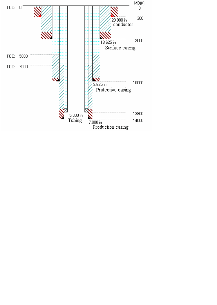
difficulties of obtaining a competent cement seal at the liner top. See Figure 1-2
for a example well scheme.
Figure 1-2. Example Well Scheme
1.4 Production Tubing
The innermost tubular string in a well design is termed the “tubing string.” Except
in cases of completions involving annular flow, the primary purpose of the tubing
string is to serve as a conduit for produced reservoir fluids. A related function of
the tubing string is to serve as a receptacle and/or delivery system for various
pumps, valves, and other tools placed downhole to enhance the recovery of
reservoir fluids. This latter function, coupled with the fact that the tubing string is
in direct contact with corrosive fluids or possible erosive fluids/solid mixtures,
normally dictates that the tubing string be readily recoverable. For this reason,
the tubing/production casing annulus is usually temporarily sealed with a packer
rather than permanently sealed with cement.
The tubular program for a well is typically sized from the inside outward starting
with the tubing string. A tubing string properly sized for optimum production of
reservoir fluids should quickly compensate for any extra drilling or casing
expenditures necessary to accommodate that tubing diameter.
Casing/Tubing Design Manual 1-5
October 2005

1.5 Tubular Combinations
A tubular string consists of a number of shorter length segments commonly
referred to as “joints.” A generic joint of given outside diameter may be identified
by three parameters:
1. The nominal weight per foot or, equivalently, the tube wall thickness.
2. The grade of steel of which the joint is composed. (Tubular grades are
commonly designated by a letter prefix and a number. The letter prefix is
usually historical and of no practical value. The number appearing in the
grade designation represents the minimum yield strength of the casing steel
in thousands of psi.)
3. The type of threaded connection at either end of the joint.
Appendix A shows a typical inventory of weight/grade/thread combinations.
When you include the API-designated tubulars and the various proprietary
weights, grades, and/or threads, the number of combinations can be staggering.
For the more popular sizes, such as 177.8 mm (7 in.) or 244.48 mm (9-5/8 in.)
casing, the number of combinations can be as high as 2,400. Nevertheless, as
mentioned in subsequent discussions, a large amount of culling can be
performed before considering a collection of weight/grade/thread combinations in
a particular design.
1.6 Anticipated Loads
The loads to which tubulars can be subjected are myriad, but can ultimately be
divided into the following three categories:
1. Differential pressure loads on the cross section
2. Axial loads on the casing body and connection
3. Bending loads
The discussion in this section is primarily intended to provide a general overview
of the origins of casing loads. More detailed discussions of each load type can be
found in subsequent text.
Cross-sectional loading invariably results either directly from subsurface
formation pressures or indirectly from attempts to control these pressures.
Normal pressures are a result of the hydrostatic gradient of pore fluids (usually
salt water), which is transmitted by vertical communication between pore spaces.
However, in some instances, extremely low permeability boundaries surrounding
a formation can result in subsurface pressure anomalies. These abnormal
pressure zones cause a large number of casing problems. The difficulty with
abnormal pressure zones is due to these factors:
• The magnitude of the pressure acting external to casing opposite the zone
• The possibility that escape of formation fluids, specifically gases, into the
wellbore can result in large internal pressures (see gas kick pressure in
Figure 1-3) on previously run, shallower casing.
1-6 Casing/Tubing Design Manual
October 2005
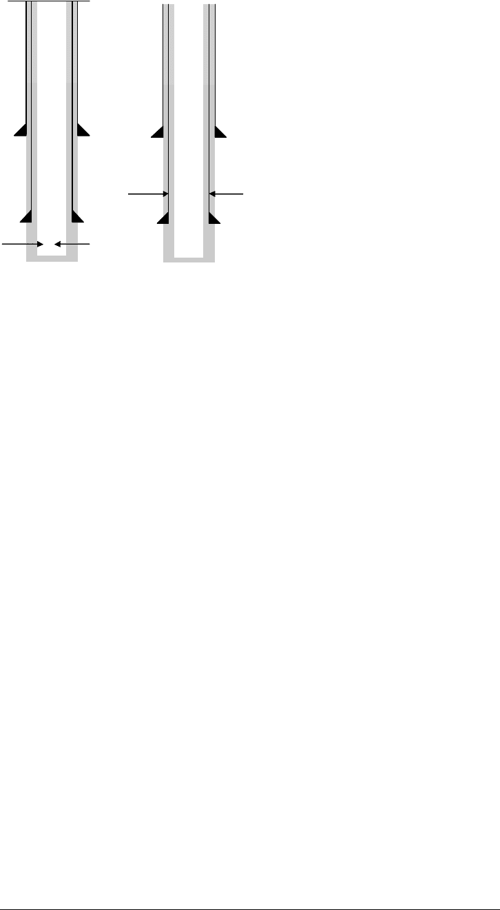
Burst Load:
Gas kick pressure
p
i
Collapse Load:
Mud pressure
Figure 1-3. Illustration of Example Casing Burst and Collapse Loads
Aside from abnormal pressure zones, most other casing pressure loadings are a
result of mechanical failures. For example, a tubing leak at the surface can result
in the imposition of (essentially) reservoir pressure at the surface of the
production casing string. This surface pressure, coupled with the hydrostatic
head of the completion fluid in the tubing/casing annulus can impose substantial
internal pressures on the casing (and, conversely, external pressure on the
tubing). On the other hand, later in the life of the well when the reservoir pressure
has declined, a packer leak at the lower end of the tubing will result in a decrease
in the hydrostatic pressure internal to the casing, or, equivalently, an increase in
differential external pressure.
With respect to pressure loads, it is worth mentioning that almost every
conceivable pressure loading has been known to occur in actual field situations.
It is important that nothing be taken for granted during the design process. For
example, (and to reinforce a point made earlier concerning the importance of the
cement sheath as a pressure isolation “tool”), it is possible to induce production
casing collapse during a high-pressure hydraulic fracturing stimulation if the
cement sheath is either inadequate (i.e., channeling, casing not properly
centralized) or inadvertently cracked during stimulation. Although these scenarios
may seem only remotely possible, the importance of the well and/or the
consequences of a failure may dictate that such occurrences be anticipated in
the design.
Axial loads on tubulars are unavoidable. At the very least, a generic joint will be
subjected to an axial load because of the weight of tubulars suspended below it
plus any end load acting at the bottom of the string. However, throughout the life
of a well additional loads may be generated in various portions of the string
because of changes in the conditions under which the tubular was initially
installed.
Casing/Tubing Design Manual 1-7
October 2005

Incremental axial loads, loads generated after initial installation, can be divided
into two classes according to their origin. The first class includes those loads
directly resulting from completion procedures. Included here are the increment in
tension/compression in an unsupported interval due to landing practices
(pull/slackoff) and, possibly, discrete loads imposed at a given point in a string
because of hanging a smaller string of tubulars. Such imposed loads obviously
affect string tension and are invariably taken into consideration in design
calculations.
The second class of incremental axial loads, specifically those loads resulting
from environmental changes, is by far the more dangerous in terms of their
potential to cause casing failure, primarily because such effects may be ignored
during the design process. Countless unnecessary tubular failures can be
attributed to the combined effects of incremental tensions resulting from:
• Temperature change—An increase/decrease in temperature will attempt to
lengthen/shorten a tubular string. However, if the tube is fixed between any
two points in the wellbore, a corresponding axial compression/tension is
induced.
• Pressure change—The effect of internal and/or pressure change is twofold:
o First, hydrostatic pressure acts on exposed shoulders associated
with changes in either the inside or outside diameter of the tube.
Changes in hydrostatic pressure will, therefore, be accompanied by
changes in the magnitude of these shoulder forces.
o Second, radial expansion/contraction of a tube cross section
because of pressure changes will be accompanied by a longitudinal
contraction/expansion (i.e., Poisson’s effect). However, if any portion
of the tubular string is fixed in such a manner as to prevent axial
movement, a longitudinal tension/compression will be induced
3
.
Bending loads have been listed as a separate effect due to the fact that bending,
although always present, is often of such magnitude that its effects may be
ignored. However, when wellbore curvatures become sufficiently large to require
that bending effects be considered, the analysis can become quite complex. This
is particularly true when one attempts to analyze the portion of a joint most
susceptible to bending effects, the threaded connection.
Bending may also appear as a result of column buckling. Usually, the effects of
column buckling are more pronounced in tubing than in casing because of larger
associated radial clearances.
1.7 Failure Modes
Casing failure modes are usually segregated into the following topics:
• Burst
• Collapse
3
This latter increment force is often termed ballooning.
1-8 Casing/Tubing Design Manual
October 2005
• Tension/compression
• Triaxial yield
• Joint integrity
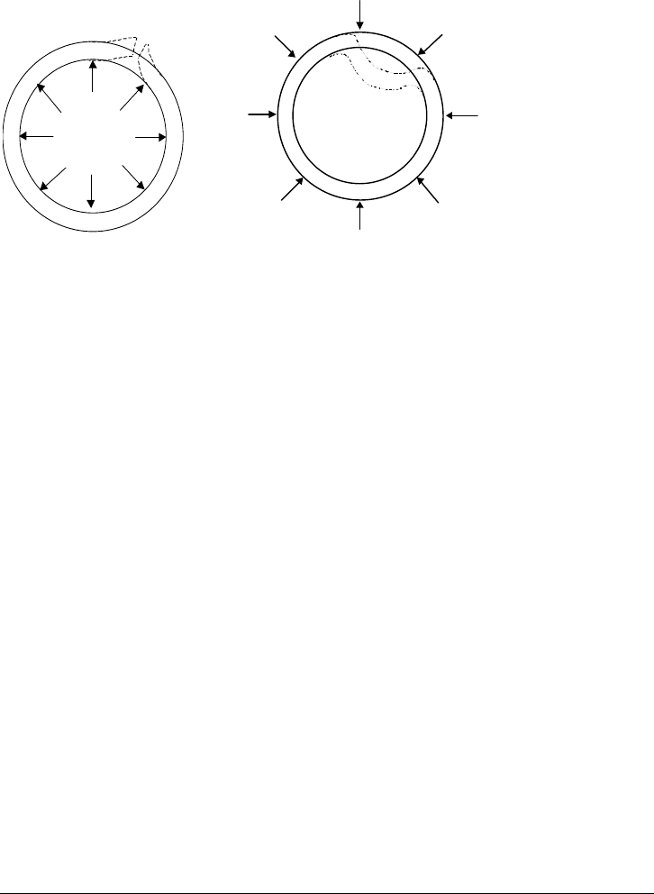
The term “burst” is applied to those failures resulting primarily from excess
internal pressure differential as shown in Figure 1-4. Conversely, the term
“collapse” is describes those failures of the tube body resulting primarily from
excess external pressure differential (see Figure 1-4). The term
“tension/compression” is applied to those failures resulting from excess axial
tension or compression. Additionally, as casing in the well is under a three-
dimensional stress condition, casing may fail in accordance with a
multi-dimensional criterion (yielding) that requires that all stresses acting at a
given point be considered simultaneously.
Internal
Pressure
Differential
Burst
External
Pressure
Collapse
External
Pressure
Differential
Figure 1-4. Tube Burst and Collapse Failures
The integrity of casing connections may be subdivided into two subjects–leak
integrity and strength integrity. The leak integrity of a connection has to do with
the ability of a connection to contain (primarily internal) pressure. Leak integrity is
primarily concerned with determining the pressure conditions necessary to
negate the bearing pressure existing between mating surfaces as a result of
initial assembly of the connection.
The strength integrity of threaded connections is the least understood failure
mode. Although semi-empirically derived predictions of joint strength integrity
provide adequate estimates of connection performance in most instances, by far
the largest number of unexplained casing failures can be traced to inadequate
connection strength (usually termed “joint strength”). These failures can often be
attributed to a lack of knowledge concerning the performance of threaded
connections under non-axial, non-static loads, such as those associated with
bending, wellbore pressure surges, and dynamic loads induced during running.
Additional failure modes of non-mechanical origin, such as corrosion and sulfide
stress cracking, are also of paramount concern to the design engineer. Coverage
of these topics here is limited to those aspects that directly affect the stress-strain
response of the tubular to its mechanical environment.
Casing/Tubing Design Manual 1-9
October 2005

1-10 Casing/Tubing Design Manual
October 2005
1.8 Organization of Text
The remainder of this manual presents summary recommendations and
guidelines to use in routine tubular design applications, including knowledge of
tubular performance (Figure 1-5) and tubular loads (Figure 1-6). This information
is supplemented by a number of appendices providing supporting derivations of
the equations presented in the text. The remaining chapters and appendices in
this manual are described in the following list.
Chapter 2 Discusses casing setting depth and sizing for well construction
Chapter 3 Focuses on the tube materials, discussing tube specification
(API/ISO), temperature effect, and sour service
Chapter 4 Continues a discussion of tube performance (resistance) and
presents tube specifications (API/ISO) on burst, collapse,
tension/compression, and triaxial strength
Chapter 5 Provides information pertaining to tube connection and
connection selection based on well conditions
Chapter 6 Discusses the defining of tube loads used in designing a tubular
Chapter 7 Details the important, but controversial, subject of column
buckling. This discussion of tube buckling is from a
phenomenological viewpoint, and presents illustrative
calculations.
Chapter 8 Defines the tube design approach along with the previous
chapters
Chapter 9 Reinforces the information in chapter 8 and provides a number of
example designs
Chapters 10
through 13
Presents more design discussions on steam injection casing
design, deepwater casing design, probabilistic casing design, and
tubing performance/design
Appendix A Discusses casing/tubing spreadsheet design as a first- pass
design approach
Appendix B Presents the casing design software “StressCheck
®”
Appendix C Introduces WellCAT
®
tubing design software
Appendix D
Contains detailed derivations of equations used in the main body
of the text.
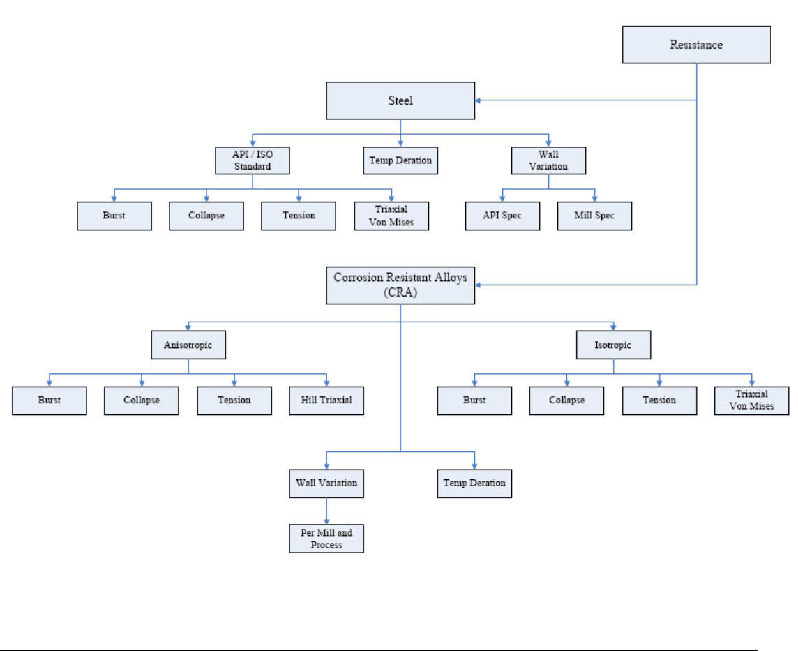
Figure 1-5. Tube Performance (Resistance) Flowchart
Casing/Tubing Design Manual 1-11
October 2005
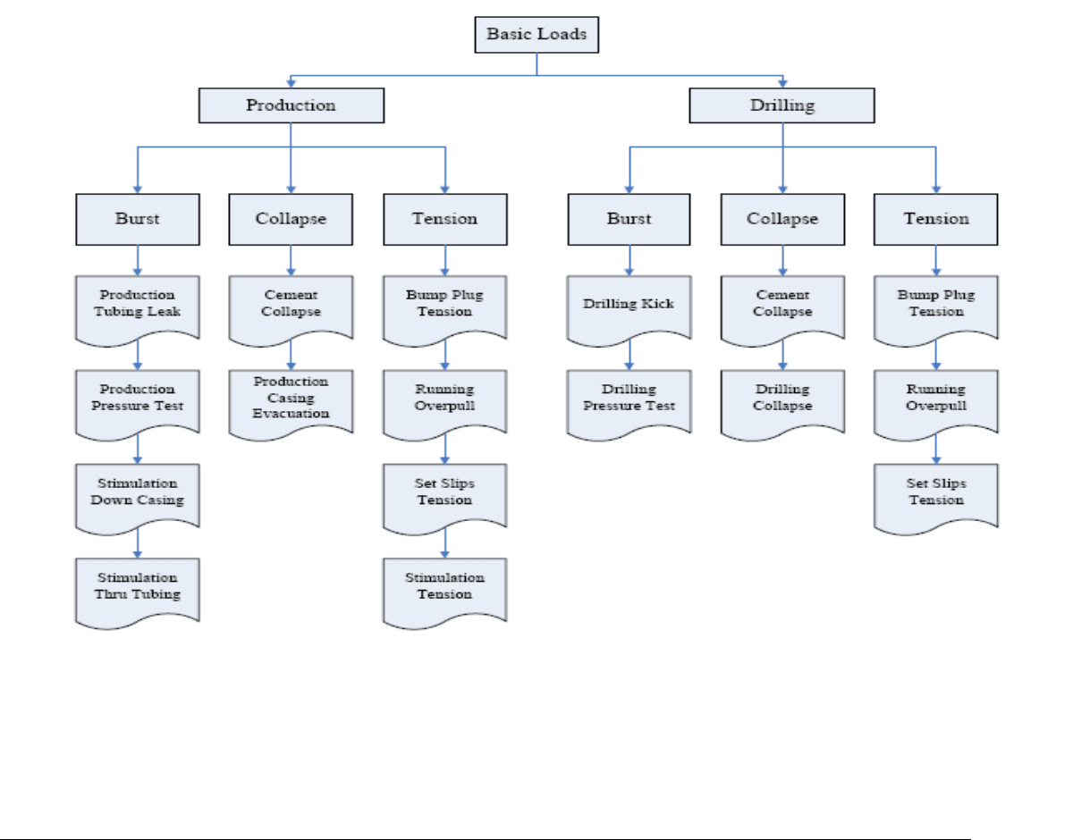
Figure 1-6. Tube Load Flowchart
1-12 Casing/Tubing Design Manual
October 2005

1.9 References
1. Bailey, L. et al.: “Drilling Fluid and Wellbore Stability-Current Performance
and Future Challenges,” Chemicals in the Oil Industry, ed. by P. H. Ogden.
Royal Society of Chemistry, London, 1991.
2. Chenevert, M. E.: “Shale Alteration by Water Absorption,” JPT (September
1970), 1141-1148
3. Colback, P. S. B. and Wiid, B. L.:”The Influence of Moisture Content on the
Compressive Strength of Rocks,” Proceedings of the Rock Mechanics
Symposium, 3rd Canadian Symposium, Toronto, Canada, 1965, 65-83.
4. Mody, F. K. and Hale, A. H.: “Borehole-Stability Model to Couple the
Mechanics and Chemistry of Drilling Fluid/Shale Interactions,” paper
IADC/SPE 25728 presented at the 1993 SPE/IADC Drilling Conference,
Amsterdam, Netherlands, February.
Casing/Tubing Design Manual 1-13
October 2005

2
2 Tube Setting Depth and Size
2.1 Introduction ......................................................................................................................2-1
2.2 Casing Setting Depths......................................................................................................2-1
2.2.1 Outline of Procedure....................................................................................................2-3
2.2.2 Adjustments to the Procedure .....................................................................................2-3
2.2.2.1 Differential Sticking.................................................................................................2-4
2.2.2.2 Formation Constitution............................................................................................2-4
2.2.2.3 Government Regulations........................................................................................2-4
2.2.2.4 Conductor Casing...................................................................................................2-4
2.2.3 Example Problem........................................................................................................2-4
2.2.3.1 Pore Pressure Gradients........................................................................................2-5
2.2.3.2 Fracture Gradients..................................................................................................2-5
2.2.3.3 Step 1–Plot Upper and Lower Drilling Fluid Limits with Margins.............................2-6
2.2.3.4 Step 2–Determine Initial Requirements for Wellbore Integrity ................................2-7
2.2.3.5 Step 3–Check for the Possibility of Differential Sticking..........................................2-8
2.2.3.6 Step 4–Check Formation Constitution....................................................................2-9
2.2.4 Final Results..............................................................................................................2-10
2.2.5 Sizing Tubulars for a Wellbore ..................................................................................2-11
2.2.6 Example Problem......................................................................................................2-13
2.3 References.....................................................................................................................2-14
2.1 Introduction
This section details the engineering design fundamentals for determining setting
depths of different casing strings in the wellbore/formation environment. Casing
sizing is another issue. We have to continuously reduce the size of the casing
strings one by one while drilling the well deeper, in order to set the production
casing or liner to the planned target depth.
2.2 Casing Setting Depths
As mentioned in the 1 - Overview, casing is run to compensate for inadequacies
of the rock comprising the wellbore wall. Casing may be needed to counter any
or all of the factors related to rock permeability, rock relative weakness, and
chemical activity. Typically, however, casing setting depths are related to
wellbore fluid influx and formation strength. The objective of optimizing casing
setting depths is to arrive at a suite of drilling fluid weights necessary to provide
trouble-free drilling throughout the well.
Casing/Tubing Design Manual 2-1
October 2005