Burton T. (et. al.) Wind energy Handbook
Подождите немного. Документ загружается.

difficult and expensive to undertake as they involv e taking the wind farm out of
commission and arranging a temporary earth at the remote end of the current
injection circuit. Also it is becoming increasingly difficult to use a telephone circuit
to provide the remote earth reference as telecommunication companies increasingly
use non-metallic media. However, it is very questionable whether simpler tests give
useful results on large earthing networks with significant series inductance.
10.3 Lightning Protection
It is now recognized that lightning is a significant potential hazard to wind turbines
and that appropriate protection measures need to be taken. Some years ago, it was
thought that as the blades of wind turbines are made from non-conducting material
(i.e., glass reinforced plastic (GRP) or wood-epoxy) then it was not necessary to
provide explicit protection for these types of blades provided they did not include
metallic elements for the operation of devices such as tip brake s. However, there is
now a large body of site experience to show that lightning will attach to blades
made from these materials and can cause catastrophic damage if suitable protection
systems have not been fitted. Of course, if carbon fibre (which is conducting) is used
to reinforce blades then additional precautions are necessary. In response to
damage experienced on sites a number of new standards and recommendations for
the lightning protection of wind turbines have been developed (Cotton et al., 2000,
International Energy Agency, 1997, IEC, 2000a).
Lightning is a complex natural phenomenon often consisting of a series of
discharges of current. The term ‘lightning flash’ is used to describ e the sequence of
discharges which use the same ionized path and may last up to 1 s. The individual
components of a flash are called ‘strokes’.
Lightning flashes are usually divided into four main categories:
• downward inception, negative and positive polarity, and
• upward inception, negative and positive and polarity.
Generally flashes which start with a stepped leader from the thunder cloud and
transfer negative charge to earth (downward inception – negative polarity) are the
most common. Downward negative flashes typically consist of a high-amplitude
burst of current lasting for a few microseconds followed by continuing current of
several hundred amps. Then, following the extinction of the initial current transfer
between cloud and earth there may be a number of restrikes. However, in some
coastal areas there may be a majority of positive flashes of downward inception
which consist of a single long duration strike with high charge transfer and specific
energy content. Upward ince ption is normally associated with very high objects
(e.g., communication towers) and the lightning has very different characteristics.
Although the maximum peak current of this form of lightning is low (some 15 kA)
the charge transfer can be very high and hence has significant potential for damage.
The top of wind turbine blades can now be over 100 m above ground and so there
LIGHTNING PROTECTION 565

is growing concern over the effect of upward negative lightning flashes. Upward
positive flashes are rare.
Table 10.2 shows the parameters normally used to characterize lightning and
some aspects of their potential for damage in wind turbines. The peak current of a
single lightning stroke is over 200 kA but the me dian value is only approximately
30 kA. Corresponding values for charge transfer are 400 C (peak), 5 C (median) and
specific energy 20 MJ= (peak) and 55 kJ= (median). The very large range of these
parameters implies that the initial step in any consideration of lightning protection
of a wind farm or wind turbine is to undertake a risk assessment (IEC, 2000a). The
risk assessment will include consideration of the location of the turbines as the
frequency and intensity of lightning varies considerably with geography and
topology.
Table 10.3 shows some historical data of the frequency of lightning damage
(Cotton et al., 2000). Although this must be interpreted with care, as both wind-
turbine design and lightning-protection systems were evolving rapidly during this
period, the data do indicate the scale of the problem. A large number of the faults
shown in Table 10.3 were due to indirect strokes effecting the wind turbine and
wind farm control systems. Generally the number of faults was dominated by those
to the control and electrical systems while blade damage gave the highest repair
costs and loss of turbine availability, and hence reduction in wind farm revenue.
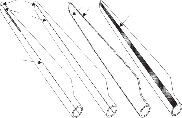
Figure 10.5 shows the techniques commonly used to protect blades against
lightning. The main distinction is whether a limited number of receptors are used to
intercept the lightning (Types A and B) or if an attempt is made to protect the entire
blade (Types C and D). Type A shows how, using one or two receptors at the tip,
the steel control wire of the tip brake may be used as the down conductor. In a
blade without a moveable tip (Type B) then an additional conductor is installed.
Type C has the down co nductor located on the leading and trailing edges although
there are considerable practical difficulties in firmly attaching a suitable conducting
path to the leading edge. Type D shows the use of a conducting mesh on each side
Table 10.2 Effects of Various Aspects of Lighting on a Wind Turbine
Parameter Effect on wind turbine
Peak current (A) Heating of conductors, shock effects,
electromagnetic forces
Specific Energy (J=) Heating of conductors, shock effects
Rate of rise of current (A/s) Induced voltages on wiring, flashovers, shock effects
Long duration charge transfer (C) Damage at arc attachments point or other arc sites
(e.g., bearing damage)
Table 10.3 Wind-Turbine Lightning Damage Frequency (Cotton et al., 2000)
Country Period Turbine years Lightning faults Faults per 100 turbine years
Germany 1991 to 1998 9204 738 8.0
Denmark 1991 to 1998 22 000 851 3.9
Sweden 1992 to 1998 1487 86 5.8
566
ELECTRICAL SYSTEMS
of the blade. The main mechanism of damage is when the lightning current forms
an arc in air inside the blade. The pressure shock wave caused by the arc may
explode the blade or, less dramatically, cause cracks in the blade structure. Thus,
for effective protection it is essential that the lightning attaches directly to the
protection system and then is conducted safely down the length of the blade in a
metallic conductor of adequate cross section.
Service experience would seem to indicate that the use of a tip receptor works
effectively for blades of up to 20 m in length. There are limited data available for
very large wind turbines but it would appear to be questionable if a receptor only at
the tip will give good protection for very long blades.
Once the lightning current has been conducted to the root of the blade there
remains the problem of ensuring its safe passage to the outside of the tower and
hence to earth. This is not straightforward as it is necessary for the current to pass
across the pitch, shaft and yaw bearings while not damaging the generator and
sensitive control equipment in the nacelle. The present understanding of how
wind-turbine bearings may be damaged by the passage of lightning current is
summarized in IEC (2000a). Generally large, heavily loaded, bearings are unlikely
to be catastrophically damaged although there may be a reduction in their service
life. There is, so far, no effective means of shunting lightning current around a large
bearing as the bearing itself is the lowest inductance path and so the preferred route
for the high- frequency current.
The control and electrical systems are protected against lightning by dividing the
turbine into zones depending on whether direct attachment of lightning is possible
and the magnitude of the current and hence electromagnetic field expected in each
Type A Type B Type C Type D
Receptor
Down
conductor
Steel wire
Down
conductor
Metal mesh
Figure 10.5 Blade Lightning-protection Methods (Reproduced from Cotton et al., 2000, by
Permission of Dr R. Sorenson, DEFU)
LIGHTNING PROTECTION 567
zone (IEC, 2000a). Within each zone components are pro tected to withstand the
anticipated effects of lightning. The principal damage mechanisms to electrical and
control systems are direct conduction and magnetic coupling while the main
protective measures are good bonding, effective shielding and the use of appro-
priate surge protection devices at the zone boundaries.
10.4 Embedded (Dispersed) Wind Generation
The wind is a diffuse source of energy with wind farms and individual turbines
often distributed over wide geographical areas, and so the public electricity
distribution networks, whic h were originally constructed to supply customer loads,
are usually used to collect the electrical energy. Thus wind generation is said to be
embedded in the distribution network or the generation is described as being
dispersed. The terms embedded generation and dispersed generation can be consid-
ered to be synonymous. Conventional distribution systems were designed for a
unidirectional flow of power from the high-voltage transmission network to the
customers. Significant generation was not considered in the initial design of the
distribution network s and alters the way they operate. Connection of embedded
generation to distribution networks has important consequences both for the wind-
farm developer and the operator of the distribution network and is the subject of
continuing interest (CIRED, 1999, CIGRE, 1998, Jenkins, 1995, 1996).
10.4.1 The electric power system
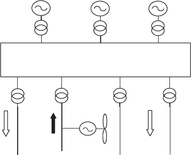
Figure 1 0.6 is a diagrammatic representation of a typical modern electric power
system. The electrical power is generated by large ce ntral generating sets and is
then fed into an interconnect ed high-voltage transmission system. The generating
units may be fossil-fuel, nuclear or hydro sets and will have capacities of up to
Interconnected
transmission network
e.g. 400 kV
Central
generators
Generator
transformers
Bulk supply
transformers
Distribution
network
LoadsLoads
Figure 10.6 A Typical Large Utility Power System
568
ELECTRICAL SYSTEMS
1000 MW. The generation voltage is rather low (typically around 20 kV) to reduce
the insulation requirements of the machine windings and so each gene rator has its
own transformer to increase the voltage to that of the transmission syst em. The
transmission network is interconnected, or meshed, and so there can be many paths
for the electrical power to flow from the gen erator to the bulk supply transformers.
The bulk supply transformers are used to extract power from the transmi ssion
network and to provide it to the distribution networks at lower voltages. Practice
varies from country to country but primary distribution voltages can be as high as
150 kV. Distribution networks are normally operated radially with a single path
between the bulk supply transformers and the loads. In urban areas with high loads
the distribution networks use large cables and transformers and so have a high
capacity. However, in rural areas the customer load is often small and so the
distribution circuits may have only a limited capability to transport power while
maintaining the voltage within the required limits. Most wind farms are connected
to rural, overhead distribution lines. The design of these circuits tends to be limited
by consideration of voltage drop rather than thermal constraints and this severely
limits their ability to accept wind generation.
10.4.2 Embedded generation
In the early days of electricity supply, each town or city had its ow n generating
station supplying the local load. Thus all generation was local and embedded into
the distribution ne tworks. This arrangement suffered from two major problems: (1)
the generating sets were rather small and hence of low efficiency, and (2) each
station had to keep an additional generator running in case of breakdowns. Then in
the 1930s it was found to be techni cally possib le and cost-effective to interconnect
these individual power stations so that larger, more efficient generating sets could
be used and the requirement for reserve generation could be reduced. Over time,
the size and voltage of the interconnected grid networks increased and so now
voltages of 400 kV and even 765 kV are common and a single grid connects most of
continental western Europe. There have also been significant advances in the
technologies of central generating plant and, for example, large modern combined
cycle gas turbine (CCGT) generating units have efficiencies approaching 60 percent.
However, over the last 10 years there has been a resurgence in interest in
embedded generation stimulated by the need to reduce gaseous emissions from
generating plant. Three major themes may be iden tified: (1) increased development
of combined heat and power (CHP), (2) exploitation of diffuse renewable energy
sources, and (3) deregulation of the electricity supply industry and the separation
of generation and supply of energy from the operation of transmission and
distribution networks.
CHP plants operate at very high overall thermal efficiencies and so reduce the
total fossil-fuel co nsumed and hence the gaseous emissions. In addition to the
existing commercially available technologies there are major development efforts in
very small CHP generators for domestic use and also in the application of fuel cells.
Primary distribution circuits can accept power injections of up to 100 MW and so
most on-shore wind generation is likely to be embedded in a distribution system.
EMBEDDED (DISPERSED) WIND GENERATION 569
There is also considerable interest in much smaller-scale renewable energy schemes,
e.g., individual wind turbines or dispersed wind farms.
Finally, since the mid-1990s many countries have deregulated their electricity
supply systems and separated the production and sale of electrical energy from the
ownership and operation of the transmission and distribution networks. This has
opened new commercial opportunitie s for embedded generation as access to the
distribution network has become easier to obtain and the various costs and benefits
of the electricity supply system have become more transparent.
10.4.3 Electrical distri bution networks
The conventional function of an electrical distribution network is to transport
electrical energy from a transmission syst em to customers’ loads. This is to be done
with minimal electrical losses and with the quality of the electrical power main-
tained. The voltage drop is directly proportional to the current while the series loss
in an electrical circuit is proportional to the square of the current. Therefore the
currents must be kept low which, for constant power transmitted, implies that the
network voltage level must be high. However, high-voltage plant (e.g., lines, cables
and transformers) are expensive due to the cost of insulation and so the selection of
appropriate distri bution network voltage levels is an economic choice.
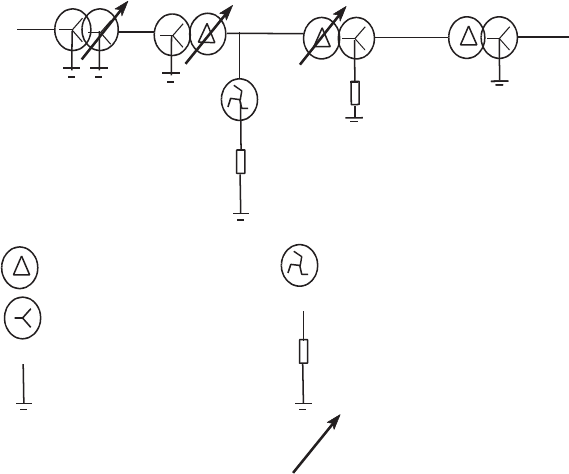
Figure 10.7 is a schematic representation of a typical UK distribution system
although most countries will have similar networks. Power is extracted from the
400 kV
or 275 kV
132 kV 33 kV 11 kV 400V
Delta-connection transformer winding
Star-connection transformer winding
Neutral point connection to earth
Earthing transformer, interconnected star winding
Neutral point connection to earth through an impedance
On load tap changer
Figure 10.7 Typical UK Distribution Voltage Transformation and Earthing Arrangements
570
ELECTRICAL SYSTEMS
interconnected transmission grid and then transformed down to the primary
distribution voltage (132 kV in this case). The electr ical energy is then transported
via a series of underground-cable and overhead-line circuits to the customers. Mos t
customers typically receive electrical energy at 400 V (for a three-phase connection)
or 230 V (for a single-phase connection). As the power required to be transmitted in
a distribution circuit reduces the circuit volta ge level is lowered by transformers.
The majority of distribution circuits are three phas e although in some rural areas
single-phase circuits are used. Only balanced three-phase netw orks are suitable for
the connection of large wind generators. Three-phase transformer windings may be
connected either in star or in delta and the winding arrangement chosen varies
from region to region and generally follows historical practice. One advantage of
the star connection is that the system neutral point is directly accessible and so can
easily be grounded or earthed. Where a delta winding connection is used an
accessible star point may be created by an earthing transformer. UK practice is to
earth the neutral points of each voltage level at one point only, although in some
continental European countries distribution networks are operated with the neutral
point isolated.
Current passing through a circuit leads to a change in voltage and this is
compensated for by altering the ratio (or taps) of the transformers. 11 kV=400 V
transformers have fixed taps which can only be changed manually when no current
flows. However, higher-voltage transformers have on-load tap changers that can be
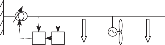
operated automatically when load current is passing. The simplest control strategy
is to use an automatic voltage controller (AVC) to maintain the lower voltage
terminals of the transformer close to a set-point (Figure 10.8). The AVC operates by
measuring the voltage on the busbar, comparing it with a set-point value and then
issuing an instruction to the on-load tap changer to alter the ratio of the transformer.
Control systems of this type are unaffected by the presence of wind generators on
the network. Even if the power flow through the transformer is reversed and power
flows from the lower-voltage to the higher-vo ltage network, the control system will
work satisfactorily. This is because the network source impedance is much less than
the equivalent impedance of the wind generators and so the network voltage is
controlled predominantly by the tap changer. Some designs of tap changer have a
reduced current rating if power flows from the low-voltage side to the high-voltage
side of the transformer. However, it is rare for embedded wind generation to
require the full reverse power flow capacity of a transformer on the distribution
network.
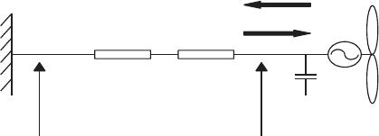
AVC LDC
Load Load
VI
Figure 10.8 Voltage Control of a Distribution Circuit (after Lakervi and Holmes, 1995); AVC
- Automatic Voltage Control, LDC - Line Drop Compensation
EMBEDDED (DISPERSED) WIND GENERATION 571

In some distribution networks, more sophisticated control techniques are used to
control the voltage at a remote point along the circuit (Lakervi and Holmes, 1995).
This is a chieved by adding to the local voltage input a signal proportional to the
voltage drop on the network. This is referred to as line-drop compensation (LDC). The
LDC elemen t measures the current flowing in the circuit and applies this to a
simple model of the distribution circuit (i.e., the resistance and inductance to the
point at which the voltage is to be controlled). The resulting voltage is then
subtracted from the local voltage measu rement. In practice, if wind generators are
connected to the network then the current flow in the circuit will be changed, the
effective impedance to the point at which the voltage is to be controlled will alter,
and so the LDC technique will no longer work correctly. LDC is sometimes known
as positive-reactance compounding and a further technique, negative-reactance
compounding, may also not function correctly with embedded generation con-
nected to the circuits. Further discussion of the effect of embedded generation on
transformer voltage controllers is given by Thomson (2000).
The voltage change permitted in 11 kV circuits is small (typically þ/1 percent
or 2 percent) as any voltage variation is passed directly through the fixed tap
transformers to the customers’ supply. In contrast, 33 kV and 132 kV circuits are
allowed to operate over a wider voltage range (up to þ/6 perce nt) as the
automatic on-load tap changes can compensate for variations in network voltage.
Hence, it is common to find that only very limited capacities of wind generation can
be connected at 11 kV as the high impedance of the circuits and relatively large
currents flowing from the generators result in unacceptable variations in voltage.
Determining the size of a wind farm which may be connected to a particular point
in the distribution network requires a series of calculations based on the specific
project data. However, Table 10.4 gives some indication of the maximum capacities
which experience has indicated may be connected. Table 10.4 assumes that the
wind farms are made up of a number of turbines and so the connection assessment
is driven by voltage rise effects and not by power qua lity issues due to individual
large machines.
The electrical ‘strength’ of a circuit is described by its short-circuit or fault level.
The short-circuit level is the product of the pre-fault voltage and the current which
would flow if a three-phase symmetrical fault were to occur. Clearly, this combina-
tion of current and voltage cannot occur simultaneously but the fault level (ex-
pressed in MVA) is a useful parameter which gives an immediate understanding of
the capacity of the circuit to deliver fault current and resist voltage variations. In
Table 10.4 Indication of Possible Connection of Wind Farms
Location of connection Maximum capacity of wind farm
(MW)
Out on 11 kV network 1–2
At 11 kV busbars 8–10
Out on 33 kV network 12–15
At 33 kV busbar 25–30
On 132 kV network 30–60
572
ELECTRICAL SYSTEMS

the ‘per-unit system’ the fault level is merely the inverse of the magnitude of the
source impedance (Weedy and Cory, 1998).
10.4.4 The per-unit system
The per-unit system is simply a technique used by electrical power engineers to
simplify calcul ation by expressing all values as a ratio:
actual value (in any unit)
base or reference value (in the same unit)
Its advantages include: (1) a reduction in the appearance of
ffiffiffi
3
p
in the calculations,
(2) that similar per-unit values apply to systems of various sizes, and (3) by careful
choice of voltage bases the solution of networks containing several transformers is
facilitated.
For simple calculations, such as the those required for assessment of wind farms
on simple distribution circuits, all that is required is for these steps to be followed.
(1) Assume an arbitrary base VA (e.g., 10 MVA)
(2) Select voltage bases of each voltage level of the network (e.g., 33 kV and 11 kV).
These voltage bases should be related by the nominal turns ratios of the
transformers.
(3) Calculate the appropriate real and reactive power flows at the generator
terminals as a per-unit value (i.e., for a power flow of 5 MW with the base VA
chosen as 10 MVA, the per-unit value is P ¼ 5=10 or 0.5 per unit, and similarly
for a reactive power flow of 1 MVAr the per-unit value is Q ¼ 1= 10 or 0.1 per
unit).
(4) If necessary, transform the impedances of the circuit from ohmic to per-unit
values using a base impedance of Z
base
¼ V
2
base
=VA
base
.
(5) The base current at any particular voltage level may be calculated from:
I
base
¼ VA
base
ffiffiffi
3
p
3 V
base
.
The per-unit system is used in Example 10.1.
10.4.5 Power flows, slow-voltage variations and network losses
If the output from an embedded wind turbine generator is absorbe d locally by an
adjacent load then the impact on the distribution network voltage and losses is
likely to be beneficial. However, if it is necessary to transport the power through the
distribution network then increased losses may occur and slow-voltage variations
may become excessive.
EMBEDDED (DISPERSED) WIND GENERATION 573
If the wind generator operates at unity power factor (i.e., reactive power Q ¼ 0),
then the voltage rise in a lightly-loaded radial circuit (Figure 10.9), is given
approximately by:
˜V ¼ V
1
V
0
¼ PR=V
0
(10:1)
Operating the generator at a leading power factor (absorbing reactive power) acts
to reduce the voltage rise but at the expense of increased network losses. In this case
the voltage rise is given by:
˜V ¼ V
1
V
0
¼ (PR XQ)=V
0
(10:2)
The source impedance of an overhead 11 kV distribution circuit may, typically,
have a ratio of inductive reactance to resistance (X=R ratio) of 2. An uncompensated
induction generator at rated output, typically, has a power factor of 0.89 leading,
i.e., P ¼2Q. Thus, under these conditions, there is no apparent voltage rise in the
circuit at full power. However, the real power loss (W) in the circuit is given
approximately by:
W ¼ (P
2
þ Q
2
)R=V
2
0
(10:3)
The reactive power drawn by the generator acts to limit the voltage rise but higher
real power losses are incurred in the circuit.
Equations (10.1)–(10.3) for voltage rise and circuit losses are approximate only
and do not apply to heavily-loaded circuits. A simple but precise calculation for
voltage rise in any radial circuit may be carried out using an iterative technique as
follows. (Complex quantities are indicated by bold type.)
At the generator busbar of Figure 10.9 the apparent power (sometimes known as
the complex power ) S
1
is given by:
S
1
¼ P jQ (10:4)
(for a generator operating at lagging power factor, exporting VArs, S
1
would be
given by P þ jQ).
By definition S ¼ VI
, where
indicates the complex conjugate. Therefore the
current flowing in the circuit is given by:
Source
RX
V
0
V
1
P
Q
Figure 10.9 Fixed-speed Wind Turbine on a Radial Circuit
574
ELECTRICAL SYSTEMS