Burton T. (et. al.) Wind energy Handbook
Подождите немного. Документ загружается.

fluctuations will be significantly smaller during operation at the lower rotationa l
speed, it would be advisable to select a somewhat lower tower natural frequency
than this to minimize overall fatigue damage.
Once a satisfactory tower design – in terms of strength and natural frequency–
has been evolved for a given turbine, it is a straightforward matter to scale up the
machine to larger rotor sizes, provided all the tower dimensions are scaled
similarly, the hub-height wind speed is unchanged, and the tip speed is maintained
constant. It can be shown that in these circumstances the tower natural frequency
varies inversely with rotor diameter, as does the rotational speed of the rotor, so
that the dynamic magnification factors are unchanged. Similarly, tower stresses due
to extreme wind loading are the same as before.
The situation is less straightforward if the tower height is to be varied for a
particular turbine. Assuming, as before, that the extreme hub-height wind speed
remains the same, and that the wind loading on the tower is negligible compared
with the wind loading on the rotor, then the tower base overturning moment is
simply proportional to hub height H. Constant stresses can be maintained at the
tower base by scaling all cross section dimensions up in proportion to the cube root
of the hub height. If the same scaling is maintained all the way up the tower, then
the tower natural frequency will vary as
ffiffiffiffiffiffiffiffiffiffiffiffiffiffi
I
B
=H
3
p
¼
ffiffiffiffiffiffiffiffiffiffiffiffiffiffiffiffiffiffiffi
H
4=3
=H
3
p
¼ 1=H
5=6
, neglect-
ing tower mass, where I
B
is the second mome nt of area of the tower base cross
section. Thus doubling the tower height would result in a 44 percent reduction in
natural frequency. Alternatively, if the tower base overturning moment were
assumed to vary as H
1:5
to allow for the effect of wind shear on hub-height wind
speed and the contr ibution of wind loading on the tower, then constant tower base
stresses could be maintained by scaling the cross section dimensions up by
ffiffiffiffiffi
H
p
.On
this basis, tower natural frequency would vary as 1=
ffiffiffiffiffi
H
p
. The practical conse-
quences of ‘tuning’ the tower natural frequency are discussed with respect to
tubular towers in the next section.
7.9.3 Steel tubular towers
In the absence of buckling, a waisted conical shell, with a semi angle of 458 below
the critical zone for tip clearance, would be the most efficient structure for
transferring a horizontal rotor thrust acting in any direction to ground level.
However, apart from the practicalities of transport and erection, instability of thin-
walled shells in compression precludes such a design solution, and the steel tubular
towers in common use have a very modest taper. It can be noted in passin g that the
manufacture of gently tapering towers has only been made possible by the develop-
ment of increasingly sophisticated rolling techniques, and that early tu bular towers
were constructed from a series of cylindrical tubes of decreasing diameter with
short ‘adaptor’ sections welded between them.
A tapered tower is generally fabricated from a series of pairs of plates rolled into
half frusta and joined by two vertical welds. The height of each frustum so formed
is limited to 2 or 3 m by the capacity of the rolling equipment. Care has to be taken
in the execution of the horizontal welds to minimize local distortion, which
weakens the tower under compression loading.
TOWER 455

Assuming that a tower design with a uniform taper is to be adopted, the key
design parameters to establish are the diameter and wall thickness at the tower
base. The tower top diameter, on the other hand, is governed by the size of the yaw
bearing, and wall thicknesses at intermediate heights can generally be interpolated
between the tower base value and a sensible minimum at the top of about one
hundredth of the local radius.
The main considerations determining the tower dimensions at the base are
buckling of the shell wall in compression, strength under fatigue loading and
stiffness requirements for ‘tuning’ the natural frequency. These are dealt with in
separate sub-sections below.
As machines get larger, another important consideration is the maximum tower
base diameter that can be accommodated on the highway when tower sections are
transported overland. In the flat terrain of North Germany and Denmark, this limit
is generally 4.0–4.2 m, but elsewhere it will often be less.
Design against buckling
Given perfect geometry, the strength of a cylindrical steel tube in axial compression
is the lesser of the yield strength and the elastic critical buckling stress, given by
cr
¼ 0:605Et=r (7:68)
where r is the cylinder radius and t is the wall thickness. Yield strength governs for
r=t less than 0:605E= f
y
, which equates to 506 for mild steel, with f
y
¼ 245 MPa.
However, the presence of imperfections, particularly those introduced by welding,
means that the tower-wall compression resist ance is significantly reduced, even at
the rela tively low tower-wall radius to thickness ratios normally adopted. There is
quite a wide disparity between the provisions of different national codes, with some
making an explicit link between compression resistance and tolerances on imperfec-
tions and others not. The recommendations produced by the European Convention
for Constructional Steelwork (ECCS, 1988) contain relatively straightforward em-
pirical rules for the design of thin-walled cylinders in compression, which are based
on sets of experimental results from several sources. These will eventually be
superseded by the provisions of Part 1–6 of Eurocode 3 ‘Supplementary rules for
shell structures’, but in the meantime the ECCS rul es relating to cylinders subject to
bending loads are set out here.
The first step is to calculate a critical stress reduction coefficient for axial loading,
Æ
0
, from which a parallel coefficient for bending loading, Æ
B
, is derived:
Æ
0
¼
0:83
ffiffiffiffiffiffiffiffiffiffiffiffiffiffiffiffiffiffiffiffiffiffiffiffi
1 þ 0:01r=t
p
for r=t , 212, Æ
0
¼
0:70
ffiffiffiffiffiffiffiffiffiffiffiffiffiffiffiffiffiffiffiffiffiffiffiffiffiffiffi
0:1 þ 0:01r=t
p
for r=t . 212 (7:69)
and
Æ
B
¼ 0:1887 þ 0:8113Æ
0
(7:70)
456 COMPONENT DESIGN
These values apply if the out-of-plane deviations, w, of the cylinder measured with
either
(a) a rod of length L ¼ 4
ffiffiffiffi
rt
p
placed vertically, away from welds, or
(b) a circular template of the same length placed horizontally, away from welds, or
(c) a rod of length L ¼ 25t placed vertically across horizonta l welds,
do not exceed 1 percent of the respective rod or template length. The value of Æ
B
is
halved if the maximum value of the imperfection ratio, w=L, is 2 percent, and may
be interpolated for intermediate values of w=L.
The buckling strength,
u
, is then given in terms of the yield strength and the
elastic critical buckling stress (Equation (7.68)) as follows
u
¼ f
y
1 0:4123
f
y
Æ
B
cr
0:6
"#
for Æ
B
cr
. f
y
=2 and
u
¼ 0:75Æ
B
cr
for Æ
B
cr
, f
y
=2
(7:71)
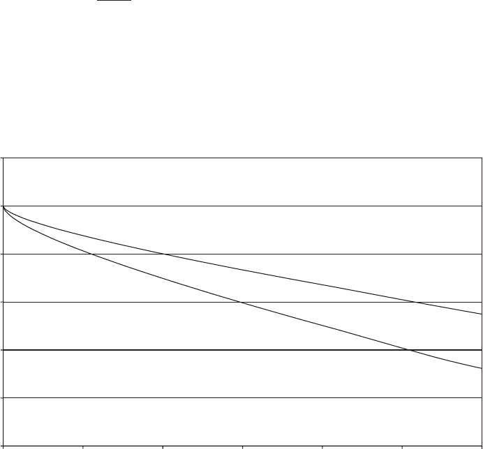
The buckling strength of a mild-steel cylinder in bending as a fraction of the yield
strength is plotted against the radius to wall-thickness ratio for imperfection ratios
(w=L) of 1 percent and 2 percent on Figure 7.39.
The effect of the choice of tower base diameter on total tower weight is best
illustrated by reference to a concrete example. Consider the design of a 50 m hub
0
0.2
0.4
0.6
0.8
1
1.2
0 50 100 150 200 250 300
Radius to thickness ratio, r /t
Buckling strength/yield strength
Imperfection to length ratio, w/L = 0.01
Imperfection to length ratio, w/L = 0.02
Figure 7.39 Buckling Strength in Bending of Thin-walled Mild-steel Cylinder for Varying
Radius to Thickness Ratio and Different Levels of Imperfection Based on ECCS Rules
TOWER 457
height tower in mild steel for a 60 m diameter, three-bladed, stall-regulated turbine
at a site with a 60 m/s extreme wind speed. The tower base wall thickness required
to resist the overturning moment produced by this wind speed has been calculated
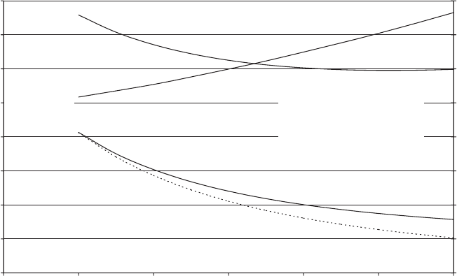
for a range of tower base diameters with the aid of Eq uation (7.71) and plotted on
Figure 7.40. Corresponding tower weights have also been plotted, based on a tower
top diamete r and wall thickness of 2.25 m and 11 mm respectively and assuming an
idealized linear wall-thickness variation between tower top and tower base. It can
be seen that the tower weight reaches a minimum value at about 4.5 m diameter,
indicating that beyond this point the reduction in cross-sectional area for constant
section modulus is offset by the effects of the reducing buckling strength and the
increasing wind loading on the tower itself. The weight penalty resulting from
restricting the tower base diameter to 4.0 m for transport purposes would, in this
case, be negligible.
Fatigue design
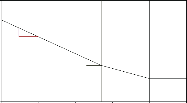
Clear rules for the fatigue design of steel-welded structures are given in Eurocode
3, where a family of S– N curves is defined for different weld details. On a log–log
plot these curves in fact consist of two straight lines, with slopes of 1/5 and 1/3 for
numbers of cycles above and below 5 3 10
6
respectively. In addition, there is a cut-
off limit at N ¼ 10
8
cycles, so that stress cycles with a stress rang e smaller than that
defined at 10
8
cycles are deemed not to cause any fatigue damage at all.
Excluding the tower doorway (which is considered later) the critical weld details
on a steel tubular tower are likely to be at welded attachments for intermediate
0
10
20
30
40
50
60
70
80
2 2.5 3 3.5 4 4.5 5
Tower base diameter (m)
Tower base wall thickness (mm) and tower weight (tonnes)
0
0.1
0.2
0.3
0.4
0.5
0.6
0.7
0.8
Tower natural frequency (Hz)
Tower base
wall thickness (mm)
Tower weight
(tonnes)
Natural frequency
(Hz)
Tower base wall thickness to maintain
constant section modulus cf 2.5 m dia (dotted line)
Steel yield stress = 245 MPa
No of blades = 3, Blade area = 50 sq m
Tower head mass = 75 tonnes
Tower top diameter = 2.25 m
Tower top wall thickness = 11 mm
Shear exponent = 0.11
Dynamic magnification factor = 1.12
Figure 7.40 Variation in Tower Base Wall Thickness with Diameter Required for Support of
60 m Diameter Stall-regulated Wind Turbine at 50 m Height in 70 m/s Extreme Wind
458
COMPONENT DESIGN
platform and cable support members and the horizontal welds to the tower base
flange and intermediate bolted flanges. Assuming a full penetration butt weld is
provided, the detail category number for the horizontal welds is 71 (where the
number 71 indicates the stress range applicable at 2 3 10
6
cycles in MPa). The detail
category number for longitudinal welded attachments reduces as the length of the
attachment increases, but if the attachment length can be restricted to 100 mm, the
detail category number of 71 applies here as well. The S– N curve for this detail
category is shown in Figure 7.41.
Eurocode 3 lays down different partial safety factors for fatigue strength, ª
Mf
,
according to the consequences of fail ure and the ease of inspection. If the local
failure of a component does not lead rapidly to the failure of the structure, then it is
termed ‘fail-safe’, and ª
Mf
¼ 1:0 provided the joint detail is accessible for inspec-
tion. On the other hand, ª
Mf
¼ 1:25 for an accessible non ‘fail-safe’ component. The
factors increase to 1.15 and 1.35 respectively for joint details that are difficult to
access. In a welded tubular structure, there is no barrier to the propagation of a
fatigue crack that has reached a critical length, so the welds have to be considered
non-fail-safe. Given that the tower welds are visible and accessible with relative
ease from inside the tower, a partial safety factor for fatigue strength of 1.25 would
appear reasonable.
The derivation of fatigue load spectra and the combination of stress ranges due to
M
X
and M
Y
load spectra are discussed in Section 5.12.6.
Relative criticality of extreme and fatigue loads
The relative criticality of buckling failure (under extreme loads) and fatigue loads
depends on a variety of factors. However, fatigue is more likely to be critical on
pitch-regulated machines than on stall-regulated ones, because of the increased
10
100
1000
Number of cycles,
N
Stress range (MPa)
29 MPa
52 MPa
414
m
= 3
m
= 5
1
m
5 x 10
7
10
8
10
4
10
5
10
6
10
7
10
8
10
9
Figure 7.41 Eurocode 3 Fatigue Strength for Detail Category 71 (Butt-welded Joint)
TOWER 459
rotor thrust fluctuations above rated and the reduced extreme loading at standstill.
Fatigue is also more likely to be critical at low wind-speed sites, because the
percentage reduction in extreme loads is less than the percentage reduction in
fatigue equivalent load.
Tuning of tower natural frequency
Considerable scope exists, at least in theory, for adjusting the tower natural
frequency to a suitable value by varying the base diameter, while maintaining the
necessary strength against extreme and fatigue loading. The effect on natural
frequency of varying tower base diameter by a factor of two, for a case where
extreme loading governs, is illustrated for a 60 m diameter stall-regulated machine
at 50 m hub-height in Figure 7.40. The frequency increases from 0.517 Hz for a
2.5 m base diame ter to 0.765 Hz for a 5.0 m diameter. Now the rotatio nal speed of a
60 m diameter turbine to yield a 60 m/s tip speed is about 19 r.p.m. If we assume
that the machine is two speed, with a lower rotational speed of 19 3 2=3 ¼
12:67 r:p:m:, then the lower blade passing frequency will be 0.633 Hz, right in the
middle of the available tower natural frequency range. Adopting a þ15%/15%
frequency exclusion zone, the tower natural frequency is required to be less than
0.538 Hz or more than 0.728 Hz. However, a frequency of 0.728 Hz would require a
diameter of about 4.7 m (without making the tower wall thicker than necessary for
the strength requirement), which is likely to be ruled out by transport considera-
tions. Thus the only strength limited design option is one with a base diameter of
2.75 m, with a weight penalty of about 10 T compared with the 60 T optimum
design, giving a natural frequency of about 0.535 Hz. Alternatively a 4 m base
diameter could be chosen and the wall thickness increased by 37% to 27.5 mm to
give a frequency of about 0.728 Hz. However, the weight penalty in this case is over
15 T.
The above case study illustrates the fact that it is not always economic to satisfy
the natural frequency requirements for a particular co mbination of turbine and hub
height. In these circumstances it may well be preferable to change the hub height.
For example, a hub height of 55 m would work much better for the case described,
with a tower base diameter of 3.5 m yielding a natural frequency of 0.535 Hz and a
tower weight of 74 T.
Joints between tower sections
Towers are normally fabricated in several sections for transport reasons, so joints
are required. Welding on site is an expensive operation, so bolted joints are almost
always used, although sleeved joints, in which each tapered tower section is
threaded over the one beneath and forced into place by jacking, have been used
successfully.
The structurally most effective joint is made with friction grip bolted splice plates
oriented vertically and sandwiching the walls of the abutting tower sections be-
tween them. Provided the grip force is adequate, the joint will not slip even under
460 COMPONENT DESIGN
the extreme load, with the result that the bolts are not subject to fatigue loads.
Unfortunately, apart from the effect of splice plates on the external appearance,
there are practical difficulties of joint assembly, because bolting requires the
provision of some form of personnel access on the outside of the tower. Neverthe-
less splice plates are used on some towers.
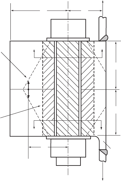
The most popular bolted arrangement is the internal flanged joint as illustrated in
Figure 7.42. The flanges are butt welded to the ends of the mating sections, with the
flange outer edge flush with the tower wall. Alternatively the flange may be formed
with a stu b section of tower wall already attached. Such flange s, which are termed
weld neck flanges, provide a smoother transition from wall to flange (as illustrated
in the lower half of Figure 7.42) and result in a higher butt-weld fatigue category.
After assembly, each bolt is torqued or tensioned to induce a preload between the
flanges in order to minimize in-service bolt fatigue stresses. The bolt should be
initially sized to resist the prying force induced by the extreme tower-wall tensile
stresses – taking the fulcrum adjacent to the flange inner edge – and then checked
for fatigue.
The fatigue calculation for the bolts in a flanged joint depends on the relationship
between the bolt load and tower wall stress, which only remains linear while
contact is maintained over the full flange width. The VDI Guideline (Verein
a
b
t
t
x
Z
Boundary of
compressed
volume
Weld nec
k
X
Equivalent
cylindrical
annulus
R
R
Z
P
/
2
P
/
2
P
/
2
P
/
2
Figure 7.42 Bolted Flange Joint
TOWER 461

Deutscher Ingenieure, 1986), VDI 2230, gives a method for calculating the bolt load
increment as a proportion of the load increm ent in the ‘tributary’ width of tower
wall under these conditions. The axial loading on the flanged joint and the effect of
the moment due to the eccentricity of loading are considered separately. The axial
load is assumed to be shared between the bolt and the preloaded flanges in
proportion to the stiffnesses of the load paths, which, in the case of the flanges, is
based on a reduced cross-sectional area related to the volume compressed by the
preload according to
A
ers
¼
4
d
2
w
d
2
h
þ
8
d
w
D
A
d
w
ðÞ
x þ 1
ðÞ
2
1
hi
where x ¼
ffiffiffiffiffiffiffiffiffiffi
l
k
d
w
D
2
A
3
s
(7:72)
and d
w
is the washer face diameter on the bolt head and nut, d
h
is the bolt hole
diameter, l
k
is the clamping length between bolt head and nut, and D
A
is twice the
distance from the bolt centreline to the nearest flange edge, or the bolt spacing,
whichever is the less.
The Guideline recognizes that the effective plane of introduction of the external
load will not necessarily be immediately under the bolt head or nut, but may lie
nearer the flange mid-plane, giving the load paths distinguished by different cross
hatching in Figure 7.42. Stresses due to the eccentricity of the tower wall load to the
flange contact area are dealt with by ordinary bending theory applied to the whole
contact area.
The VDI 2230 method outlined above no longer applies once a gap has opened
up between the flanges at the outer edge. For larger fluctuations in the externally
applied load, Z, the fulcrum model can be used, although it is inevitab ly conserva-
tive at low loads. The axial load, P, applied to the bolt/flange combination is
calculated on the basis that a fulcrum exists at X, a distance x from the bolt, so that
P ¼ Z(1 þ b=x), and the load share between the bolt and the compressed volume of
flange is calculated according to the relative stiffnesses as before.
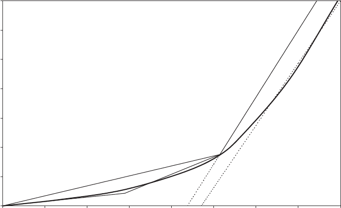
In Figure 7.43, the two linear relationships between bolt load increment and
externally applied load are compared with experimental results for a particular test
specimen with a single flange bolt. It is assumed that the planes of introduction of
the load on the bolt/flange combination are immediately under the bolt head and
nut in each case. Line OA shows the VDI 2230 model, with the point A representing
the limit of its validity. Line OB shows the fulcrum model, with B representing the
point at which the preload between the flanges at the position of the bolts
disappears. Thereafter, the bolt load varies as Z(1 þ b=x), i.e. along line BC for
x=a ¼ 0 :7. It may be noted from Figure 7.43 that a value of x=a of 0.8 results in better
agreement with the test results at high loads, but these are not of interest for design
purposes.
Schmidt and Neuper (1997) have proposed a more sophisticated model identified
as ‘Model C’, which combines aspects of the two models already described and
gives a bolt load characteristic consisting of the three straight lines OA, AB and BC
(see Figure 7.43). Clearly this agrees much better with the experimental results, but
it adds to the complexity of the fatigue load calculation.
Uniformity of bolt loading around the tower clearly depends on the accuracy of
the mating flange surfaces. Schmidt, Winterstetter and Kramer (1999) have investi-
462 COMPONENT DESIGN
gated the effects of various imperfections using a finite-element model and made
tentative suggestions regarding permitted tolerance levels.
Tower tie-down
The tower is normally fitted with a base flange, which can either be attached to the
foundation by screwed rods cast into the concrete or bolted to an embedded tower
stub. This sub section is concerned with the former arrangement.
The screwed rods are normal ly anchored in some way at their base, and their
capacity to resist overturning moment is determined by the pull-out resistance of
the semi-circle of bolts on the upwind side. As this is governed by the concrete
shear strength, the rods have to be anchored quite deep into the concrete, so that
their length is typically similar to the tower base radius.
The fatigue loads in the tie-down rods can be considerably reduced by pre-
tensioning. The share of tower-wall uplift loads taken by the rods can be based on an
estimate of the relative stiffnesses of the rod and the loaded volume of the concrete,
assuming a dispersion angle of about 308 in the radial direction. The screwed rods
should be sheathed, so that the pre-tension is applied over the full length.
Tower doorways
A doorway is required for access at or near the tower base, and additional
doorways are sometimes required for a transformer in the tower base or for
0
0.1
0.2
0.3
0.4
0.5
0.6
0.7
0 0.1 0.2 0.3 0.4 0.5 0.6 0.7 0.8
Externally applied load/Bolt preload Z /F
v
Bolt load increment/Bolt preload (F-F
v
)/F
v
A
B
C
Open joint model
with x = 0.7a
Open joint model
with x = 0.8a
Line OA: VDI 2230 model - applicable before flange separation begins
Line OB: Fulcrum model with bolt load share in proportion to VDI 2230 stiffnesses
Line OABC: Schmidt and Neuper Model C
Line BC: Open joint model with x = 0.7a
Heavy line: Experimental results
Joint Geometry:
a = 50 mm, b = 45 mm
t = 50 mm, bolt diameter = 30 mm
bolt spacing = 90 mm
Figure 7.43 Flange Joint Bolt Load Variation with Externally Applied Load – Experimental
Results and Engineering Models Compared
TOWER 463
maintenance access to the blade tip mechanism. Typically they have vertical sides
with sem i-circular ends at top and bottom. Vertical stiffeners have to be provided
as standard down each side to compensate for the missing section of wall and to
resist compression buckling, but attention has to be paid to the weld detail at the
stiffener ends, where stress concentration due to the opening is likely to be an
additional factor.
The weld detail at the stiffener end can be eliminated by reinforcing the inside
edge of the doorway with a continuous flange all the way round. The detail
category of the flange to tower wall butt weld under transverse loading is then 71,
but there is no stress concentration factor to contend with at the top and bottom of
the doorway.
7.9.4 Steel lattice towers
Steel lattice towers are usually assembled from angle sections, with bolting used for
attaching the bracing members to the legs and splicing the leg sections together.
Typically the towers are square in plan with four legs, facilitating the attachment of
the bracing members.
One of the advantages of lattice towers is that material savings can be obtained
by splaying the legs widely apart at the base, without jeopardizing stability or
posing transport problems. The latitude for doing this higher up is limited by tip
clearance considerations, so waisted tower designs are common. A more elegant
tower design results if the legs are rolled to a gentle concave curve, however.
The loads in the legs (or ‘chords’) res ult from the tower bending moments, while
the loads in the bracing (or ‘web’) members result from a combination of tower
shear and torsional loads. In eac h case member buckling under extreme loads has
to be considered, and fatigue loading at the joints. Two devices are employed to
improve member stability: the web members are arranged as pairs of intersecting
diagonals rather than adopting a single triangulated system, so that the tension
diagonal can stabilize the compression diagonal at each intersection, and the web/
chord intersection points on either side of each chord member are staggered
vertically to reduce the spacing of chord supports restraining flexure about the
minor axis. Note that care with detailing is needed at the waist, if present, in order
to ensure adequate lateral restraint for the chords at the change of direction.
Fatigue loading of bolts is avoided by the use of friction grip bolts. Accordingly
galvanizing is normally used for corrosion protection rather than painting, in order
to achieve an adequate coefficient of friction.
7.10 Foundations
The design of wind-turbine foundations is largely driven by the tower base over-
turning moment under extreme wind conditions. A variety of slab, multi-pile and
mono-pile solutions have been adopted for tubular towers, and these are discussed
in turn below.
464 COMPONENT DESIGN