Burton T. (et. al.) Wind energy Handbook
Подождите немного. Документ загружается.


r
A
is the annulus radius and r
S
is the sun radius. Hence, putting a ¼ r
A
=r
S
, the
volume of a planet is
k
B
T
LSS
1:15(a 1)
(a þ 1)
2
r
S
2d
PL
z
1
lim
and the volume of the sun is 4=(a 1)
2
times as big. The total volume of planets and
sun becomes
V ¼ k
B
T
LSS
1
a þ 1
2d
PL
z
1
r
S
lim
1 þ
4
(a 1)
2
N
(7:56)
Substituting a ¼ 2, we obtain
d
PL
¼ r
s
and N ¼
3
1:15
¼ 8:195
which is rou nded down to 8, giving
V ¼ k
B
T
LSS
2z
1
3
lim
1 þ
4
8
¼ k
B
T
LSS
z
1
=
lim
Hence the volume of the sun and planets of the epicyclic stage is only one eighth of
the volume of the gearwheel and pinion of the equivalent parallel stage, assuming
the designs are governed by gear tooth bending stress. If contact stress were to
govern, the relative volume of the epicyclic stage would be even less.
The dramatic materials savings obtainable with epicyclic gearboxes depend on
equal sharing of loads between the planets. Although this is theo retically achievable
through accuracy of manufacture, it is in practice desirable to introduce some
flexibility in the planet mountings to take up any planet position errors – for
example by supporting the planets on slender pins cantilevered out from the planet
carrier. Note that the fatigue design of such pins is, like the design of intermediate
shafts, governed by torque fluctuations rather than by torque absolute magnitude.
7.4.8 Gearbox noise
The main source of gearbox noise arises from the meshing of individual teeth.
Loaded teeth deflect slightly, so that if no tooth profile correction is made, unloaded
teeth are misaligned when they come into contact, resulting in a series of impacts at
the meshing frequency. It is therefore standard practice to adjust the tooth profile –
usually by removing material from the tip area of both gears, referred to as ‘tip
relief’ – to bring the unloaded teeth back into alignment at the rated gear loading.
In the case of wind turbines, the gear loading is variable, so it is necessary to select
the load level at which the tip relief provides the correct compensation. If the tip
relief load level is too high, there will be exce ssive loss of toot h contact near the tips
at low powers, while if it set too low the noise level at rated power will be too high.
GEARBOX 435
However, if gearbox noise is expected to be more intrusive at low wind speeds,
when it is less likely to be masked by aerodynamic noise, then a low compensation
load level should be selected.
Helical gears are usually quieter than spur gears (with teeth parallel to the gear
axis) because the width of the tooth comes into mesh over a finite time interval
rather than all at once. Moreover, the peak tooth deflections of helical gears are less
than those of spur gears because there are always at least two teeth in contact rather
than one, and because the varying bending moment across the tooth width means
that the less heavily loaded portions of the tooth can provide restraint to the part
that is most heavily loaded. As a result, the tooth misalignments due to insuffi-
cient/excessive tip relief at a particular load level will be reduced .
Epicyclic gears are normally quieter than parallel shaft gears because the reduced
gear size results in lower pitch line velocities. However, this benefit is lost if spur
gears are used rather than helical gears, in order to avoid problems with planet
alignment. One way of maintaining the alignment of helical planet gears is to
provide thrust collars on the sun and annulus.
As the annulus of an epicyclic gear stage is often fixed, it would be convenient to
integrate it with the gearbox casing. However, this would enable annulus gear
meshing noise to be radiated directly from the casing, so it is preferable to make the
annulus a separate element, supported on resilient mountings. Similarly, resilient
gearbox mountings should be used to attenuate the transmission of gearbox noise
to the nacelle structure and tower.
The noise produced by gear tooth meshing can reach the environment outside
the wind turbine by a variety of routes:
• through the shaft directly to the blades, which may radiate efficiently,
• through the resilient mounts of the gearbox to the support structure and thereby
to the tower, which can radiate efficiently under some circumstances,
• through the resilient mounts of the gearbox to the support structure and thereby
to the nacelle structure, which can also radiate,
• through the casing wall to the nacelle air and then via air intake and exhaust
ducts,
• through the casing wall to the nacelle air and then via the nacelle structure.
All these paths are modally dense and it is virtually impossible to design out a
selected frequency. If noise is a problem then the options are to reduce the source
sound level, perhaps by improving the tip relief as described above, or to modify
the major path to reduce transmission. Identification of the major path is not
straightforward, but one way of doing so is to use Statistical Energy Analysis (SEA),
which combines a theoretical model with extensive field measurements. The path
may not be simple, as non-linearity in the system can make one path the predomi-
nant one at low wind speeds and another path critical at higher wind speeds.
Treatment of a radiating path can invo lve damping treatment such as shear layer
436 COMPONENT DESIGN
damping or even just sand or bitumen layers added to the tower wall, for instance.
In some cases the treatment can have more than one effect. When blades are the
major source of radiation and damping material is added inside the blades then this
material can act as a stiffening material as well as a damping mechanism. Some-
times it is useful to add tu ned absorbers to parts of the structure to damp out one
particular frequency. An alternative use of such tuned absorbers is to design them
to raise the impedance at the tuned freque ncy so that the offending vibration does
not pass that point on the structure.
7.4.9 Integrated gearboxes
As noted in Section 6.11.1, the cases of integrated gearboxes must be very robust, in
order to transmit the rotor loads to the nacelle structure without exp eriencing
deflections which would impair the proper functioning of the gears. In view of the
complex shape of the casing, stress distributions due to each load vector usually
have to be det ermined using finite-element (FE) analysis – these can then be
superposed in line with the different extreme load combinat ions. The fatigue
analysis will require the superposi tion of stress histories resulting from simultane-
ous time histories of rotor thrust, yaw moment and tilt moment derived from
simulations at different wind speeds.
7.4.10 Lubrication and cooling
The function of the lubrication system is to maintain an oil film on gear teeth and
the rolling elements of bearings, in order to minimize surface pitting and wear
(abrasion, adhesion and scuffing). Varying levels of the elastohydrodynamic lubri-
cation provided by the oil film can be identified, depending on oil film thickness.
These range from full hydrodynamic lubrication, which exists when the metal
surfaces are separated by a relatively thick oil film, to boundary lubrication when
the asperities of the metal surfaces may be separated by lubricant films only a few
molecular dimensions in thickness. Scuffing, which is a severe form of adhesive
wear involving localized welding and particle transfer from one gear to the other,
can occur under boundary lubrication conditions, which are promoted by high
loading and low pitch line velocity and oil viscosity.
Two alternative methods of lubrication are available: splash lubrication and
pressure fed. In the former, the low-speed gear dips into an oil bath and the oil
thrown up agains t the inside of the casing is channelled down to the bearings. In
the latter, oil is circulated by a shaft driven pump, filtered and delivered under
pressure to the gears and bearings. The advantage of splash lubrication is its
simplicity and hence reliability, but pressure fed lubrication is usually preferred for
the following reasons:
• oil can be positively directed to the locations where it is required by jets,
• wear particles are removed by filtration,
GEARBOX 437
• the churning of oil in the bath, which can result in a net efficiency loss, is avoided,
• the oil circulation system enables heat to be removed much more effectively from
the gearbox by passing the oil through a cooler mounted outside the nacelle,
• it allows for intermittent lubrication when the machine is shut-down if a standby
electric pump is incorporated.
With a pressure fed system, it is normal practice to fit temperature and pressure
switches downstream of the filter to trip the machi ne for excessive temperature or
insufficient pressure.
Guidance on the selection of lubricant, which has to take into account the ambient
temperatures at the site in question, is given in the AGMA/AWEA (1996) docu-
ment. Sump heaters may be needed to enable oil to be circulated when the turbine
starts up at low temperatures.
7.4.11 Gearbox efficiency
Gearbox efficiency can vary between about 95 percent and 98 percent, depending
on the relative number of epicyclic and parallel shaft stages and on the type of
lubrication.
7.5 Generator
7.5.1 Induction generato rs
The induction generators commonly used on fixed-speed wind turbines are very
similar to conventional industrial induction motors. In principle the only differ-
ences between an induction machine operating as a generator and as a motor are
the direction of power flow in the connecting wires, whether torque is applied to or
taken from the shaft and if the rotor speed is slightly above or below synchronous.
The size of the market for induction motors is very large and so, in many cases, an
induction generator design will be based on the same stator and rotor laminations
as a range of induction motors in order to take advantage of high manufacturing
volumes. Some detailed design modifications, e.g., changes in rotor bar material,
may be made by the machine manufacturers to reflect the different operating
regime of wind turbine generator, particularly the need for high efficiency at part
load, but the principles of operation are those of conventional ind uction motors.
The synchronous speed, which is determined by the number of magnetic poles
will be in the range of 1500 r.p.m. (4 pole), 1000 r.p.m. (6 pole) or 750 r.p.m. (8 pole)
for connection to a 50 Hz network. For commercial reasons it is common to use a
voltage of only 690 V even for large generators and in some very large wind
turbines the resulting high currents have led to the decision to locate the turbine
transformer in the nacelle. The physical protection of the generator is arranged to
avoid the ingress of moisture, i.e. a totally enclosed design, and in some wind
438 COMPONENT DESIGN
turbines liquid cooling is used to reduce air-borne noise. A high slip at rated power
output is often requested by the wind turbine designer as this increases the
damping in the wind turbine drive train but at the expense of losses in the rotor.
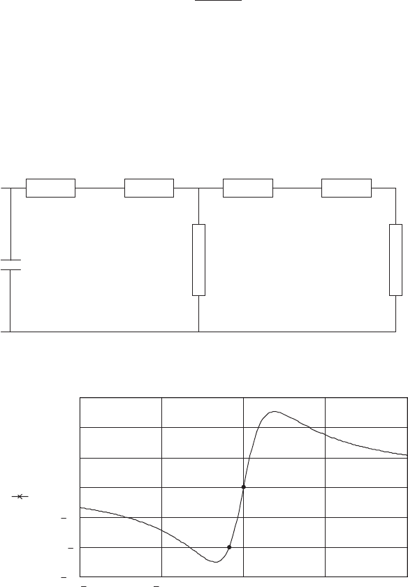
Figure 7.28 shows the conventional equivalent circuit of an induction machine
that may be used to analyse its steady-state behaviour (Hindmarsh, 1984, and
McPherson, 1990). The slip (s) is the difference between the angular velocity of the
stator and rotor:
s ¼
ø
s
ø
r
ø
s
(7:57)
and so for motor operation it is positive and for generator operation negative.
Figure 7.29 shows how the active power varies with slip for a 1 MW induction
machine. A convention has been chosen with the current flowing into the circuit
and so the norm al operating region for a generator is between O and A. At 1 MW
generation (A) the slip is around 0.8 percent with the rotor rotating faster than the
stator field. It may be seen that the maximum power that may be generated before
the peak of the curve is reached is only some 1.3 MW. This is because the generator
R
s
jX
s
jX
r
R
r
⫺jX
c
jX
m
R
r
(1 ⫺ s)/s
Figure 7.28 Equivalent Circuit of an Induction Machine with Power Factor Correction
Capacitors
1.5
1
0.5
0
0.5
1
1.5
10% 5% 0 5% 10%
Real power
(MW)
Slip
motoring
generating
O
A
Figure 7.29 Variation of Active Power with Slip of a 1 MW Induction Machine
GENERATOR 439
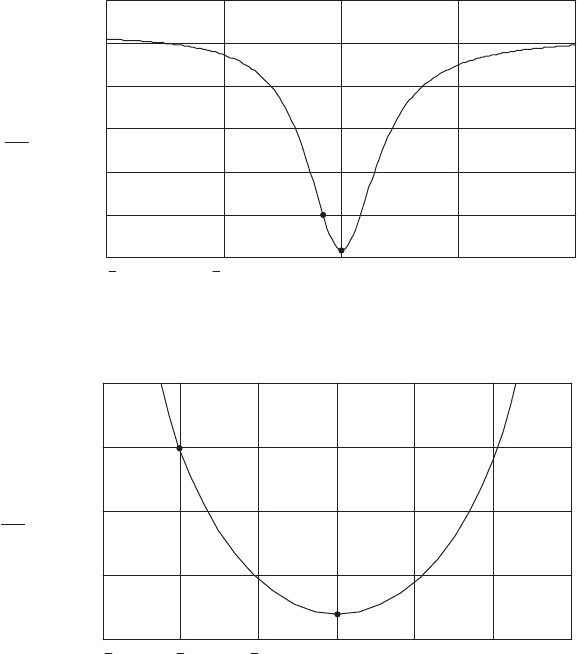
has been represented as connected to a distribution network with a low short-circuit
level (and hence a high impedance) and the impedance of the local turbine
transformer is included in the calculation. This source impedance acts to lower the
maximum power which may be exported before the peak of the curve is reached,
and instability occurs. It also leads to asymmetry in the torque–slip curve.
Figure 7.30 shows how the reactive power drawn by the generator varies with
slip. The normal generating operating region is again shown as O–A. At point A
(1 MW output) the generator (with its fixed local power factor correction capacitors)
draws some 600 kVAr. It may be seen that the reactive power requirement increases
very rapidly if the output power rises above its rated value.
Figures 7.29 and 7.30 may be combined to give the conventional ‘circle diagram’
representation of an induction machine shown in Figure 7.31. Again the normal
generating region is shown as O–A. The fixed power factor correction capacitors
act to reduce the requirement for reactive power and so translate the circle diagram
on the y-axis towards the origin.
Reactive power
(MVAr)
0
0.5
1
1.5
2
2.5
3
10% 5% 0 5% 10%
Slip
A
O
Figure 7.30 Variation of Reactive Power with Slip for a 1 MW Induction Machine
Reactive power
(MVar)
0
0.2
0.4
0.6
0.8
1.5 1 0.5 0 0.5 1 1.5
Real power (MW)
A
O
Figure 7.31 Circle Diagram of 1 MW Induction Machine
440
COMPONENT DESIGN
The equations used to describe the steady-state performance of induction gen-
erators are given in any standard undergraduate textbook (e.g. Hindmarsh, 1984,
and McPherson, 1990). Dynamic analysis is more complex but is dealt with by
Krause (1986).
7.5.2 Variable-speed generators
There are two fundamental approaches to electrical variable-speed operation. Either
all the output power of the wind turbine may be passed through the frequency
converter to give a broad range of variable speed operation or a restricted speed
range may be achieved by converting only a fraction of the output power.
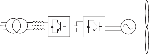
Figure 7.32 shows in schematic form how a broad range, variable-speed genera-
tion system may be configured. Early broad range variable-speed wind turbines
used a diode rectifier bridge in the generator converter and a naturally commu-
tated, thyrist or, current source, converter on the network side (Freris, 1990). How-
ever, naturally commutated thyristor converters consume reactive power and
generate considerable characteristic harmonic currents. On weak distribution sys-
tems it is difficult to provide suitable filtering and power factor correction for this
type of equipment. Hence modern practice is to use two voltage source converters
(Heier, 1998) with either a synchronous or induction generator. Each converter
consists of a Graetz Bridge (as shown in Figure 10.17) with Insulate d Gate Bipolar
Transistors (IGBTs) as the switching elements. The bridges are switched rapidly
(typically between 2–6 kHz) with some form of Pulse Width Modulation to produce
a close approximation to a sine wave. The generator converter rectifies all the power
to DC, which is then inverted by the network converter. Ope ration of this type of
voltage source converter is described in Mohan, Undeland and Williams (1995).
Control strategies vary but one appr oach is to control the generator converter to
maintain the DC link voltage at a constant value and then use the network converter
to control the power flowing out of the system and hence the torque on the
generator (Jones and Smith, 1993). A power bandwidth of 200–500 radians/s is
quoted in this paper indicating the very fast control possible with such equipment
with an overall efficiency of 92.1 percent consisting of 95.9 percent for the generator
and 96 percent for the power electronics. The network side converter may be
Generator
converter
Network
converter
Local
transforme r
Figure 7.32 Broad Range Variable Speed Generation
GENERATOR 441
arranged to operate at any power factor within the rating of the equipment with
very low harmonic distortion.
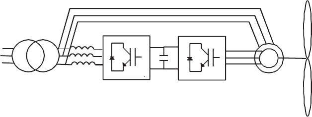
Figure 7.33 shows how narrow band variable speed control may be implemented.
A wound rotor induction generator is used and control is possible over all four
quadrants of speed and torque. The generator stator is connected directly to the
network with a frequency converter in the rotor circuit. This ‘doubly fed’ concept
was used in early large prototype wind turbines, e.g., the 3 MW Growian con-
structed in Germany in the early 1980s (Warneke, 1984) and the Boeing MOD 5B in
the USA at the same time. At that time, cyclo-converters were used to change the
frequency of the rotor circuit but modern practice is to use two voltage source
converters similar to the broad range variable -speed designs but having a lower
power rating. Again, control techniques vary but one approach is to use vector
control techniques on the machine side converter to adjust torque and the excitation
of the generator independently. The network side bridge maintains the DC link
voltage and supplies additional reactive power to maintain the power factor of the
wind turbine (Pena, Clare and Asher, 1996). Doubly-fed inducti on generators are
becoming increasingly common in large wind turbines where the benefits of limited
variable-speed operation are required but at the reduced cost of controlling only a
fraction of the output power. A possible future development is the use of the
brushless doubly-fed generator where rather than use slip rings the rotor is excited
by a second controlled stator winding. This approach eliminates the requirement
for slip-rings and brushes but is not yet used commercially.
7.6 Mechanical Brake
7.6.1 Brake duty
As indicated in Sectio n 6.8.3, a mechanical brake can be called on to fulfil a variety
of roles, according to the braking philosophy adopted for the machine in question.
The minimum requirement is for the mechanical brake to act as a parking brake, so
that the machine can be stopped for maintenance purposes. The brak e will also be
Rotor
circuit
Stator
circuit
Local
transformer
Wound rotor
induction
machine
Figure 7.33 Narrow Range Variable Speed Generation
442
COMPONENT DESIGN
used to bring the rotor to a standstill during high wind shut-downs for the majority
of machine designs, and during low-speed shut-downs as well in some cases.
Aerodynamic braking is used to decelerate the rotor initially, so the mechanical
brake torque can be quite low. However, IEC 61400-1 requires that the mechanical
brake be capable of bringing the rotor to a complete stop from a hazardous idling
state in any wind speed less than the 1 year return period 3 s gust (see Table 5.1).
If the mechanical brake is required to arrest the rotor in the event of a complete
failure of the aerodynamic braking system, then there are two deployment options
to consider. Either the mechanical brake can be actuated when an overspeed
resulting from the failure of the aerodynamic system is detected, or actuated
simultaneously with the aerodynamic brake as part of the standard emergency
shut-down procedure. The advantage of the former strategy is that the mechanical
brake will rarely, if ever, have to be deployed in this way, so that some pad or even
disc damage can be tolerated when deployment actually occurs. In addition, fatigue
loading of the gearbox will be reduced if the brake is mounted on the high-speed
shaft. On the other hand, if the mechanical brake is actuated before significant
overspeed has developed, then the aerodynamic torque to be overcome by the
mechanical brake in the event of aerodynamic braking failure will be less.
The most severe emergency braking case will arise following a grid loss during
generation in winds above rated. In the case of pitch-regulated machines, the
maximum overspeed will occur after grid loss at rated wind speed because the rate
of change of aerodynamic torque with rotational speed decreases and soon becomes
negative at higher wind speeds. Conversely, if the pitch mechanism should jam, the
braking duty becomes more severe at wind speeds at or above cut-out, because
much higher aerodynamic torques are developed as the rotor slows down and the
angle of attack increases. For stall-regulated machines the critical wind speed is
generally at an intermediate value between rated and cut-out.
7.6.2 Factors governing brake design
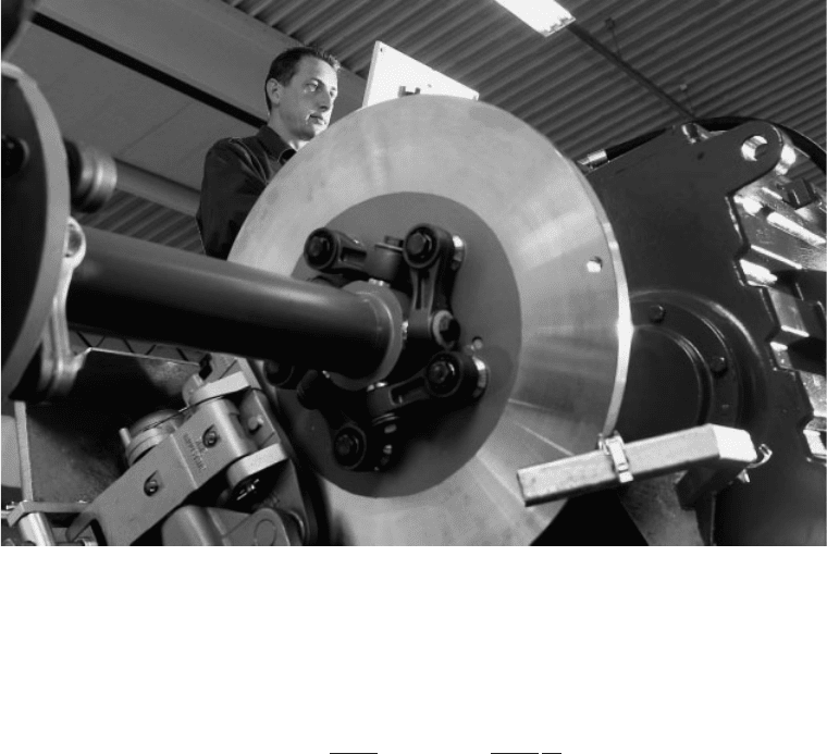
The braking torque provided by callipers gripping a brake disc (Figure 7.34) is
simply the product of twice the calliper force, the coefficient of friction (typically
0.4), the number of callipers and the effective pad radius. Callipers providing
clamping forces of up to 500 KN are avai lable. However, the brake design is also
limited by:
• centrifugal stresses in the disc,
• pad rubbing speed,
• power dissipation per unit area of pad, and
• disc temperature rise.
The nature of these constraints is described below.
The critical stress generated by centrifugal stresses is in the tangen tial directio n at
MECHANICAL BRAKE 443
the inner radiu s of the brake disc, but it is governed principally by the disc rim
speed according to the following formula:
Ł
(a) ¼
3 þ
4
rø
2
b
2
1 þ
1
3 þ
a
2
b
2
(7:58)
where a and b are the inner and outer disc radii respectively and ø is the disc
rotational speed. One brake manufacturer, Twiflex, quotes a maximum safe disc
rim speed of around 90 m/s for their discs manufactured in spheroidal graphite
cast iron.
Brake pads are generally made from sintered metal or a cheaper, resin-based
material. The former can accept rubbing speeds of up to 100 m/s, but some
manufacturers quote permitted rubbing speeds for the latter of only about 30 m/s.
However, Wilson (1990) reports satisfactory performance of resin-based pads at a
rubbing speed of up to 105 m/s if the power dissipation rate per unit area, Q,is
kept low enough. The criterion, ascribed to Fero do, is that Q ¼ PV <
11:6MW=m
2
, where is the coefficient of friction, P is the brake-pad pressure in
KN/m
2
and V is the rubbing speed in m/s. This requires the pad pressure to be
reduced to 275 KN/m
2
, assuming a friction coefficient of 0.4.
During braking the kinetic energy of the rotor and drive train together with the
additional energy fed in by the aerodynamic torque are dissipated in the brake disc
and pads as heat, resulting in rapid initial temperature rise near the surface of the
Figure 7.34 High-speed Shaft Brake Disc and Calliper (Reprodued by permission of NEG-
Micon)
444
COMPONENT DESIGN
