Burton T. (et. al.) Wind energy Handbook
Подождите немного. Документ загружается.

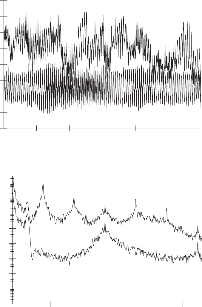
(kNm)
Time (s)
-50
-100
0
50
100
150
200
250
300
0 20406080100120
Out-of-plane
In-plane
Figure 5.34 Blade Root Bending Moment in Turbulent Wind
Auto spectral density ((Nm)
2
/Hz)
Frequency (Hz)
1.0e+03
1.0e+04
1.0e+05
1.0e+06
1.0e+07
1.0e+08
1.0e+09
1.0e+10
0.0 0.5 1.0 1.5 2.0 2.5 3.0 3.5 4.0 4.5 5.0
Hub thrust force
Blade root moment
Figure 5.35 Spectra of Out-of-plane Loads in Turbulent Wind
BLADE DYNAMIC RESPONSE 285
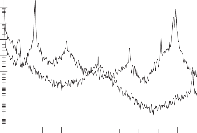
2P,4P etc. Only the peaks at multiples of 3P remain, since at these frequencies the
three blades act in phase with each other.
This effect is even more significant in the in-plane load spectra (Figure 5.36). Of
the blade load peaks at multiples of 1P, only the relatively small peaks at 3P and 6P
come through to the hub torque. The 1P peak in the blade load, which is dominated
by gravity, is particularly large, but it is completely eliminated from the hub torque.
The to wer peak at 0.4 Hz is visible in both loads. A large blade load peak at the first
in-plane blade vibrational mode at 4.4 Hz is also seen, but this is a mode which does
not include any rotation at the hub, and consequently is not seen in the hub torque.
Some higher frequency blade modes (not shown) will be coupled with hub rotation.
5.8.11 Ae roelastic stability
Aeroelastic instability can arise when the change in aerodynamic loads resulting
from a blade displacement is such as to exacerbate the displacement rather than
diminish it, as is normally the case. A theoretical example would be a teetering
rotor operating in stalled flow, where the rate of change of lift coefficient with angle
of attack is negative, so that the aerodynamic damping is negative likewise. In such
circumstances, teeter excursions would be expected to grow until the limits of the
negative damping band or of the teeter stops were reached. In practice, this
phenomenon can be avoided if the blade is designed so that the blade root flapwise
bending moment increases monotonically with wind speed over the full wind
speed operational range (Armstrong and Hancock, 1991).
Auto spectral density (N
2
/Hz)
Frequency (Hz)
1.0e+03
1.0e+04
1.0e+05
1.0e+06
1.0e+07
1.0e+08
1.0e+09
1.0e+10
0.0 0.5 1.0 1.5 2.0 2.5 3.0 3.5 4.0 4.5 5.0
Hub torque
Blade root moment
Figure 5.36 Spectra of In-plane Loads in Turbulent Wind
286
DESIGN LOADS FOR HORIZONTAL-AXIS WIND TURBINES
A real instance of incipient aeroelastic instability was the development of an
edgewise blade resonance under stalled conditions on some larger three-bladed
machines. A negative rate of change of lift coefficient with angle of attack is
believed to have been the prime cause – see Section 7.1.9.
Another potential instance of aeroelastic instability is classical flutter, encoun-
tered in the design of helicopter rotors, in which the blade structure is such that
out-of-plane flexure in the downwind direction results in blade twisting, causing an
increase in the angle of attack. During the development of some of the early large
machines, the dangers of aeroelastic instability were considered to be a real concern,
and much analysis work was directed to demonstrating that individual turbine
designs would not be susceptible to it. However, partly no doubt because of the
high torsional rig idity of the closed cell hollow structure adopted for most wind
turbine blades, aeroelastic instability has not yet been found to be critical in
practice, and stability analyses are no longer regarded as an essential part of the
design process. This may change, however, if designs become more flexible.
5.9 Blade Fatigue Stresses
5.9.1 Methodology for blade fatigue design
The v erification of the adequacy of a blade design in fatigue requires knowledge of
the fatigue loading cycles expected over the lifetime of the machine at different
radii, derivation of the resultant stress cycles and calculation of the corresponding
fatigue damage number in relation to kno wn fatigue properties of the material. The
procedure is less or more complicated, depending upon whether blade loading in
one or two planes is taken into account. If bending about only the weaker principal
axis is taken into account, considering only aerodynamic lift forces, the steps
involved are as follows.
(1) Derive the individual fatigue load spectra for each mean wind speed and for
each radius. This is a non-trivial task because, unless wind simulation is used,
the information on the periodic and stochastic load components is available in
different forms, i.e., as a time history and a power spectrum respective ly.
Sections 5.9.2 and 5.9.3 consider methods of addressing this difficulty.
(2) Synthesize the complete fatigue load spectrum at each radius from the separate
load spectra for each mean wind speed, including start-ups and shutdowns (see
Section 5.5.1).
(3) Convert the fatigue load cycles (expressed as bending moments) to fatigue
stresses by dividing by the appropriate sec tion modulus. (The section modulus
with respect to a particular principal axis is defined as Second Moment of Area
of the cross section about that axis divided by the distance of the point under
consideration from the axis.)
BLADE FATIGUE STRESSES 287
(4) Sum the fatigue damage numbers, n
i
=N
i
, according to Miner’s rule, for each
moment range ‘bin’ in the fatigue load spectrum, according to the appropriate
SN curve for the material. SN curves for different blade materials are
considered in Section 7.1.6 and 7.1.7, together with the allowance necessary for
mean stress.
Sections 5.9.2 and 5.9.3 are concerned with the first step of the sequence above. For
a given mean wind speed, the periodic component of blade loading will be invariant
over time, and the stochastic component will be stationary. As noted in Section 5.7.5,
the stochastic component can be analysed either in the frequency domain (provided
that a linear relationship between incident wind speed and blade loadings can be
assumed) or in the time domain, i.e., by using wind simulation. Section 5.9.2
considers how the deterministic and stochastic components may be combined if the
latter have been analysed in the frequency domai n, while Section 5.9.3 looks in detail
at the option of assessing fatigue damage completely in the frequency domain.
If the fatigue damage resulting from both in-plane and out-of-plane loading is to
be computed, it is necessary to revise the ordering of the steps above, in order to
derive the periodic and stochastic components of the stress variation for each point
under consideration and for each mean wind speed. For a chosen point, the
procedure becomes as shown below.
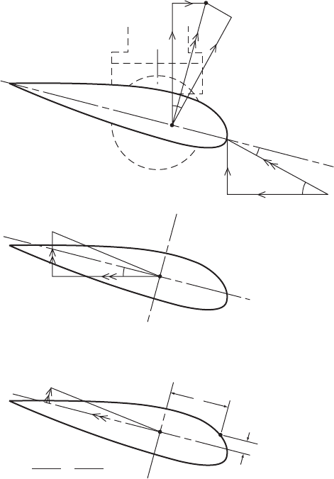
(A1) For a given mean wind speed, calculate the time histories of the bending
moments about the principal axes resulting from the periodic load compo-
nents over one blade rotation. The derivation of aerodynamic moments from
blade element loads is illustrated in Figure 5.37.
(A2) Convert these bending moment time histories to stress time histories by
dividing by the appropriate section modulus, and adding them together.
(B) For the same mean wind speed, convert the power spectrum of the stochastic
bending moment component (which, because of the linearity assumption,
arises from fluctuating lift only) to a power spectrum of stress at the chosen
point.
(C) Calculate the fatigue damage resulting from the combined periodic and
stochastic stress components, using the methods of Sections 5.9.2 and 5.9.3.
(D) Repeat the above steps for the other mean wind speeds.
(E) Add together the fatigue damages arising at each mean wind speed to obtain
the total fatigue damage during normal running.
5.9.2 Combination of deterministic and stochastic components
Previous sections have shown how the deterministic (i.e., periodic) and stochastic
components of blade bending moments can be characterized in terms of time
288 DESIGN LOADS FOR HORIZONTAL-AXIS WIND TURBINES
histories and power spectra respectively. Unfortunately the spectral description of
the stochastic loading is not in a suitable form to be combined with the time history
of the periodic loading, but this difficulty can be resolved by one of two methods, as
follows.
(1) The power spectrum of the stochastic component can be transformed into a time
history by inverse Fourier transform, which can then be added directly to the
time history of the periodic component. Applications of this method have been
reported by Garrad and Hassan (1986) and Warren et al. (1988). With the
subsequent development of wind simulat ion techniques, this method is no
longer commonly used, because the use of transformations to generate time-
histories of wind speed rather than of wind loading avoids the need to assume
that wind speed and wind loading are linearly related when deriving the power
spectrum of the stochastic load component.
Q
O
S
M
Y
M
X
V
V
θ′
O
S
M
uu
M
vv
M
uu
= M
y
cos θ' + M
x
sin θ'
F
x
= (C
l
cos φ + C
d
sin φ)
1
/
2
pW
2
. c(r)
⫺F
y
= (C
l
sin φ + C
d
cos φ)
1
/
2
pW
2
. c(v)
M
vv
= M
y
sin θ' + M
x
cos θ'
C
d
.
1
/
2
pW
2
. c(r)dr
C
l
.
1
/
2
pW
2
c(r).dr
⫺F
Y
.dr
F
X
.dr
V
u
P
U
U
U
U
V
v
M
uu
.u M
vv
.v
I
uu
I
vv
σ′
p
= –
(
+
)
M
x
= ∫(
⫺
F
y
)(r-r*)dv
R
r*
M
y
= ∫(F
x
)(r-r*)dv
R
r*
φ
φ
W
O
S
α
Figure 5.37 Derivation of Blade Bending Stresses at Radius r
due to Aerodynamic Loads
BLADE FATIGUE STRESSES 289

(2) A probability density function for the load cycle ranges can be derived
empirically, based on the spectral properties of the power spectrum of the
stochastic and periodic components of loading co mbined.
The second approach is considered in the next Section.
5.9.3 Fat igue prediction in the frequency domain
The probability density function (p.d.f.) of peaks of a narrow band, Gaussian
process are given by the well-know n Rayle igh distribution. As each peak is
associated with a trough of similar mag nitude, the p.d.f. of cycle ranges is Rayleigh
likewise.
Wind turbine blade loading cannot be co nsidered as narrow band, despite the
concentration of energy at the rotational frequenc y by ‘gust slicing’ (Section 5.7.5),
and neither can it be considered as Gaussian because of the presence of periodic
components. Dirlik (1985) produced an empirical p.d.f. of cycle ranges applicable to
both wide and narrow band Gaussian processes, in terms of basic spectral proper-
ties determined from the power spectrum. This was done by considering 70 power
spectra of vari ous shapes, computing their rainflo w cycle range distributions and
fitting a general expression for the cycle range p.d.f. in terms of the first, second and
fourth spectral moments. Dirlik’s expression for the cycle range p.d.f. is:
p(S) ¼
D
1
Q
e
Z=Q
þ
D
2
Z
R
2
e
( Z
2
=2R
2
)
þ D
3
Ze
( Z
2
=2)
2
ffiffiffiffiffiffiffi
m
o
p
(5:117)
where
Z ¼ S=
ffiffiffiffiffiffiffi
m
o
p
, D
1
¼
2(x
m
ª
2
)
1 þ ª
2
, D
2
¼
(1 ª D
1
þ D
2
1
)
1 R
, D
3
¼ 1 D
1
D
2
Q ¼
1:25(ª D
3
D
2
R)
D
1
, R ¼
ª x
m
D
2
1
(1 ª D
1
þ D
2
1
)
, x
m
¼
m
1
m
0
ffiffiffiffiffiffiffi
m
2
m
4
r
, ª ¼
m
2
ffiffiffiffiffiffiffiffiffiffiffiffiffi
m
0
m
4
p
,
m
i
¼
ð
1
0
n
i
S
(n)dnS
(n) is the power spectrum of stress,
and S is the cycle stress range:
Although the Dirlik cycle range p.d.f. was not intended to apply to signals
containing periodic components, several investigations (Hoskin et al. (1989), Mor-
gan and Tindal (1990), Bishop et al. (1991)) have been carried out to determine its
validity for wind turbine fatigue damage calculations, using monitored data for
flapwise bending from the MS1 wind turbine on Orkney. Cycle range p.d.f.s were
calculated from power spectra of monitored strains using the Dirlik formula and
fatigue damage rates derived from these p.d.f.s compared with damage rates
290 DESIGN LOADS FOR HORIZONTAL-AXIS WIND TURBINES
derived directly from the monitored signal by rainflow cycle counting. The ratio of
damage calculated by the Dirlik method to damage calculated by the rainflow
method ranged from 0.84 to 1.46, from 1.01 to 2.48 and from 0.73 to 2.34 in the three
investigations listed above, using a S=N curve exponent of 5 in each case, as the
blade structure was of steel. In view of the fact that the calculated damage rates
vary as the fifth power of the stress ranges, these results indicate that the Dirlik
method is capable of giving quite accurate results, despite the presence of the
periodic components.
There are two main drawbacks to the application of the Dirlik formula to power
spectra containing periodic components. First, the presence of large spikes in the
spectra due to the periodic components renders them very different from the
smooth distributions Di rlik originally considered, and second, information about
the relative phases of the periodic components is lost when they are transformed to
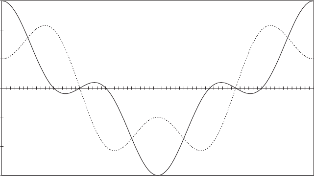
the frequency domain. Morgan and Tindal (1990) illustrate the effect of varying
phase angles by a comparison of plots of (cos øt þ 0:5 cos 3øt) and (cos øt
0:5 cos 3øt) which is reproduced in Figure 5.38. For a material with a S=N curve
exponent of 5, stresses conforming to the first time history would result in 5.25
times as much fatigue damage as stresses conforming to the second.
Bishop, Wang and Lack (1995) developed a modified form of the Dirlik formula
to include a single periodic component, using a neural network approach to
determine the different parameters in the formula from computer simulations.
Madsen et al. (1984) adopted a different approach to the problem of determini ng
fatigue damage resulting from combined stochastic and periodic loading, involving
the derivation of a single equivalent sinusoidal loading that would produce the same
fatigue damage as the actual loading. The method applies a reduction factor, g,
which is dependent on bandwidth, to account for the reduced cycle ranges implicit
in a wide band as opposed to a narrow band process, and utilizes Rice’s p.d.f. for the
peak value of a single sinusoid combined with a narrow band stochastic process,
-1.5
-1
-0.5
0
0.5
1
1.5
0
10
20
30
40
50
60
70
80
90
100
110
120
130
140
150
160
170
180
190
200
210
220
230
240
250
260
270
280
290
300
310
320
330
340
350
360
Blade azimuth (degrees)
Combined signal
Components in phase : (cosωt + 0.5cos3ωt)
Components out-of-phase : (cosωt - 0.5cos3ωt)
Figure 5.38 Effect of Variation of Phase Angle between Harmonics on Combined Signal
BLADE FATIGUE STRESSES 291
substituting half the maximum range of the periodic signal, including harmonics, for
the amplitude of the sinusoid. A fuller summary is given in Hoskin, Warren and
Draper (1989). They concluded, along with Morgan and Tindal (1990), that the
Madsen method yielded slightly less accurate fatigue damage values than the Dirlik
method for the MS1 monitored data for flapwise bending referred to above.
5.9.4 Wind simulation
Wind simulation, which was introduced in Section 5.7.6, has two significant
advantages over the methods described above for fatigue damage evaluation. First,
it can handle non-linear relationships between wind speed fluctuations and blade
loadings in the calculation of stochastic loads, and second, it avoids the difficulty of
deriving the fatigue stress ranges arising from combined periodic and stochastic
load components. It is therefore currently the favoured method for detailed fatigue
design. The procedure is essentially as follows.
(1) Generate a three-dimensional ‘run of wind’ for the chosen mean wind speed,
with the desired shear profile and tower shadow correction.
(2) Perform a step-by-step dynamic analysis on the turbine operating in this wind
field, to obtain in-plane and out-of-plane bending moment time histories at
different radii.
(3) Convert these bending moment time histories to time histories of bending
moments about the principal axes.
(4) Compute stress–time histories at chosen points on each cross section.
(5) Derive the number of cycles in each stress range ‘bin’ by Rainflow Cycle
Counting (see Section 5.9.5 below).
(6) Scale up the cycle numbers in line with the predicted number of hours of
operation at the chosen mean wind speed.
(7) Calculate corresponding fatigue damage numbers based on the applicable S=N
curve.
(8) Repeat above steps for different mean wind speeds, and total the resulting
fatigue damages at each point.
A computationally simpler alternative is to generate a one-dimensional ‘run of
wind’ (in which only the longitudinal component of turbulence is modelled), and
run a number of simulations at different, fixed yaw angles.
The duration of wind simulations is limited by available computer power, with a
time history length of 600 s being frequently chosen. A consequence of this is that a
single simulation will not provide an accurate picture of the infrequent high-stress
292 DESIGN LOADS FOR HORIZONTAL-AXIS WIND TURBINES
range fatigue cycles, which can have a disproportionate effect on fatigue damage
for materials with high m value such as those used for blades. However, this
inaccuracy can be reduced (and quantified) by running several simulations with
different random number seeds at each wind speed – see Thomsen (1998).
5.9.5 Fatigue cycle counting
As noted in Sectio n 5.9.4, the dynamic analysis of turbine behaviour in a simulated
wind field yields time histories of loads or stresses which then need to be processed
to abstract details of the fatigue cycles. There are two established methods of fatigue
cycle counting: the reservoir method and the rainflow method, both of which yield
the same result.
In the reservoir method, the load or stress history (with time axis horizontal) is
imagined as the cross section of a reservoir, which is successively drained from
each low point, starting at the lowest and working up. Each draining operation then
yields a load or stress cycle (see BS 5400 (1980) for a full desc ription).
The rainflow method was first proposed by Matsuishi and Endo in 1968, and its
title derives from the concept of water flowing down the ‘rooves’ formed when the
time history is rotated so that the time axis is vertical. However, the following
description not involving the rainflow analogy may be easier to understand.
The first step is to reduce the time history to a series of peaks and troughs, which
are then termed extremes. Then each group of four successive extremes is examined
in turn to determine whether the values of the two intermediate extremes lie between
the values of the initial and final extremes. If so, the two intermediate extremes are
counted as defining a stress cycle, which is then included in the cycle count, and the
two intermediate extremes are deleted from the time history. The process is contin-
ued until the complete series of extremes forming the time history has been
processed in this way. Then the sequence remaining will consist simply of a
diverging and a converging part from which the final group of stress ranges can be
extracted (see ‘Fatigue Characteristics’ in the IEA series of Recommended Practices
for Wind Turbine Testin g and Evaluation (1984) for a full description of the method
and for details of algorithms that can be used for automating the process).
Although, in principle, the fatigue cycles obtained from, say, a 600 s time history
could be listed individually, it is normal to reduce the volume of data by allocating
individual cycles to a series of equal load or stress ranges known as ‘bins’ – e.g.,
0–2, 2–4, 4–6 N/mm
2
etc. The fatigue spectrum is then presented in terms of the
number of cycles falling into each ‘bin’.
5.10 Hub and Low-speed Shaft Loading
5.10.1 Introduction
The loadings on the hub consist of the aerodynamic, gravity and inertia loadings on
the blades and the equal and opposite (discounting hub self-weight) reactio n from
HUB AND LOW-SPEED SHAFT LOADING 293
the shaft. For fixed hub machines, the loading on the shaft will include a significant
moment arising from blade aerodynamic loads, but in the case of teetered two
bladed rotors this moment will be virtually eliminated. In either case, however, the
cantilevered low-speed shaft will experience large fluctuating mome nts due to rotor
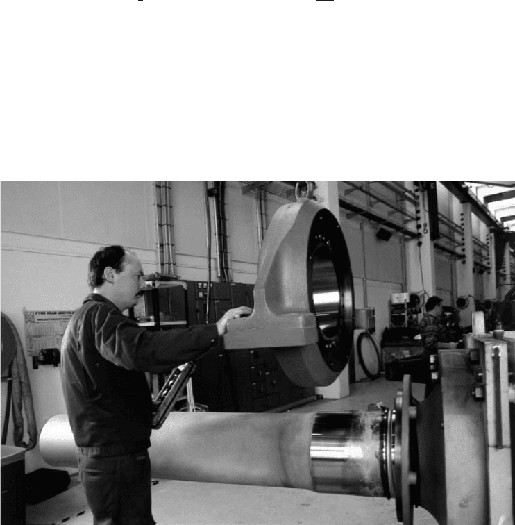
weight as it rotates. Figure 5.39 shows a low-speed shaft and front bearing in a
factory prior to assembly.
The shaft moments due to out-of-plane loads on the blades can be expressed as
moments about a pair of rotating axes, one perpendicular to blade 1 and the other
parallel to it. In the case of a three-bladed rotor, these moments are respectively as
follows:
M
YS
¼ ˜M
Y1
1
2
(˜M
Y2
þ ˜M
Y3
) M
ZS
¼
ffiffiffi
3
p
2
(˜M
Y3
˜M
Y2
)(5:118)
Here ˜ M
Y1
, ˜ M
Y2
and ˜ M
Y3
are the fluctuations of the blade out-of-plane moments
about the hub centre (M
Y1
, M
Y2
and M
Y3
) about the mean value (see Figure 5.40).
5.10.2 Deterministic aerodynamic loads
The deterministic aerodynamic loads on the rotor may be split up into a steady
component, equal for each blade, and a periodic component, also equal for each
Figure 5.39 Low-speed Shaft and Front Bearing Before Assembly. The hub mounting flange
at the right-hand end is bolted to a temporary support to allow the bearing to be threaded on
the shaft. (Reproduced by permission of NEG Micon)
294
DESIGN LOADS FOR HORIZONTAL-AXIS WIND TURBINES
