Braibant S., Giacomelli G., Spurio M. Particles and Fundamental Interactions: An Introduction to Particle Physics
Подождите немного. Документ загружается.


9.6 LEP Experiments and Examples of Events at LEP 239
Perl (Nobel laureate in 1995) and colleagues at the SPEAR colliding ring of
SLAC. The magnetic apparatus detected and distinguished between leptons, hadrons
and photons.
C
pairs were produced through the reaction: e
C
e
! !
C
.The
cross-section .e
C
e
!
C
/ is zero for
p
s < 3;700 MeV; for
p
s>
3;700 MeV, the cross-section increases rapidly until it reaches the same value of
.e
C
e
!
C
/ and then it follows the same trend with increasing energy.
The equality of the cross-sections .e
C
e
! e
C
e
/ D .e
C
e
!
C
/ D
.e
C
e
!
C
/ at high energies represents a test of the lepton universality:the
three leptons e
;
;
behave in a similar way.
The lepton has a short lifetime,
D 2:96 10
13
s. In the first experiments
performed at c.m. energies around 4 GeV, the were only observed through their
decay products. Amongst these decays, the leptonic decay channels are easily
identified; these leptonic decay modes are:
!
e
e
,
!
, each
with a branching ratio of 18% (in about 64% of the case, the decays in charged
hadrons, plus the tau neutrino). The leptonic decays of
C
pairs give rise to
e
C
e
;
C
pairs and to e
C
or e
C
combinations. The has been discovered
through the observation of e
˙
in acoplanar configuration. These final states seem
to produce an apparent violation of the conservation of the electron and muon lepton
numbers (there is in fact no such violation because neutrinos and antineutrinos
carrying the right lepton number are present in the final states in order to insure
the conservation).
The tau neutrino is the most recently discovered particle in the Standard Model.
It was first reported by the DONUT experiment at the Fermilab in July 2000.
9.6 LEP Experiments and Examples of Events at LEP
9.6.1 The LEP Detectors
At the LEP collider [9B00] at CERN, Sect. 3.3.1, in operation from 1989 until 2000,
data were collected by four large detectors: ALEPH, DELPHI, L3 and OPAL. These
detectors had a cylindrical structure, with dimensions of at least '10 m in diameter,
'10 m in length. They consisted a set of subdetectors, most of them arranged
in a concentric cylindrical structure with the axis coincident with the LEP beam
pipe. The detectors were closed on each side by two end-caps. These multipurpose
devices were able to detect, in any direction, any type of particle produced (except
neutrinos) at the e
C
e
interaction point. Experiments of this type are sometimes
called 4 detectors because they are able to detect particles emitted in almost the
full solid angle. Figure 9.5 shows the general characteristics of a LEP detector.
The main features of the four LEP detectors are summarized in Table 9.3.Since
the LEP detectors had a similar structure, we shall hereafter use the OPAL detector
as an example.
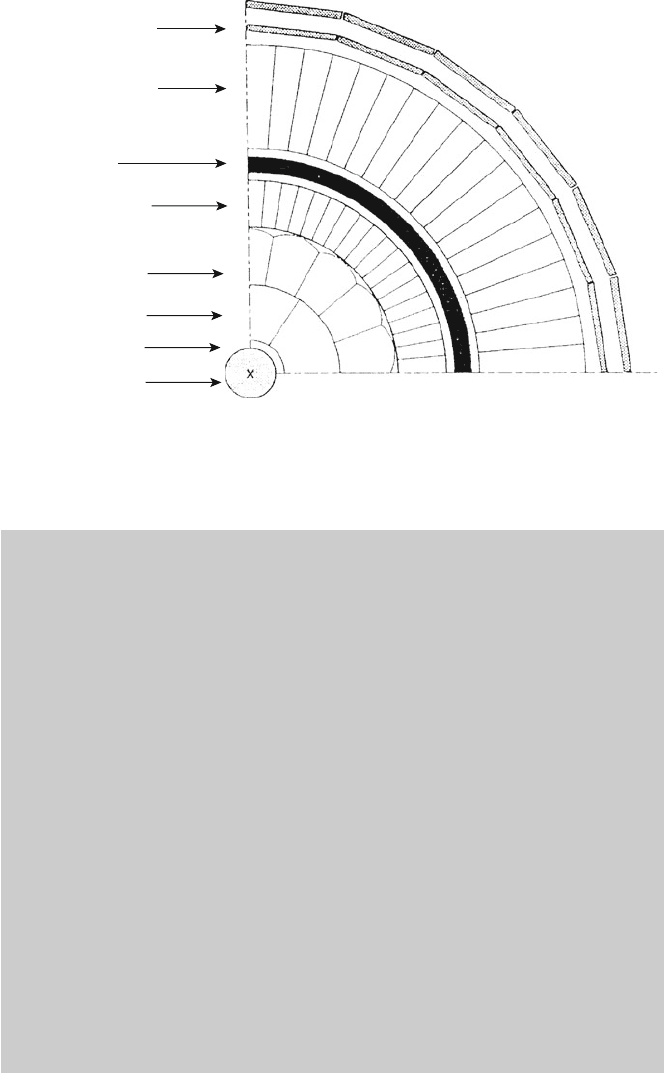
240 9 Discoveries in Electron-Positron Collisions
Muon detector
Hadronic calorimeter
and iron yoke
Solenoid
Electromagnetic
calorimeter
Particle
identification
Charged particle
tracker
Micro-vertex
Vacuum pipe
Interaction point
Fig. 9.5 Transverse view of an idealized LEP detector. The subdetector designed for particle
identification is only present in some experiments (for example, the DELPHI Cherenkov detector)
The OPAL detector. The central detector consisted of a system of tracking
chambers providing charged particle reconstruction over 96% of the full
solid angle inside a 0.435 T uniform magnetic field. It consisted of a two-
layer silicon microstrip vertex detector, a high-precision drift chamber, a
large-volume JET chamber and a set of z-chambers measuring the track
coordinates along the beam direction. The Central Jet chamber not only
improved the measurement of the trajectory of the charged particles, but
had an important role in particle identification by measuring the specific
energy loss through ionization. The central tracking devices (except for the
silicon detector) were enclosed in a cylindrical pressure vessel around which
an aluminum conductor (solenoid) was wrapped; with a 7,000 A current
passing through it, the solenoid generated the required magnetic field. The
magnetic field was oriented along the axial direction and caused the charged
particles to bend on a helical path around the magnetic field direction.
The curvature of the track of the charged particle in the magnetic field
was measured, making it possible to calculate the momentum of the tracked
particle. A 1 m thick iron yoke was incorporated into the hadron calorimeter
to provide magnetic flux return. The iron yoke served as the mechanical
structure supporting the experimental apparatus. It was segmented into 10 cm
thick iron layers used as a passive element for the hadron calorimeter. The
electromagnetic calorimeter, segmented in more than ten thousand lead-glass
9.6 LEP Experiments and Examples of Events at LEP 241
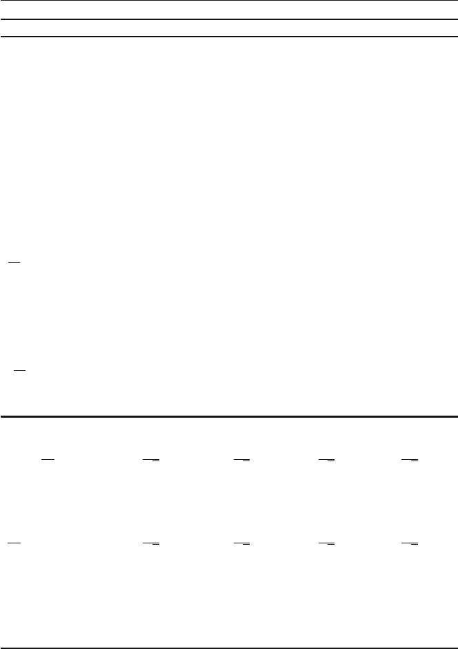
Table 9.3 Comparison of the main features of some subdetectors of the four experiments at
LEP. Precision of the radial alignment of OPAL luminometer elements: .
r
/
absolute
' 200 m,
.
r
/
relative
' 10 m
+Sub–detector
Detector)
OPAL L3 ALEPH DELPHI
Tracker
Microvertex
Resolutions [m]
.r;'/
57128
z
15 14 10
(for normal incidence)
Vertex chamber
External diameter [mm] ˛D235 ˛D180 ˛D288
Length L [m] 1 1 2
Resolutions
.r;'/
[m] 50 45 150 <150
Central chamber JET TEC TPC TPC
External diameter [m] ˛D3:8 ˛D0:9 ˛D3:6 ˛D1:2
Length [m] L D 4.5 L D 1LD 4.8 L D 2.8
Resolutions [m]
.r;'/
D 135
.r;'/
D 45
.r;'/
D 150
.r;'/
D 250
Resolution
on track momentum
p
p
2
10
3
.GeV/c/
1
1.1 0.6 0.7
Obtained with
JET
TP C
CVTX
TP C
CVTX
z-chamber [m]
z
D 300
dE=dx (0.5 GeV/c )3.2%
detection (barrel)
Resolution
on muon momentum
h
p
p
%
i
45 GeV
5.5 2.5 3.0 3.5
r'
[mm] ;
[mr] 1.5 ; 5
Calorimeters
Electromagnetic LGB BGO PWT HPC
11,704 blocks 7,680 blocks
Energy
resolution
h
E
E
%
i
45 GeV
6:3
p
E
˚ 0:2
2
p
E
˚ 0:9
19:5
p
E
˚1
26
p
E
˚ 4
Spatial
resolution
[.r; '/ ; #] 2:3
ı
I2:3
ı
2:3
ı
I2; 3
ı
1
ı
I1
ı
1
ı
I0:1
ı
[cm] 1 1 3 9
Hadronic
h
E
E
%
i
45 GeV
120
p
E
55
p
E
˚ 5
100
p
E
120
p
E
Spatial
resolution
[.r; '/; #] 7
ı
I7
ı
2:5
ı
I2:5
ı
3:7
ı
I3:7
ı
3
ı
I4
ı
Barrel diameter [m] '10 16 '10 '10
Barrel length [m] 10 10 12 10
Magnetic field [T] 0.43 0.4 2 1
Time of flight [ns] 0.2
TEC time expansion chamber, TPC time projection chamber, LGB lead glass block, BGO bismuth
germanium oxide, PWT proportional wire tube, HPC high density projection chamber, RICH ring
imaging CHerenkov, JET JET-CHamber, VTX VerTeX (vertex detectors), PRES PRE-Sampler

242 9 Discoveries in Electron-Positron Collisions
blocks, was installed in the space located between the solenoid and the
magnetic yoke. It was used for the identification and energy measurement of
photons, electrons and positrons.
In addition to the subdetectors described above, the OPAL detector
included others that will now be briefly described, starting from the innermost
device and proceeding to the outermost one.
The first subdetector was located at the interaction point and immediately
surrounding the vacuum pipe where the e
C
and e
beams were circulating.
It was a solid state silicon microvertex detector designed to give precise
measurements regarding the position of the charged particle tracks. The
accuracy of this detector allowed for the measurements with a resolution of
the order of a few microns on the position of any secondary vertices resulting
from decays of unstable particles produced in the primary e
C
e
interaction.
The microvertex detector was the first subdetector of the OPAL tracking
system that allowed the detection of electrically charged particles produced
at the e
C
e
interaction point. The second subdetector surrounding the
microvertex detector was a set of high precision drift chambers, the vertex
chambers. Just outside the vertex chambers, one had the large-volume JET
chamber, followed by a set of drift chambers called the z-chambers designed
to precisely measure the position of the tracks along the axial direction of the
beams (z axis).
The central tracking system was enclosed in the solenoid that produced the
magnetic field directed along the z axis. The Time-of-Flight (TOF) detector
was installed on the outer surface of the solenoid. It was made of scintillation
counters and designed to measure the transit time of particles traveling from
the interaction region with a time resolution of about 0.4 ns.
The next detector was the electromagnetic calorimeter consisting of a
presampler made of thin chambers arranged around the TOF, and the main
calorimeter formed of lead-glass blocks. The electromagnetic calorimeter was
composed of a central “barrel” and of two “end-caps.”
The following detector was the hadron calorimeter which served for the
energy measurement of all hadrons produced in the e
C
e
collisions. This
detector was a sampling calorimeter using limited streamer tubes as active
elements interleaved with the magnet yoke iron layers as passive absorbing
material. This detector was also used to track muons passing through it.
The outermost detector was the muon detector used to identify and track
muons with energies above 3 GeV; indeed, only such muons managed to cross
the entire thickness of the apparatus and be detected by the four layers of drift
chambers mounted on the external surface of the magnetic yoke.
To determine the cross-section of each reaction considered, it was nec-
essary to precisely measure the LEP luminosity in the OPAL interaction
point. This was done by measuring the frequency of elastic positron-electron
collisions in a small angular region at small angles, where the cross-section

9.6 LEP Experiments and Examples of Events at LEP 243
is large and can be calculated with great precision. The detector used
for measuring the elastic scattering at small angles was composed of two
electromagnetic calorimeters mounted immediately around the beam pipe,
both on the right and the left sides of the collision. Each of them was formed
of two parts; the first one was made of silicon sensitive elements and tungsten
absorbers. It covered a region at small angles and was called the lumi-
nometer. The second part was composed of scintillators as active elements
plus passive lead absorbers; this part was called the forward detector. The
luminometer allowed a luminosity measurement with a precision better than
one per mil. This was very important for the precision measurements of the
Z
0
boson parameters.
The choice of the various subdetectors was of course guided by consider-
ations based on the LEP research programs.
9.6.2 Events in 4 Detectors at LEP
In the following, we shall discuss a few simple events observed with the OPAL
detector. These events are interesting from an educational point of view in order to
understand the techniques that were used as well as to illustrate various aspects of
particle physics.
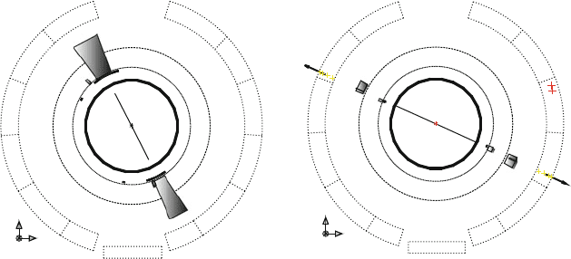
An elastic event. Figure 9.6a shows the “event display” of an e
C
e
! e
C
e
elastic
collision. The positron and the electron beams are perpendicular to the page; they
collide at the interaction point and are scattered. In the central detector, two tracks
emitted in opposite directions are observed. Each track results from the combination
of 18 positions (points) measured in the vertex chamber, 159 points in the JET
chamber and six points in the z-chamber. The tracks, each 45.6GeV, are slightly
curved due to the 0.435 T magnetic field. The curvature can only be observed at a
larger magnification. The curvature would be larger in the ALEPH and DELPHI
detectors which had higher magnetic fields (respectively 2 and 1 T).
Inside the electromagnetic calorimeter, the electron and the positron each
generate an electromagnetic shower. The graphic representation shown in Fig. 9.6a
is a shaded trapezoid; it represents the analogue signal observed in each of the
lead-glass blocks hit by the particles. The signal has a base equal to the size of a
lead-glass block (10 cm) and a height proportional to the deposited energy (in this
case 45.6 GeV per side).
This elastic event is a simple event, mainly characterized by the release of all the
energy in two diametrically opposite sectors of the electromagnetic calorimeter. No
signal is detected in the hadron calorimeter and in the muon detector, which is the
evidence that the final state only contains one positron and one electron, each with
an energy equal to that of the incident particles.
244 9 Discoveries in Electron-Positron Collisions
y
x
z
ab
.
y
x
z
Fig. 9.6 (a) Transverse view of an elastic event e
C
e
! e
C
e
observed in the OPAL detector.
The final state electron and positron are detected in the central tracking detector, the time-of-
flight system and in the electromagnetic calorimeter. In the latter one, the electron and the positron
release a large energy represented by two large gray shaded trapezoids.(b) Interaction e
C
e
!
C
:the
C
and the
are detected in the central tracking detector, the time-of-flight system,
the electromagnetic calorimeter, the hadronic calorimeter (gray rectangles on each side) and in the
muon detector (arrows on each side). The z axis is perpendicular to the page with its direction
pointing out. The magnetic field is oriented along the z axis
The selection of these events is mainly based on the presence of an electronic
signal into two diametrically opposite counters of the electromagnetic calorimeter,
with the additional condition that each signal has an energy at least equal to half of
that of each incident electron or positron. The number of elastic events, excluding
the region of small angles, represents 3.3% of the total number of observable events.
The reaction e
C
e
! gives rise to only two signals in opposite sectors of
the electromagnetic calorimeter since the photons are electrically neutral and do not
leave any signal in the tracking chambers.
Interaction e
C
e
!
C
. Figure 9.6b shows an event due to an interaction
e
C
e
!
C
. The two muons are represented by the two tracks, emitted in
opposite directions in the central tracking detector and by the two small signals,
also diametrically opposite, in the time-of-flight system. Thus far, there are no
differences with respect to the elastic collision shown in Fig. 9.6a. The differences
concern the signals deposited in the electromagnetic calorimeter. The presence of
two very small gray trapezoids, diametrically opposite, indicates that the energy
released by each muon in a lead-glass block is about 0.2 GeV.
The next detector hit by the muons is the hadronic calorimeter. The analogue
signals recorded by its “tower structure” are illustrated by two small “towers;” the
passage of a single muon that does not interact along its path produces relatively
small signals. In the muon detector, the passage of two charged particles in the
muon chamber is represented by arrows in opposite sectors. Such signals are due
9.6 LEP Experiments and Examples of Events at LEP 245
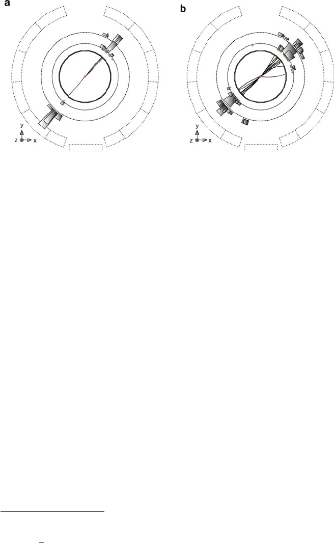
Fig. 9.7 (a) Interaction e
C
e
!
C
in the OPAL detector. (b) Interaction e
C
e
! two
particle jets (hadrons). The decay products are observed in the central tracking detector, the
electromagnetic calorimeter and in the hadronic calorimeter
to particles that are able to cross the whole detector, including more than a meter
of iron. Therefore, with no doubt, these two particles are muons. As for the elastic
events,
C
pairs are produced at the 3.3% level of the total observable events.
Interaction e
C
e
!
C
(Fig. 9.7a). The lepton is unstable and decays with a
lifetime of 0:310
12
s, corresponding to a mean decay length (distance between the
production and decay points) of a few mm
2
. Therefore, the decay occurs inside the
LEP vacuum pipe and only the decay products are observed in the detector. Using
the information provided by the silicon microvertex detector and the vertex chamber,
charged particle tracks coming from secondary vertices can be reconstructed and the
lepton lifetime can be measured.
In Fig. 9.7a, the
C
(track at the bottom left) decays in
C
!
C
N
. A track
is observed in the central tracking detector as well as a clear signal in the hadronic
calorimeter (gray towers). The pion decays roughly in the same direction as the
tau. The
(track at the top right) decays in
!
C
. Due to the high
energy of the
, the three pions produce a jet of three charged particles propagating
approximately along the initial direction of the
. No signal is observed in the
muon detector because the final state charged particles are hadrons and the neutral
ones are neutrinos (which almost do not interact).
As for the two previous cases, the
C
events amount for 3.3% of the total
observable events. The equal production of e
C
e
,
C
,
C
is representative of
the “lepton universality.” It is also quite significant that no heavier charged leptons
are observed.
2
The decay length L is given by L D ˇc where ˇ D p=m, c is the speed of light and is the
lifetime of the considered particle. With p ' 45 GeV, m
=1.7GeVand
D 300 10
15
s, one
finds L D
p
m
c
= 2.5 mm.
246 9 Discoveries in Electron-Positron Collisions
q
q
–
θ
hadrons
hadrons
e
+
e
–
e
+
e
–
g
θ
hadrons
hadrons
hadrons
ab
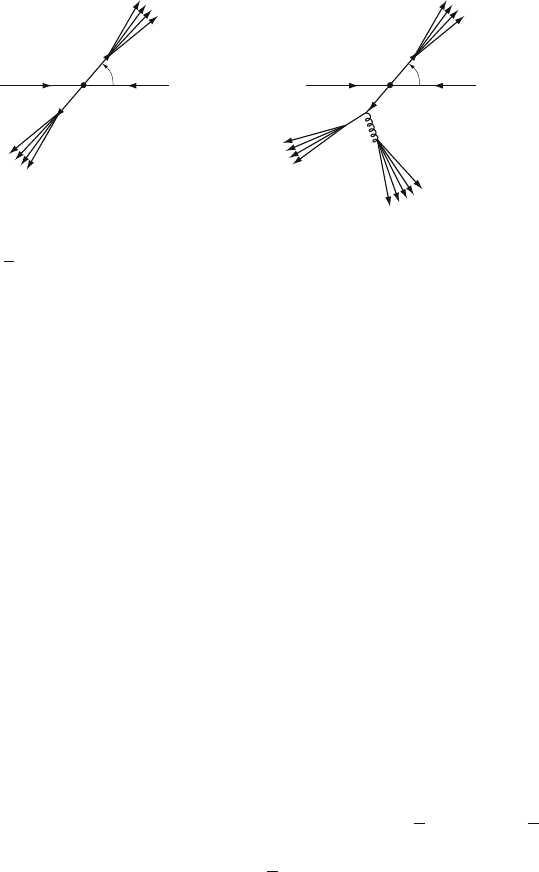
Fig. 9.8 Illustration of the formation process of two or more hadronic jets. The primary interaction
is e
C
e
! qq. It is followed by (a) the quark and antiquark hadronization which gives rise to
two hadronic jets emitted in opposite directions; (b) if the quark (or the antiquark) radiates a gluon
g, three jets are present in the final state
Interaction e
C
e
!hadronic jets. Figure 9.7b illustrates the interaction e
C
e
!
two hadronic jets (diametrically opposite). In the central detector, each jet is made
of various charged tracks emitted in a rather small solid angle. The tracks are
considerably bent by the magnetic field. Note that the jets contain tracks due to
particles both with negative or positive electric charge.
In the time-of-flight system and in the electromagnetic calorimeter, each jet of
hadrons hits a number of counters. The overall energy released in the electromag-
netic calorimeter is about 15 GeV per jet, a fraction is due to neutral particles that
are unobserved in the central detector. In the hadronic calorimeter, each jet releases
(10–15)GeV and produces a series of gray towers. These are typical signals for a
hadronic shower which is concentrated in the first half of the calorimeter.
No signal is recorded in the muon detector, confirming the nature of the two
hadronic jets of particles. The main characteristics of the two jets are: (1) they are
emitted in diametrically opposite directions, (2) each jet deposits a high energy and
there are strong indications in favor of the hadronic nature of the particles of the two
jets, (3) each jet is contained in a cone with a small aperture angle.
These considerations suggest that the jet production does not result from direct
electron-positron collisions, but rather that the process occurs in two steps: the
incident electron and positron produce a quark-antiquarkpair, each quark giving rise
to a hadronic jet (each quark “hadronizes” in a jet): e
C
e
! qq, q ! jet 1; q !
jet 2: The jets become more and more collimated with increasing c.m. energy: in
this way, it is possible to determine the q and
q flight directions.
The processes involved in the jet production are illustrated in Fig.9.8a. Two jet
events are experimental evidence in favor of quark existence. Further confirmations
come from more detailed analyses; these statistical studies also allow one to identify
the type of quark involved and to measure its fractional charge. Events with
two hadronic jets in the final state represent the majority of observable events,
about 70%.
9.6 LEP Experiments and Examples of Events at LEP 247
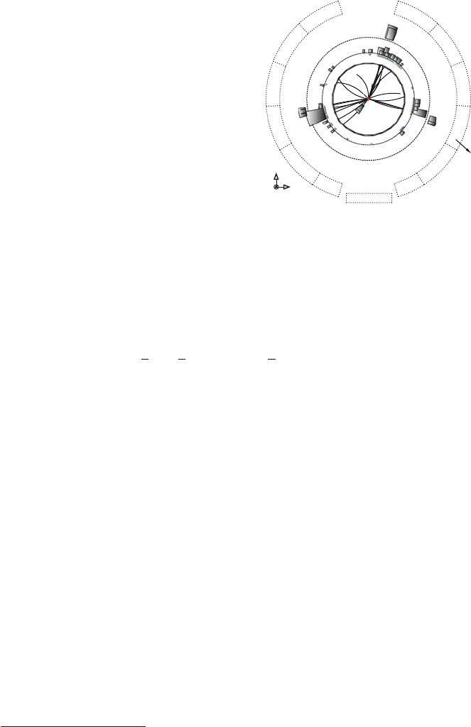
Fig. 9.9 An OPAL event
with three jets of particles in
the final state. The three jets
are represented as three
groups of tracks in the central
detector and as rectangles in
the electromagnetic
calorimeter. The third jet of
particles is due to the
radiation of a gluon by the
quark or antiquark
y
x
z
Interaction e
C
e
! 3 hadronic jets:
3
Figure 9.9 shows an inelastic interaction
e
C
e
! 3 hadronic jets. The tracks in the central detector are grouped into three
jets.
To interpret three jet events, one must take into account the gluons, i.e., the
bosons that mediate the strong interaction. The quark (or the antiquark) can radiate
a gluon which also produces a jet of particles (Fig. 9.8b):
e
C
e
! qq ! qqg; q ! jet 1; q ! jet 2; g ! jet 3:
The existence of multihadronic events with three jets in the final state was the first
experimental evidence for the existence of gluons. The emission of a gluon by a
quark is similar to “bremsstrahlung” radiation.
The gluon has usually low energy and produces a less energetic and not well
defined jet (sometimes too small to be detectable). The gluon energy distribution
has characteristics similar to that of bremsstrahlung photons. There are many low
energy gluons. The number of observable jets is connected to the resolution of the
apparatus and to the used jet reconstruction algorithm. Typically, the number of
events with three well separated hadronic jets is about 15% of the total number of
hadronic events. The ratio between the number of three jet events and that of two jet
events provides information on the coupling of a gluon to a quark, and depends on
the dimensionless “strong” coupling constant ˛
s
.
Events with four or more jets were also observed; they are interpreted as being
due to the radiation of two or more gluons and the subsequent quark and gluon
hadronization.
3
These events were first observed by the TASSO experiment at the PETRA accelerator at the DESY
laboratory.

248 9 Discoveries in Electron-Positron Collisions
9.7 e
C
e
Collisions at E
cm
91 GeV. The Z
0
Boson
In the following, we shall discuss the e
C
e
collisions at energies close to the Z
0
peak. A brief description of the formulas needed to explain the Z
0
physics, together
with the experimental results, will be presented. The main physics results obtained
in e
C
e
collisions at
p
s ' 91 GeV can be summarized as follows:
• The determination of the number of light neutrino families (three) and therefore
of the number of families of quarks and leptons
• The precise determination of the Z
0
parameters and of various electroweak
quantities and the determination below threshold of the t quark mass
• The demonstration that the strong coupling constant ˛
s
decreases with increasing
energy (“running”) and that it is independent of the quark flavor
• The verification that also ˛
EM
increases with energy
• Systematic studies of the properties of the hadronic jets, in particular: the
differences between jets initiated by quarks and jets initiated by gluons; the first
evidence for the 4-gluon vertex; the demonstration that the theory of the strong
interaction is nonabelian; the ln s dependence of the number of hadrons produced
• The spectroscopy of hadrons with quark b
• Precise measurements of the lifetimes of hadrons with quark c; b and of the
lepton
• The determination of stringent limits on new particles, rare decays and on the
Higgs (H
0
) boson mass
9.7.1 The Z
0
Resonance
The measurement of the e
C
e
!Z
0
/ ! f
N
f cross-section as a function of the c.m.
energy allows one to measure the Z
0
parameters such as its mass m
0
Z
and total width
Z
. The cross-section can be computed by considering the diagrams of Fig.9.2.For
each final state f
N
f , there are three different contributions:
• A term due to the electromagnetic interaction e
C
e
! ! f
N
f .Thisisthe
dominant contribution for c.m. energy below the Z
0
mass. The EM term has a
1=s dependence typical of the electromagnetic annihilation
• A term due to the weak interaction e
C
e
! Z
0
! f
N
f . This contribution
dominates at the Z
0
resonance,
p
s D m
Z
0
, the so-called “Z
0
peak”
• An EM/weak interference term vanishing at the Z
0
resonance
At the “Z
0
peak,” the production of “real” (on mass shell) Z
0
can be studied.
This means that in the diagram of Fig. 9.2b, the Z
0
is produced with energy and
momentum such that E
2
p
2
D m
2
Z
.
Let us analyze in more detail the behavior of the cross-section around the Z
0
peak
(omitting the purely electromagnetic term and terms due to radiative corrections).