Bird J. Electrical Circuit Theory and Technology
Подождите немного. Документ загружается.


186 Electrical Circuit Theory and Technology
Figure 13.45
Thus Figure 13.45(b) shows a network equivalent to Figure 13.45(a).
From Figure 13.45(b) the total short-circuit current is 4 C12 D 16 A
and the total resistance is given by:
3 ð 2
3 C 2
D 1.2
Thus Figure 13.45(b) simplifies to Figure 13.45(c).
The open-circuit voltage across AB of Figure 13.45(c),
E D 161.2 D 19.2 V, and the resistance ‘looking-in’ at AB is
1.2 . Hence the Th
´
evenin equivalent circuit is as shown in
Figure 13.45(d).
(b) When the 1.8 resistance is connected between terminals A and B
of Figure 13.45(d) the current I flowing is given by:
I D
19.2
1.2 C1.8
D 6.4A
Problem 19. Determine by successive conversions between
Th
´
evenin and Norton equivalent networks a Th
´
evenin equivalent
circuit for terminals AB of Figure 13.46(a). Hence determine the
current flowing in the 200 resistance.
Figure 13.46

D.c. circuit theory 187
For the branch containing the 10 V source, converting to a Norton equiv-
alent network gives
I
SC
D
10
2000
D 5mAandr
1
D 2k.
For the branch containing th
e 6 V source, converting to a Norton equiv-
alent network gives
I
SC
D
6
3000
D 2mAandr
2
D 3k.
Thus the network of Figure 13.46(a) converts to Figure 13.46(b).
Combining the 5 mA and 2 mA current sources gives the equivalent
network of Figure 13.46(c) where the short-circuit current for the original
two branches considered is 7 mA and the resistance is
2 ð 3
2 C 3
D 1.2k.
Both of the Norton equivalent networks shown in Figure 13.46(c) may
be converted to Th
´
evenin equivalent circuits. The open-circuit voltage
across CD is (7 ð10
3
)(1.2 ð 10
3
D 8.4 V and the resistance ‘looking-
in’ at CD is 1.2k.
The open-circuit voltage across EF is 1 ð 10
3
600 D 0.6 V and the
resistance ‘looking-in’ at EF is 0.6 k. Thus Figure 13.46(c) converts to
Figure 13.46(d). Combining the two Th
´
evenin circuits gives
E D 8.4 0.6 D 7.8Vand the resistance
r D 1.2 C0.6 k D 1.8kZ.
Thus the Th
´
evenin equivalent circuit for terminals AB of Figure 13.46(a)
is as shown in Figure 13.46(e).
Hence the current I flowing in a 200 resistance connected between A
and B is given by:
I D
7.8
1800 C 200
D
7.8
2000
D 3.9mA
Further problems on Norton’s theorem may be found in Section 13.10,
problems 16 to 21, page 191.
13.9 Maximum power
transfer theorem
The maximum power transfer theorem states:
‘The power transferred from a supply source to a load is at its maximum
when the resistance of the load is equal to the internal resistance of the
source.’
Figure 13.47
Hence, in Figure 13.47, when R D r the power transferred from the source
to the load is a maximum.

188 Electrical Circuit Theory and Technology
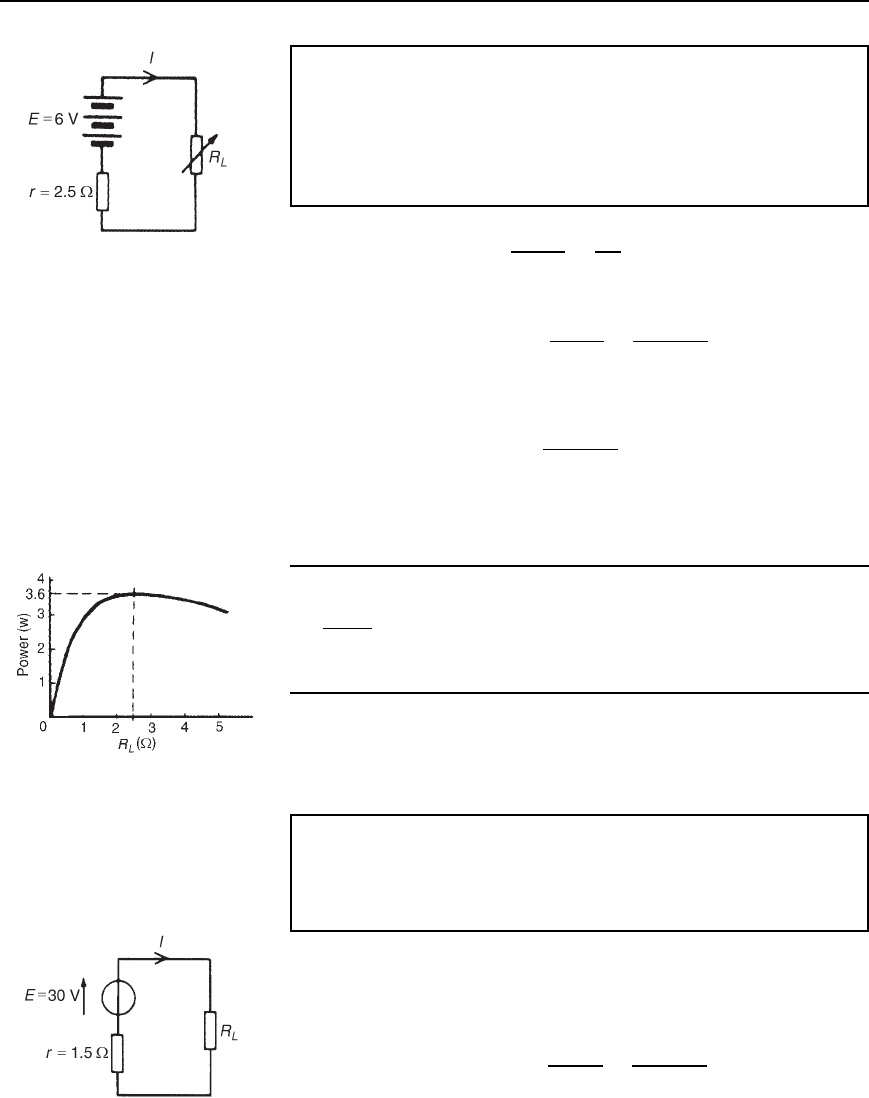
Figure 13.48
Problem 20. The circuit diagram of Figure 13.48 shows dry cells
of source e.m.f. 6 V, and internal resistance 2.5. If the load resis-
tance R
L
is varied from 0 to 5 in 0.5 steps, calculate the power
dissipated by the load in each case. Plot a graph of R
L
(horizon-
tally) against power (vertically) and determine the maximum power
dissipated.
When R
L
D 0, current I D
E
r C R
L
D
6
2.5
D 2.4 A and power dissipated
in R
L
,PD I
2
R
L
,i.e.P D 2.4
2
0 D 0W
When R
L
D 0.5 , current I D
E
r C R
L
D
6
2.5 C0.5
D 2A
and P D I
2
R
L
D 2
2
0.5 D 2W
When R
L
D 1.0, current I D
6
2.5 C1.0
D 1.714 A
and P D 1.714
2
1.0 D 2.94 W
With similar calculations the following table is produced:
R
L
0 0.5 1.0 1.5 2.0 2.5 3.0 3.5 4.0 4.5 5.0
I D
E
r C R
L
2.4 2.0 1.714 1.5 1.333 1.2 1.091 1.0 0.923 0.857 0.8
P D I
2
R
L
W 0 2.00 2.94 3.38 3.56 3.60 3.57 3.50 3.41 3.31 3.20
A graph of R
L
against P is shown in Figure 13.49. The maximum value
of power is 3.60 W which occurs when R
L
is 2.5 ,i.e.maximum
power occurs when R
L
= r, which is what the maximum power transfer
theorem states.
Figure 13.49
Problem 21. A d.c. source has an open-circuit voltage of 30 V and
an internal resistance of 1.5 . State the value of load resistance
that gives maximum power dissipation and determine the value of
this power.
The circuit diagram is shown in Figure 13.50. From the maximum
power transfer theorem, for maximum power dissipation,
R
L
D r D 1.5 Z
From Figure 13.50, current I D
E
r C R
L
D
30
1.5 C1.5
D 10 A
Power P D I
2
R
L
D 10
2
1.5 D 150 W D maximum power dissipated
Figure 13.50

D.c. circuit theory 189
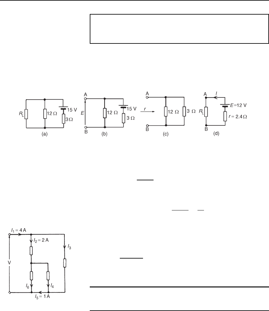
Problem 22. Find the value of the load resistor R
L
shown in
Figure 13.51(a) that gives maximum power dissipation and deter-
mine the value of this power.
Using the procedure for Th
´
evenin’s theorem:
(i) Resistance R
L
is removed from the circuit as shown in
Figure 13.51(b).
Figure 13.51
(ii) The p.d. across AB is the same as the p.d. across the 12 resistor.
Hence E D
12
12 C 3
15 D 12 V
(iii) Removing the source of e.m.f. gives the circuit of Figure 13.51(c),
from which resistance, r D
12 ð 3
12 C3
D
36
15
D 2.4
(iv) The equivalent Th
´
evenin’s circuit supplying terminals AB is shown
in Figure 13.51(d), from which, current, I D E/r C R
L
For maximum power, R
L
D r D 2.4 Z. Thus current,
I D
12
2.4 C2.4
D 2.5A.
Power, P, dissipated in load R
L
, P D I
2
R
L
D 2.5
2
2.4 D 15 W
Further problems on the maximum power transfer theorem may be found
in Section 13.10 following, problems 22 and 23, page 192.
Figure 13.52
13.10 Further problems
on d.c. circuit theory
Kirchhoff’s laws
1 Find currents I
3
, I
4
and I
6
in Figure 13.52
[I
3
D 2A;I
4
D1A;I
6
D 3A]

190 Electrical Circuit Theory and Technology
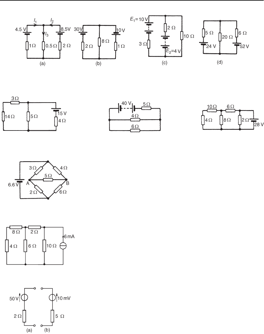
Figure 13.53
2 For the networks shown in Figure 13.53, find the values of the currents
marked.
[(a) I
1
D 4A,I
2
D1A,I
3
D 13 A
(b) I
1
D 40 A,I
2
D 60 A,I
3
D 120 A,
I
4
D 100 A,I
5
D80 A]
3 Use Kirchhoff’s laws to find the current flowing in the 6 resistor
of Figure 13.54 and the power dissipated in the 4 resistor.
[2.162 A, 42.07 W]
4 Find the current flowing in the 3 resistor for the network shown in
Figure 13.55(a). Find also the p.d. across the 10 and 2 resistors.
[2.715 A, 7.410 V, 3.948 V]
5 For the networks shown in Figure 13.55(b) find: (a) the current in the
battery, (b) the current in the 300 resistor, (c) the current in the
90 resistor, and (d) the power dissipated in the 150 resistor.
[(a) 60.38 mA(b) 15.10 mA
(c) 45.28 mA(d) 34.20 mW]
6 For the bridge network shown in Figure 13.55(c), find the currents I
1
to I
5
.
[I
1
D 1.26 A,I
2
D 0.74 A,I
3
D 0.16 A
I
4
D 1.42 A,I
5
D 0.59 A]
Figure 13.54
Superposition theorem
7 Use the superposition theorem to find currents I
1
, I
2
and I
3
of
Figure 13.56(a). [I
1
D 2A,I
2
D 3A,I
3
D 5A]
8 Use the superposition theorem to find the current in the 8 resistor
of Figure 13.56(b). [0.385 A]
9 Use the superposition theorem to find the current in each branch of
the network shown in Figure 13.56(c).
[10 V battery discharges at 1.429 A
4 V battery charges at 0.857 A
Current through 10 resistor is 0.572 A]
10 Use the superposition theorem to determine the current in each
branch of the arrangement shown in Figure 13.56(d).
[24 V battery charges at 1.664 A
52 V battery discharges at 3.280 A
Current in 20 resistor is 1.616 A]
Th
´
evenin’s theorem
11 Use Th
´
evenin’s theorem to find the current flowing in the 14
resistor of the network shown in Figure 13.57. Find also the power
dissipated in the 14 resistor. [0.434 A, 2.64 W]
Figure 13.55

D.c. circuit theory 191
Figure 13.56
Figure 13.57 Figure 13.58 Figure 13.59
12 Use Th
´
evenin’s theorem to find the current flowing in the 6
resistor shown in Figure 13.58 and the power dissipated in the 4
resistor. [2.162 A, 42.07 W]
13 Repeat problems 7–10 using Th
´
evenin’s theorem.
14 In the network shown in Figure 13.59, the battery has negligible
internal resistance. Find, using Th
´
evenin’s theorem, the current
flowing in the 4 resistor. [0.918 A]
15 For the bridge network shown in Figure 13.60, find the current in
the 5 resistor, and its direction, by using Th
´
evenin’s theorem.
[0.153 A from B to A]
Figure 13.60
Norton’s theorem
16 Repeat problems 7–12, 14 and 15 using Norton’s theorem.
17 Determine the current flowing in the 6 resistance of the network
shown in Figure 13.61 by using Norton’s theorem. [2.5 mA]
Figure 13.61
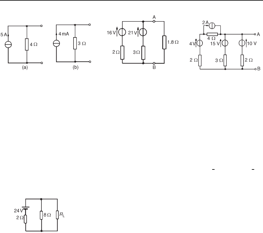
18 Convert the circuits shown in Figure 13.62 to Norton equivalent
networks.
[(a) I
SC
D 25 A,r D 2
(b) I
SC
D 2mA,r D 5 ]
19 Convert the networks shown in Figure 13.63 to Th
´
evenin equivalent
circuits.
[(a) E D 20 V,r D 4
(b) E D 12 mV,r D 3 ]
Figure 13.62

192 Electrical Circuit Theory and Technology
Figure 13.63 Figure 13.64 Figure 13.65
20 (a) Convert the network to the left of terminals AB in Figure 13.64
to an equivalent Th
´
evenin circuit by initially converting to a
Norton equivalent network.
(b) Determine the current flowing in the 1.8 resistance connected
between A and B in Figure 13.64.
[(a) E D 18 V, r D 1.2 (b)6A]
21 Determine, by successive conversions between Th
´
evenin and Norton
equivalent networks, a Th
´
evenin equivalent circuit for terminals
AB of Figure 13.65. Hence determine the current flowing in a 6
resistor connected between A and B.
[E D 9
1
3
V, r D 1 ,1
1
3
A]
Maximum power transfer theorem
22 A d.c. source has an open-circuit voltage of 20 V and an internal
resistance of 2 . Determine the value of the load resistance that
gives maximum power dissipation. Find the value of this power.
[2 ,50W]
23 Determine the value of the load resistance R
L
shown in Figure 13.66
that gives maximum power dissipation and find the value of the
power. [R
L
D 1.6 , P D 57.6W]
Figure 13.66

14 Alternating voltages
and currents
At the end of this chapter you should be able to:
ž appreciate why a.c. is used in preference to d.c.
ž describe the principle of operation of an a.c. generator
ž distinguish between unidirectional and alternating waveforms
ž define cycle, period or periodic time T and frequency f of a
waveform
ž perform calculations involving T D
1
f
ž define instantaneous, peak, mean and rms values, and form
and peak factors for a sine wave
ž calculate mean and rms values and form and peak factors for
given waveforms
ž understand and perform calculations on the general sinusoidal
equation
v D V
m
sinωt š
ž understand lagging and leading angles
ž combine two sinusoidal waveforms (a) by plotting graphically,
(b) by drawing phasors to scale and (c) by calculation
ž understand rectification, and describe methods of obtaining
half-wave and full-wave rectification
14.1 Introduction
Electricity is produced by generators at power stations and then distributed
by a vast network of transmission lines (called the National Grid system)
to industry and for domestic use. It is easier and cheaper to generate
alternating current (a.c.) than direct current (d.c.) and a.c. is more conve-
niently distributed than d.c. since its voltage can be readily altered using
transformers. Whenever d.c. is needed in preference to a.c., devices called
rectifiers are used for conversion (see Section 14.7).
14.2 The a.c. generator
Let a single turn coil be free to rotate at constant angular velocity symmet-
rically between the poles of a magnet system as shown in Figure 14.1.
An e.m.f. is generated in the coil (from Faraday’s Laws) which varies
in magnitude and reverses its direction at regular intervals. The reason for
this is shown in Figure 14.2. In positions (a), (e) and (i) the conductors

194 Electrical Circuit Theory and Technology
Figure 14.1
of the loop are effectively moving along the magnetic field, no flux is cut
and hence no e.m.f. is induced. In position (c) maximum flux is cut and
hence maximum e.m.f. is induced. In position (g), maximum flux is cut
and hence maximum e.m.f. is again induced. However, using Fleming’s
right-hand rule, the induced e.m.f. is in the opposite direction to that in
position (c) and is thus shown as E. In positions (b), (d), (f) and (h)
some flux is cut and hence some e.m.f. is induced. If all such positions
of the coil are considered, in one revolution of the coil, one cycle of
alternating e.m.f. is produced as shown. This is the principle of operation
of the ac generator (i.e. the alternator).
14.3 Waveforms
If values of quantities which vary with time t are plotted to a base of
time, the resulting graph is called a waveform. Some typical waveforms
are shown in Figure 14.3. Waveforms (a) and (b) are unidirectional
waveforms, for, although they vary considerably with time, they flow
in one direction only (i.e. they do not cross the time axis and become
negative). Waveforms (c) to (g) are called alternating waveforms since
their quantities are continually changing in direction (i.e. alternately posi-
tive and negative).
A waveform of the type shown in Figure 14.3(g) is called a sine wave.
It is the shape of the waveform of e.m.f. produced by an alternator and
thus the mains electricity supply is of ‘sinusoidal’ form.
One complete series of values is called a cycle (i.e. from O to P in
Figure 14.3(g)).
The time taken for an alternating quantity to complete one cycle is
called the period or the periodic time, T, of the waveform.
Figure 14.2
The number of cycles completed in one second is called the frequency,
f, of the supply and is measured in hertz, Hz. The standard frequency of
the electricity supply in Great Britain is 50 Hz.
Figure 14.3

Alternating voltages and currents 195
T =
1
f
or f
=
1
T
Problem 1. Determine the periodic time for frequencies of
(a) 50 Hz and (b) 20 kHz
(a) Periodic time T D
1
f
D
1
50
D 0.02sor20ms
(b) Periodic time T D
1
f
D
1
20000
D 0.000 05 s or 50 ms
Problem 2. Determine the frequencies for periodic times of
(a) 4 ms, (b) 4
µs
(a) Frequency f D
1
T
D
1
4 ð 10
3
D
1000
4
D 250 Hz
(b) Frequency f D
1
T
D
1
4 ð 10
6
D
1000000
4
D 250 000 Hz or 250 kHz or 0.25 MHz
Problem 3. An alternating current completes 5 cycles in 8 ms.
What is its frequency?
Time for 1 cycle D
8
5
ms D 1.6msD periodic time T
Frequency f D
1
T
D
1
1.6 ð 10
3
D
1000
1.6
D
10000
16
D 625 Hz
Further problems on frequency and periodic time may be found in
Section 14.8, problems 1 to 3, page 209.
14.4 A.c. values
Instantaneous values are the values of the alternating quantities at any
instant of time. They are represented by small letters, i,
v, e etc., (see
Figures 14.3(f) and (g)).
The largest value reached in a half cycle is called the peak value or the
maximum value or the crest value or the amplitude of the waveform.
Such values are represented by V
m
, I
m
, etc. (see Figures 14.3(f) and (g)).
A peak-to-peak value of e.m.f. is shown in Figure 14.3(g) and is the
difference between the maximum and minimum values in a cycle.
