Biermann Ch. Handbook of Pulping and Papermaking
Подождите немного. Документ загружается.

654 30. HYDRAULICS
control valves used by the pulp and paper indus-
try. Stainless steel is used widely in valves,
although some valves will require other materials
to prevent excessive corrosion. Cavitation and
erosion caused by abrasive slurries are two other
considerations.
One must consider the properties of fluid to
be controlled (abrasiveness, viscosity, corrosive-
ness,
and specific gravity), the flow rates involved
where control may be necessary, the pressure of
the system and the pressure drop across the valve,
the temperature range (the range of-50° to 400 °F
does not usually require special consideration) and
gradient to which the valve will be exposed, and
the length and frequency of cycling. If a valve is
being replaced, one may also wish to consider the
reason the old valve is no longer suited to the job.
The coefficient of flow Q required deter-
mines the size of the required valve. Globe valves
are much more expensive than other valves for a
given coefficient of flow, followed by eccentric
rotating plug valves, V—notch ball valves, and
butterfly valves in that order.
Water is usually controlled by standard
butterfly valves. Pulp stock is often controlled
with stainless steel segmented (or V—notch) ball
valves. When precise basis weight control is
required, precision electric actuators give immedi-
ate response to computer signals. When the stock
consistency is below 2%, high—end butterfly
valves of stainless steel may be used. Offset disks
will lengthen the seal life.
Liquors for chemical pulping are corrosive,
although they are used under moderate tempera-
tures and pressures in most cases. Stainless steel
butterfly valves are used. High—performance
varieties are used when tight shutoff is required.
Dual seal types are required when the pressure
may originate on either side of the valve, such as
those used around digesters. When solids are
present or crystallization may occur (as in green
liquor lines) eccentric plug valves offer stick
resistance and erosion resistance.
Boiler feedwater must be pumped at very
high pressures. This requires high—pressure
globe valves with cage—guided trims to balance
internal pressures so that the actuators will be of
a manageable size. High—temperature steam
control valves use this same type, although low-
pressure steam may use eccentric plug or
high—performance butterfly valves.
Another consideration may be whether the
valve meets the requirements of regulating agen-
cies such as the U.S. EPA if regulations apply.
Material selection (Anon., 1992)
One should consider the pipe specification
when selecting a material for a valve. Metallic
seats will not soften and swell, unlike many elasto-
mer seats subjected to steam.
Wet chlorine requires the use of Hastelloy C.
Stainless steels can usually be used with dry
chlorine. Titanium is recommended for calcium
hypochlorite, chlorine dioxide, and sodium chlo-
rate.
Nickel—based alloys are useful with sodium
hydroxide, hydrogen peroxide, and sulfiir dioxide.
The use of alloys is considered on Section 33.6.
Elastomer—lined globe valves, especially those of
Teflon (PTFE), are suitable for may corrosive
chemicals, although they do not last as long as
metallic valves in noncorrosive environments.
Abrasive slurries, high temperatures, or
corrosive materials may require the use of surface
modification or coatings. Surface modifications
include the diffusion process or nitriding process.
In the nitriding process the metal surface (0.003 to
0.015 in.) is transformed to a hard iron—nitride
material suitable for mild abrasion and steam
resistance. The difftision process is very expen-
sive and recommended only for high temperatures
(to 2000°F).
Coatings include cobalt alloy (metal) or
silicone carbide (ceramic). Coatings may be
applied by electroplating for metals, thermal
plasma spraying for ceramics (chromium oxide,
silicone dioxide), or high—velocity oxygen fuel
(HVOF) for many metal alloy powders (chromium
carbide, tungsten carbide). For ball valves, a
common materials configuration with good corro-
sion resistance for general pulp and paper use is a
316 SS base with a chromium—plated ball and a
chromium carbide—plated seat. Ceramics offer
high corrosion resistance.
HVOF was patented by J. Browning in 1983
(U.S.
Patent 4,460,421) and has become an
important process (Buchanan, 1993). HVOF may
be followed by a post heat—treatment for some
metal alloys (nickel, chromium, cobalt). HVOF
VALVES 655
uses speeds of 0.75 mi/s (1.2 km/s) to produce a
highly abrasive resistance surface. Coatings are
usually less than 0.012 in. (0.025 in. for HVOF
spray followed by heat treatment) thick.
Fugitive emissions and valve stem packing
Fugitive emissions (think leaks) are becoming
less and less tolerated by regulating agencies
(either direct leaks or organic and other vapors
above -^-500 ppm) (Dresch, 1994). Often, fugi-
tive emissions occur at the stem. Quarter—turn
valves do not have much motion in this area and
often provide good protection against fugitive
emissions. Diaphragm and pinch valves isolate the
fluid from the control mechanism in a manner that
avoids leaks around the stem. Bellows stem seals
do not have stem leakage either.
The valve stem packing, a type of gasket, is
a resilient material packed under pressure so that
it fills the space between the valve stem and the
stuffing box and presses against both of these
surfaces. Packings such as graphite [for
fire—proofing the seal and temperatures above
450 °F (232
°C),
but not commonly used in pulp
and paper] or PTFE (Teflon) or are impermeable.
By controlling leaks between the packing and the
stem, leaks between the stuffing box and the
packing do not matter if the packing itself is
impermeable (which is usually the case).
External springs (live loads) such
as
belleville
washers are sometimes used to insure that proper
pressure exists in the stem packing over a long
period of time. This may be necessary to offset
the effects of thermal expansion, consolidation, or
cold flow of Teflon packing. On the other hand,
this method increases the stem friction that must
be overcome when the valve is adjusted.
The packing itself is often a series of
U—
or
V—shaped layers. Often two layers of packing
are separated by a lantern ring.
Actuators
Actuators are used to control the position of
the valve. The actuator may be controlled by air
(pneumatic), electricity, or hydraulics.
Electric actuators are generally more compact
and easier to interface into computer—controlled
systems than pneumatic actuators. They, of
course, do not require an air supply.
Pneumatic actuators may be considered in
high—humidity environments or in actuators that
must be explosion proof (i.e., do not have any
uncontained electric sparks). Types include
cylinder, vane, piston, spring—diaphragm, rack
and pinion, and scotch yoke. A spring may be
used to return the valve to a normally open or
normally closed position.
30.6 HYDRAULIC POWER SYSTEMS
Introduction
Hydraulics is the study of fluids whether in
motion or at rest. Hydrodynamics is the study of
fluids in motion, and hydrostatics considers the
properties of fluids in static equilibrium (motion-
less).
Concepts from these fields will be used as
necessary to explain the operation of hydraulic
devices. A water turbine or wheel operates with
a large change in the kinetic energy of water; they
are hydrodynamic devices.
Specifically, the use of hydraulics (or pres-
sure hydraulics) for power transmission will be
considered here. Power transmission is the result
of the force of a confined liquid. The confined
liquid merely transmits
the
force generated by the
power supply; the flow contributes to the other
component of work, i.e., displacement. The
amount of work accomplished depends on the
overall force and the overall distance to which it
is applied. The power supply may be an electric
motor, gasoline engine, or hand power. Although
the liquid must flow to cause motion, its velocity
is usually sufficiently low so as to have only a
small kinetic energy component relative to the
overall work accomplished (making the hydrody-
namic component a trivial consideration). Some
common systems that use hydraulics are hand-
operated hydraulic jacks and presses, power
steering and brakes on many vehicles, backhoes,
and hitch controls of agricultural tractors.
Hydraulic systems offer many advantages
including a high level of flexibility due to their
compact size per given level of power, the use of
small forces to control large forces, their relatively
simple and economical design and operation, and
self—lubricating components. Energy is easily
transferred by fluid under pressure instead of
cumbersome systems of gears and chains or
656
30.
HYDRAULICS
pulleys and belts. Vibration is usually minimal in
hydraulic systems.
Safe operation of hydraulic systems is impor-
tant since the high pressure involved is potentially
dangerous. A failure of the system such as the
accidental release of the system's oil may lead to
catastrophe, such as when loaded booms or
weights fall suddenly.
PascaVslaw
When fluid is in static equilibrium (motion-
less) it obeys Pascal's law. That is, it is only
under compressive forces (measured in units of
pressure, force per area) and those forces act with
equal intensity (pressure) in all directions at any
point in the fluid. The pressure is normal (90°) to
any surface on which it acts.
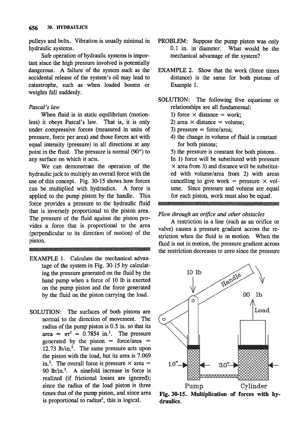
We can demonstrate the operation of the
hydraulic jack to multiply an overall force with the
use of this concept. Fig. 30-15 shows how forces
can be multiplied with hydraulics. A force is
applied to the pump piston by the handle. This
force provides a pressure to the hydraulic fluid
that is inversely proportional to the piston area.
The pressure of the fluid against the piston pro-
vides a force that is proportional to the area
(perpendicular to its direction of motion) of the
piston.
EXAMPLE 1. Calculate the mechanical advan-
tage of the system in Fig. 30-15 by calculat-
ing the pressure generated on the fluid by the
hand pump when a force of 10 lb is exerted
on the pump piston and the force generated
by the fluid on the piston carrying the load.
SOLUTION: The surfaces of both pistons are
normal to the direction of movement. The
radius of the pump piston is 0.5 in. so that its
area = Trr^ = 0.7854 in.^ The pressure
generated by the piston = force/area =
12.73 Ihl'm}. The same pressure acts upon
the piston with the load, but its area is 7.069
in.^. The overall force is pressure x area =
90 Ib/in.^. A ninefold increase in force is
realized (if frictional losses are ignored);
since the radius of the load piston is three
times that of the pump piston, and since area
is proportional to radius^, this is logical.
PROBLEM: Suppose the pump piston was only
0.1 in. in diameter. What would be the
mechanical advantage of the system?
EXAMPLE 2. Show that the work (force times
distance) is the same for both pistons of
Example 1.
SOLUTION: The following five equations or
relationships are all fundamental:
1) force X distance = work;
2) area x distance = volume;
3) pressure = force/area;
4) the change in volume of fluid is constant
for both pistons;
5) the pressure is constant for both pistons.
In 1) force will be substituted with pressure
X area from 3) and distance will be substitut-
ed with volume/area from 2) with areas
cancelling to give work = pressure x vol-
ume.
Since pressure and volume are equal
for each piston, work must also be equal.
Flow through an orifice and other obstacles
A restriction in a line (such as an orifice or
valve) causes a pressure gradient across the re-
striction when the fluid is in motion. When the
fluid is not in motion, the pressure gradient across
the restriction decreases to zero since the pressure
Pump Cylinder
Fig. 30-15. Multiplication of forces with hy-
draulics.
HYDRAULIC POWER SYSTEMS 657
through the fluid
is
constant according
to
Pascal's
law. When there
is a
flow across
a
restriction
useful mechanical energy
is
converted to (useless)
heat energy.
The
production
of
heat energy
is
proportional
to
both the pressure gradient and the
flow
rate.
Of
course, there
is no
flow through
a
valve that
is
completely closed.
In effect any line
is
really
an
orifice so there
is a pressure drop across it. Consequently there
is
always some energy loss through
a
line. Howev-
er,
the
energy losses
can
minimized
by
using
a
line
of
proper diameter
to
avoid high flow veloci-
ties,
avoiding sharp turns
in
flow patterns,
and
other proper design practices.
Hydraulic jack
The system in Fig. 30-15 is not very practical
since there
is a
very limited range
of
motion.
It
takes many operations of the hand pump to lift the
object
a
suitable distance.
A
check valve allows
flow in one direction only
so
that several opera-
tions
of the
handle
may be
combined
to
lift
the
load.
It
works
by
means
of a
ball that seats
against
a
seal.
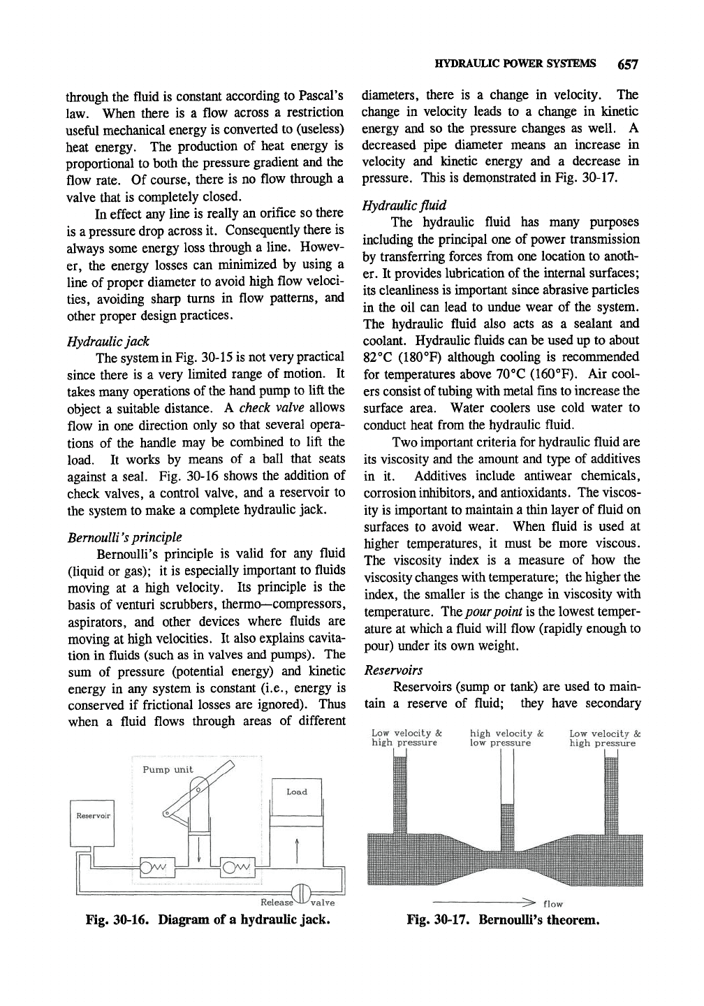
Fig.
30-16 shows
the
addition
of
check valves,
a
control valve,
and a
reservoir
to
the system to make
a
complete hydraulic jack.
Bernoulli's principle
Bernoulli's principle
is
valid
for any
fluid
(liquid
or
gas);
it is
especially important
to
fluids
moving
at a
high velocity.
Its
principle
is the
basis
of
venturi scrubbers, thermo—compressors,
aspirators,
and
other devices where fluids
are
moving
at
high velocities.
It
also explains cavita-
tion
in
fluids (such as
in
valves and pumps).
The
sum
of
pressure (potential energy)
and
kinetic
energy
in any
system
is
constant (i.e., energy
is
conserved
if
frictional losses
are
ignored). Thus
when
a
fluid flows through areas
of
different
Pump unit
Ow
iCy^'
Load
ift
diameters, there
is a
change
in
velocity.
The
change
in
velocity leads
to a
change
in
kinetic
energy
and so the
pressure changes
as
well.
A
decreased pipe diameter means
an
increase
in
velocity
and
kinetic energy
and a
decrease
in
pressure. This
is
demonstrated
in
Fig. 30-17.
Hydraulic fluid
The hydraulic fluid
has
many purposes
including the principal one
of
power transmission
by transferring forces from one location to anoth-
er.
It
provides lubrication of the internal surfaces;
its cleanliness is important since abrasive particles
in
the oil can
lead
to
undue wear
of
the system.
The hydraulic fluid also acts
as a
sealant
and
coolant. Hydraulic fluids can be used up
to
about
82°C (ISO'^F) although cooling
is
recommended
for temperatures above 70°C (160°F).
Air
cool-
ers consist of tubing with metal fins to increase the
surface area. Water coolers
use
cold water
to
conduct heat from the hydraulic fluid.
Two important criteria for hydraulic fluid
are
its viscosity and the amount and type
of
additives
in
it.
Additives include antiwear chemicals,
corrosion
inhibitors,
and antioxidants. The viscos-
ity is important to maintain
a
thin layer
of
fluid
on
surfaces
to
avoid wear. When fluid
is
used
at
higher temperatures,
it
must
be
more viscous.
The viscosity index
is a
measure
of how the
viscosity changes with temperature; the higher the
index,
the
smaller
is the
change
in
viscosity with
temperature. The pour point is the lowest temper-
ature
at
which
a
fluid will flow (rapidly enough to
pour) under
its
own weight.
Reservoirs
Reservoirs (sump
or
tank)
are
used
to
main-
tain
a
reserve
of
fluid; they have secondary
Low velocity
&:
high pressure
high velocity
&:
low pressure
Low velocity 8c
high pressure
Release^-i^ valve
Fig. 30-16. Diagram
of a
hydraulic jack.
-> flow
Fig. 30-17. Bernoulli's theorem.
658 30. HYDRAULICS
purposes of oil cooling and separation of air and
contaminants from the oil. Small amounts of fluid
may leak from systems, and cylinders cause
system volume changes according to their posi-
tions.
Reservoirs may be pressurized (an air
pressure supply maintains the pressure) or vented
to the atmosphere. Obviously, pressurized sys-
tems must be sealed; therefore, they are more
resistant to contamination and condensation forma-
tion. A relatively large reservoir can also help
keep the hydraulic fluid cool. Components of
reservoirs include filler cap, fluid level gauge,
outlet (to pump), inlet with filter to remove parti-
cles that would otherwise damage the pump, drain
plug (which may be magnetic to trap metal parti-
cles),
inspection plate, and pressure regulator. A
baffle may be used to separate inlet and outlet
flows for cooling and contaminant separation.
Reservoirs should be relatively high and
narrow to give a column of fluid above the pump
inlet. This decreases the chance of air entering
the system by formation of a vortex. Any air will
greatly reduce the efficiency of the system since
the fluid then becomes compressible.
Filters and strainers
Strainers are coarse filters used to remove
relatively large pieces of debris. Filters have a
porous medium that is used to remove insoluble
solids from hydraulic fluid. Cotton, cloth, and
resin—reinforced paper are often the porous
media. A good filter will remove solids of
10
fim
diameter and larger. The pressure drop across a
filter with fine pores may be as much as 25 psi, so
they should not be used at pump inlets since
cavitation may result. Strainers may be used with
caution at pump inlets if the pressure drop is small
enough to avoid problems. Filters are sometimes
used with automatic bypass valves that open as the
filter becomes plugged so that flow in the system
can continue. A color indicator may be used to
indicate the flow bypass condition.
Transfer of hydraulic fluid
Hydraulic fluid travels through tubes that are
depicted as single lines in schematic diagrams. A
solid line designates a working line that carries the
bulk of the fluid. Pilot lines are used to control
components and are represented by lines with long
dashes. A drain line is represented by short
dashes and is used to carry leakage oil back to the
reservoir.
Hydraulic fluid may be transferred with
pipes,
tubing, or hose. Pipes are often of
(nonstainless) steel (do not use galvanized steel
since zinc is fairly reactive with some fluid addi-
tives).
They are rigid and not meant to be bent.
The schedule number refers to the wall thickness;
the actual thickness and pressure rating depend on
the overall nominal pipe diameter. Schedules are
10,
20, 30, 40, 60, 80, 100, 120, 140, and 160
with 40, 80, and 160 as common designations.
Schedule 40 is used for low—pressure lines,
schedule 80 is used for high—pressure lines, and
schedule 160 is used for very high pressure lines.
Pipes of larger inside diameter generally operate at
lower pressures. For example, a nominal pipe
diameter of Vi in. for steel pipe has an outside
diameter of 0.84 in. The inside diameters are
0.622, 0.564, and 0.466 in. for schedules 40, 80,
and 160, respectively. The operating pressure
limits are 2300, 4100, and 7300 psi and the burst
pressures are 15,500 psi, 21,000 psi, and 26,700
psi,
respectively. (Notice the safety factors of
6.74, 5.12, and 3.66; minimum safety factors are
8 below 1000 psi, 6 in the pressure range of
1000—2500 psi, and 4 above 2500 psi.) For steel
pipe of 2 in. nominal diameter, the outside diame-
ter is 2.375 in., and the inside diameters are
2.067,
1.939,
and 1.689 in., for schedule 40, 80,
and 160, respectively. The working pressures are
1500,
2500, and 4600 psi, respectively.
Tubes are often of stainless or nonstainless
steel (do not use galvanized steel) that is seamless
or welded. They are usually of relatively small
diameter and relatively thin—walled. Tubes may
be bent into shape, but generally should not bend
during routine operation of a hydraulic system.
Tubes are used with a variety of fittings. Flare
fittings are usually 37°, although 45° may be used
in certain applications. Swage fittings work by
compressing the tubing so that its outside diameter
increases to seal around a retaining ring. Bite
fittings use a retaining ring which is compressed
into (bites) the tube. Some fittings may be brazed
on to form a seal with the tubing. Avoid the use
of straight—line connections that do not allow for
expansion and contraction.
HYDRAULIC POWER SYSTEMS 659
Hydraulic hoses have an inner tube, rein-
forcement layer(s), and a cover. The inner tube is
often of synthetic rubber. The reinforcement
layers are constructed of steel or fabric braided
mesh, although several of spiral plies wrapped in
opposite directions are also used. Skive is the
process of removing the outer cover of a hydraulic
hose.
Avoid loops, twists, rubbing, heat, kinks,
and strained connections with hydraulic hoses.
Hydraulic pumps and motors
The energy required to drive components of
a hydraulic system is derived by the pump, which
has been discussed in detail. Usually, hydraulic
pumps are positive displacement.
The theoretical flow rate (0 is equal to the
displacement (d) per revolution times the number
of revolutions per minute
{ri).
If Q is reported in
gallons per hour and d is in in.^ then Q =
dxn/(231 in.Vgal). The power generated (in
horsepower) is equal to the outlet pressure in psi
times the flow rate in gallons per minute divided
by 1714 (gal-lb/in.^-min-hp).
Hydraulic motors operate very similarly to
hydraulic pumps (positive displacement pumps),
except that the forced flow is converted to rotary
motion. In fact, most hydraulic pumps can be
used as hydraulic motors with little or no modifi-
cation. A hydrostatic transmission
uses
a pump at
the input and a motor at the output.
Accumulators
In systems where the hydraulic power is used
intermittently, accumulators can be used to store
hydraulic fluid under pressure so that when it is
required a fluid delivery rate higher than that of
the pump may be achieved. Accumulators are
pressurized chambers that hold the fluid. Pressure
is maintained with a gas (contained in a bladder),
a weight, or a spring. A weight does provide a
constant pressure, although this system cannot be
used practically on mobile hydraulic systems.
Valves
The path of the fluid in motion is directed by
valves. Valves also control the pressure or flow
rate of the fluid. Relief valves limit the maximum
pressure in the system. The poppet prevents flow
when it closes against the seat. An envelope is the
valve symbol and as many envelopes are used as
there are distinct valve positions.
Pressure control valves operate in a balanced
condition; that is, a force is used to counteract the
pressure of the hydraulic fluid. The opposing
force may be generated by a spring with a valve
that moves into a balanced position for easy
operation. The detailed presentation of valves and
groups of
valves
is beyond the scope of this work.
Cylinders
Cylinders are linear actuators and may be
single or double acting. They consist of the
barrel, the piston, the piston rod, and suitable end
caps and seals. Cylinder cushions may be used at
one or both ends to prevent hammering. Fig. 30-
15 depicts a single—acting ram; it requires the
load to return it to the unextended position.
Double—acting cylinders have two hydraulic lines,
one on each side of the piston, so that the cylinder
can be made to operate with power in either
direction without depending on an external force.
Telescoping cylinders have four or five concentric
cylinders (sleeves) when collapsed that can each
extend separately so that the extended length can
be much more than the collapsed length.
Motors
Hydraulic motors are analogous to hydraulic
pumps but operate in "reverse" with a high-
energy fluid being converted into rotary motion
with a certain angular velocity and torque. Gear,
vane,
and piston motors are common.
30.7 TROUBLESHOOTING HYDRAULIC
POWER SYSTEMS
Safety during repair of hydraulic systems
Normal safety rules should be observed;
notify all people involved of the who, what,
where, when, and whys of the repair and how it
will affect them. When working with hydraulic
systems it is preferable to shut the system down
completely. Electrical switches must be tagged
and locked out. The fluid pressure must be
relieved, and all gauges should indicate no pres-
sure in the system. Accumulators must be bled.
Heavy weights supported by the hydraulics must
be locked into position. When working on these
systems always assume there is pressure in the
system and allow fluid to drain before completely
breaking a connection. Fluid should be collected
in suitable vessels to prevent floors from becoming
660
30.
HYDRAULICS
slick with
it.
Always read
the
safety instructions
for
a
given system.
Troubleshooting hydraulic
systems
When troubleshooting hydraulic systems
it is
important
to
have
the
drawings available. Keep
in
mind that modifications
to the
system
may not be
transcribed
to the
original drawings.
The
operator
should always
be
consulted
to
determine
how the
system
is
operating differently from normal.
If
the system
is
safe
to
operate,
one may
wish
to
operate
it to
determine
the
extent
of
the problem.
Contaminated hydraulic fluid
is the
most
common cause
of
failure
in
hydraulic systems.
The fluid should
be
kept clean
to
avoid problems.
Pump
cavitation
Pump cavitation occurs when voids
(gas
bubbles) form
in the
fluid within the pump, usual-
ly near
the
inlet.
As the
voids collapse, noise
(like thunder)
is
emitted. (Cavitation
is
really
boiling
of the
liquid
at
reduced pressure.) Pump
cavitation often occurs because fluid
is not
enter-
ing
the
pump fast enough
at the
pump intake.
Many causes
can
contribute
to
this.
If the
fluid
viscosity
is too low
(such
as in a
cold system) then
it flows slowly.
If
the fluid reservoir
is far
below
the intake, then
a
partial vacuum
is
already
formed. Dirty intake filters, intake lines with
small internal diameters,
and air in the
system
all
decrease
the
rate
of
fluid entering
the
pump.
Problems with
the
pump itself
may
also cause
pump cavitation.
Low
or
no
system
pressure
Low system pressure
can be
caused
by a
variety
of
conditions. Dirty fluid will quickly
make check valves plug into their open positions.
Relief valves
may
stick
in an
open position
or,
worse
yet, in a
closed position where fluid pres-
sure builds
up
until some component
of
the system
fails catastrophically. Faulty
or
improperly
set
relief valves
can
lead
to low
system pressure.
Reservoirs must have adequate fluid.
The
reservoirs should
be
large enough
to
allow
air
bubbles
to
escape before
the
fluid reenters
the
system. Unexpected contributions include improp-
erly installed shaft seals.
If there
is a
complete lack
of
system pres-
sure,
make sure
the
pump
is
rotating
and
rotating
in
the
correct direction.
The energy
of a
hydraulic system
is:
h.p.
=
[gal/min
x
pressure (psig)]/
1714
Hydraulic
symbols
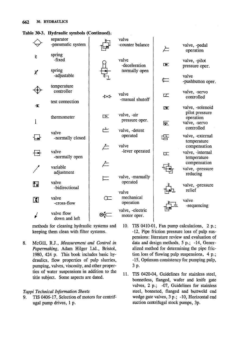
Table
30-3
lists many hydraulic symbols.
The energy triangle
of a
pump points outward
showing
it is a
source
of
hydraulic energy;
the
energy triangle
of a
motor points inward showing
it uses hydraulic energy.
Two
energy triangles
indicate
the
pump
or
motor
is
reversible.
30.8 ANNOTATED BIBLIOGRAPHY
Pumps
1.
The
Hydraulic Institute (Parsippany,
New
Jersey,
USA) is a
nonprofit industry associa-
tion working
in the
engineering, manufac-
turing,
and
application of pumping equipment
since
1917.
They publish Pump Standards.
2.
Buchanan,
E.R.,
High velocity spray coat-
ings.
Pumps
and
Systems
Mag.
1(3):
57-59
(1993).
This
is a
good summary
of
hard
coatings
use.
3.
Karassik,
I.J.,
Centrifugal Pump
Clinic,
2nd
ed.. Marcel Dekker,
Inc., New
York,
1989.
Valves
4.
Anonymous, Valves, Pulp
&
Paper Buyers
Guide .-25-29(1992).
5.
Dresch,
C, The
selection
and
maintenance
of valves
for the
control
of
fugitive emis-
sions,
Tappi
J.
77(8):46-50(1994);
ibid..
Valve
Mag.
Spring,
1994,
from Valve Manu-
facturing Association
of
America,
1050 17th
St.
NW,
Washington,
D.C.
20036.
Miscellaneous
6. Brink, K.L. and R.F. Van Lieshout, Applica-
tion
and
selection guidelines
for ac
system
drives: part
1,
Tappi
J.
76(4):
143-155(1993)
and part
2, ibid\
76(5):
173-180(1993).
7. Anders,
J.E., Sr.,
Industrial Hydraulics
Troubleshooting,
McGrsLVz-mW,
1982,
176 p.
This
is a
practical,
but not
comprehensive,
overview
of
troubleshooting already installed
systems
and
starting
up new
systems.
A
number
of
pages (with photographs) describe
catastrophic failures caused
by
dirt
and
con-
taminants
in
systems. Other sections describe
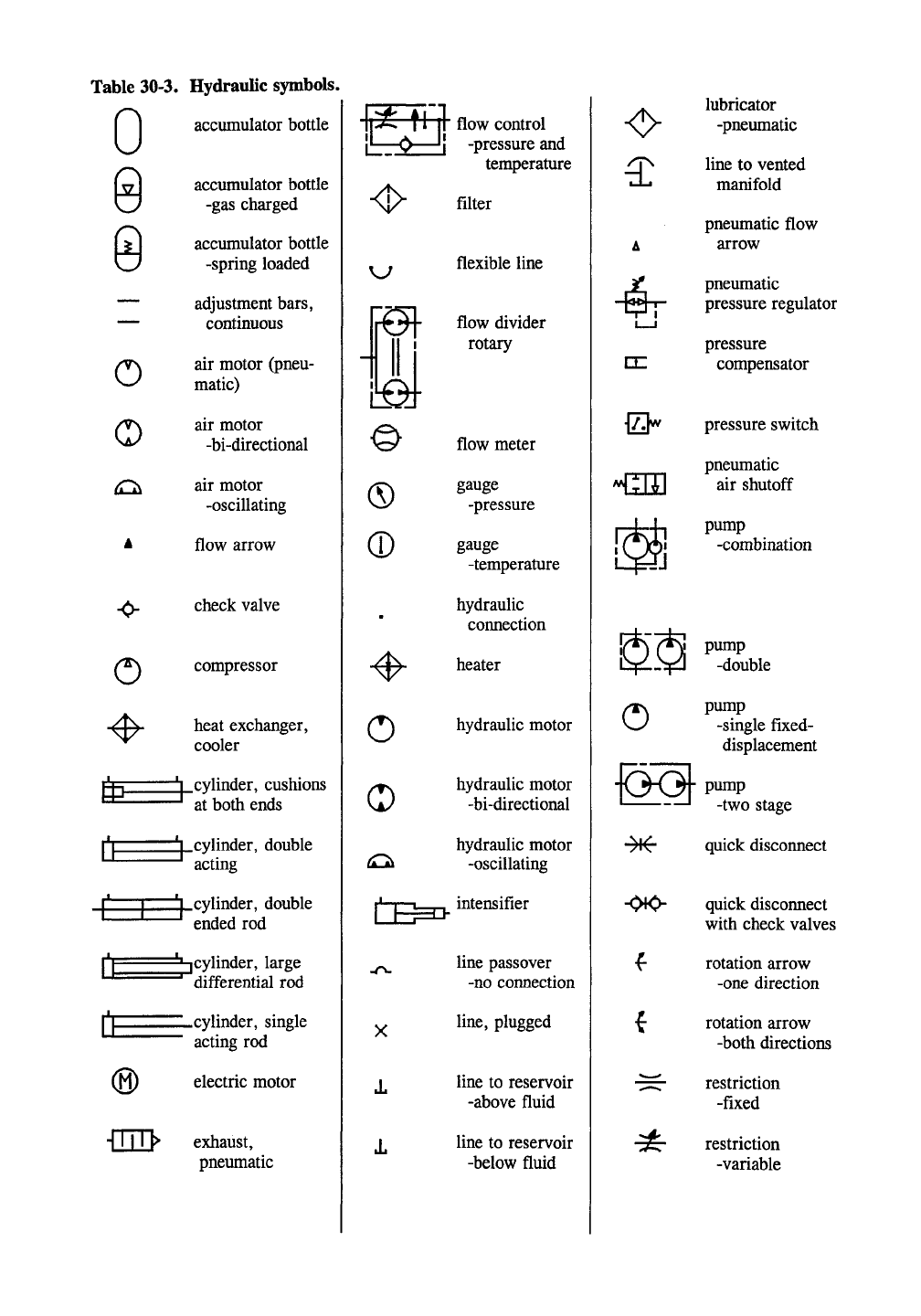
Table 30-3. Hydraulic symbols.
accumulator bottle
0
o
o
•0-
CE
accumulator bottle
-gas charged
accimiulator bottle
-spring loaded
adjustment bars,
continuous
air motor (pneu-
matic)
air motor
-bi-directional
air motor
-oscillating
flow arrow
check valve
(^ compressor
heat exchanger,
cooler
!h cylinder, cushions
at both ends
i.cylinder,
double
acting
.cylinder, double
ended rod
^cylinder, large
differential rod
®
-cylinder, single
acting rod
electric motor
exhaust,
pneimiatic
flow control
!•—<>•—'I -pressure and
®
®
o
o
temperature
filter
flexible line
flow divider
rotary
flow meter
gauge
-pressure
gauge
-temperature
hydraulic
connection
heater
hydraulic motor
hydraulic motor
-bi-directional
hydraulic motor
t^ -oscillating
:^
intensifier
1
line passover
-no connection
line,
plugged
line to reservoir
-above fluid
line to reservoir
-below fluid
A
I I
&
431]
m
lubricator
-pneumatic
line to vented
manifold
pneumatic flow
arrow
pneumatic
pressure regulator
pressure
compensator
pressure switch
pneumatic
air shutoff
pump
-combination
o
pump
-double
pump
-single fixed-
displacement
•0K>-
quick disconnect
quick disconnect
with check valves
rotation arrow
-one direction
rotation arrow
-both directions
restriction
-fixed
restriction
-variable
662
30.
HYDRAULICS
Table 30-3. Hydraulic symbols (Continued).
•
1
-Q-
separator
-pneumatic system
spring
-fixed
spring
-adjustable
temperature
controller
test connection
thermometer
valve
-normally closed
valve
-normally open
variable
adjustment
valve
-bidirectional
valve
-cross-flow
valve flow
down and left
I—I
^1
ULJ
-lx^
HE
rw4v-
valve
-counter balance
valve
-deceleration
normally open
valve
-manual shutoff
valve, -air
pressure oper.
valve, -detent
operated
valve
-lever operated
valve, -manually
operated
valve
mechanical
operation
valve, -electric
motor oper.
valve, -pedal
operation
valve, -pilot
pressure oper.
valve
-pushbutton oper.
valve, -servo
controlled
valve, -solenoid
pilot pressure
operation
valve, -servo
controlled
valve, -external
temperature
compensation
valve, -internal
temperature
compensation
valve, -pressure
reducing
^ valve, -pressure
Tt^hL relief
h
XEL
(t=
m
EE
E
ci:
valve
-sequencing
methods for cleaning hydraulic systems and
keeping them clean with filter systems.
8. McGill, R.J., Measurement and Control in
PapermaUng, Adam Hilger Ltd., Bristol,
1980,
424 p. This book includes basic hy-
draulics, flow properties of pulp slurries,
pumping, valves, viscosity, and other proper-
ties of water suspensions in addition to the
title subject. Some aspects are dated.
Tappi Technical Information Sheets
9. TIS 0406-17, Selection of motors for
centrif-
ugal pump drives, 1 p.
10.
TIS
0410-01,
Fan pump calculations, 2 p.;
-12,
Pipe friction pressure loss of pulp sus-
pensions: literature review and evaluation of
data and design methods, 5 p.; -14, Gener-
alized method for determining the pipe fric-
tion loss of flowing pulp suspensions, 4 p.;
-15,
Optimum consistency for pumping pulp,
3 p.
11.
TIS 0420-04, Guidelines for stainless steel,
bonnetless, flanged, wafer and knife gate
valves, 2 p.; -07, Guidelines for stainless
steel, bonneted, flanged and buttweld end
wedge gate valves, 3 p.; -10, Horizontal end
suction centrifugal stock pumps, 3p.
31
PROCESS CONTROL
31.1 INTRODUCTION
Introduction
The objective of process control is to keep
key process operating parameters within narrow
bounds of the reference value or setpoint. The
importance of this and some aspects of this have
been discussed in Chapter 20. This section will
describe the theory behind control circuits to
maintain automatic control over a process.
Automatic control
The basis of automatic control (where a
machine or electronic circuit is the control as
opposed to a human being) is the control loop. A
control loop for a given process must have at least
one sensor, the controller (that decides what to do
with the information that is collected), and a
control element to which the results are applied.
A good example of automatic control is
electric heating of a house in a cold environment,
a process where a single variable is controlled. A
thermostat (sensor) monitors the temperature.
When the temperature drops below the setpoint a
switch (controller) is closed and the heater (control
element) comes on. When the temperature rises
above the setpoint, the switch opens and the heater
is turned off.
The difference between the actual value and
the setpoint is called the error. The controller
reads the error and makes a decision. The action
taken can be very simple to very complicated,
depending on the system and the size of the
acceptable error. When heating a house the
actuator turns the furnace on or off if the error is
below or above the setpoint, respectively. It is a
very simple control, but the error ranges to 2°C,
not very precise by many standards.
This system is called
2i
process control loop.
This is 2i feedback loop because the desired result
is determined and the information (the error) is fed
back to the controller for appropriate action.
In a feedforward loop it is generally not
convenient to use the desired result to control the
process so another variable must be substituted.
For example, we refine pulp to influence the
properties of the final sheet; however, it is not
convenient to use any paper properties to control
refining level because the dead time is too high.
The dead time is a measure of the length of time
before a change in the actuator (refining level)
causes a change at the sensor (paper properties).
Changes in refining level may not be seen in the
paper for several minutes to several days if stock
storage is used. In this case the refining level is
controlled by monitoring the energy input to the
refiners for a given amount of
pulp.
Two sensors
(stock flow rate and energy consumption) are
combined into one variable (refining intensity).
One must know the relationship between refining
intensity and paper properties.
31.2 SENSORS
Definition
The sensor is a device which converts a
change in a parameter (such as temperature,
position, or pressure) to a change in a electric or
pneumatic signal (information). (A sensor is one
type of
transducer,
a device that changes a signal
from one form to another form, such as a change
in voltage to a change in current or a change in
light to a change in voltage.)
Transfer function
A transfer function relates the value of the
parameter to be measured with the output of the
sensor. For example, with a reference point of
0°C,
type J thermocouples (iron—constatan) give
a signal of 0.0515 mV per degree Celsius (the
sensitivity) over a narrow range. The relationship
is not linear over a wide range of temperatures, so
one might want to use a more sophisticated trans-
fer function; in fact, the National Bureau of Stan-
dards specifies a 5th—order polynomial equation
for the temperature range of 0° to 760°C with a
accuracy of
0.1
°C
for the type J thermocouple.
This signal undergoes some processing in
most (except the most basic) systems. For exam-
ple,
electrical information
is
reliably transmitted in
663