Biermann Ch. Handbook of Pulping and Papermaking
Подождите немного. Документ загружается.

644 30. HYDRAULICS
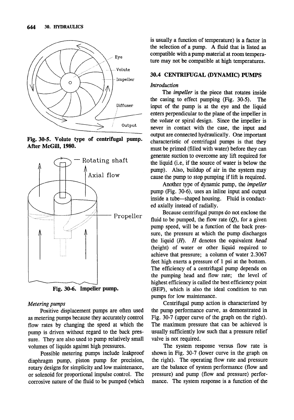
Fig. 30-5. Volute type of centrifugal pump.
After McGiU, 1980.
/-"•^^r^ — Rotating shaft
Axial flow
Propeller
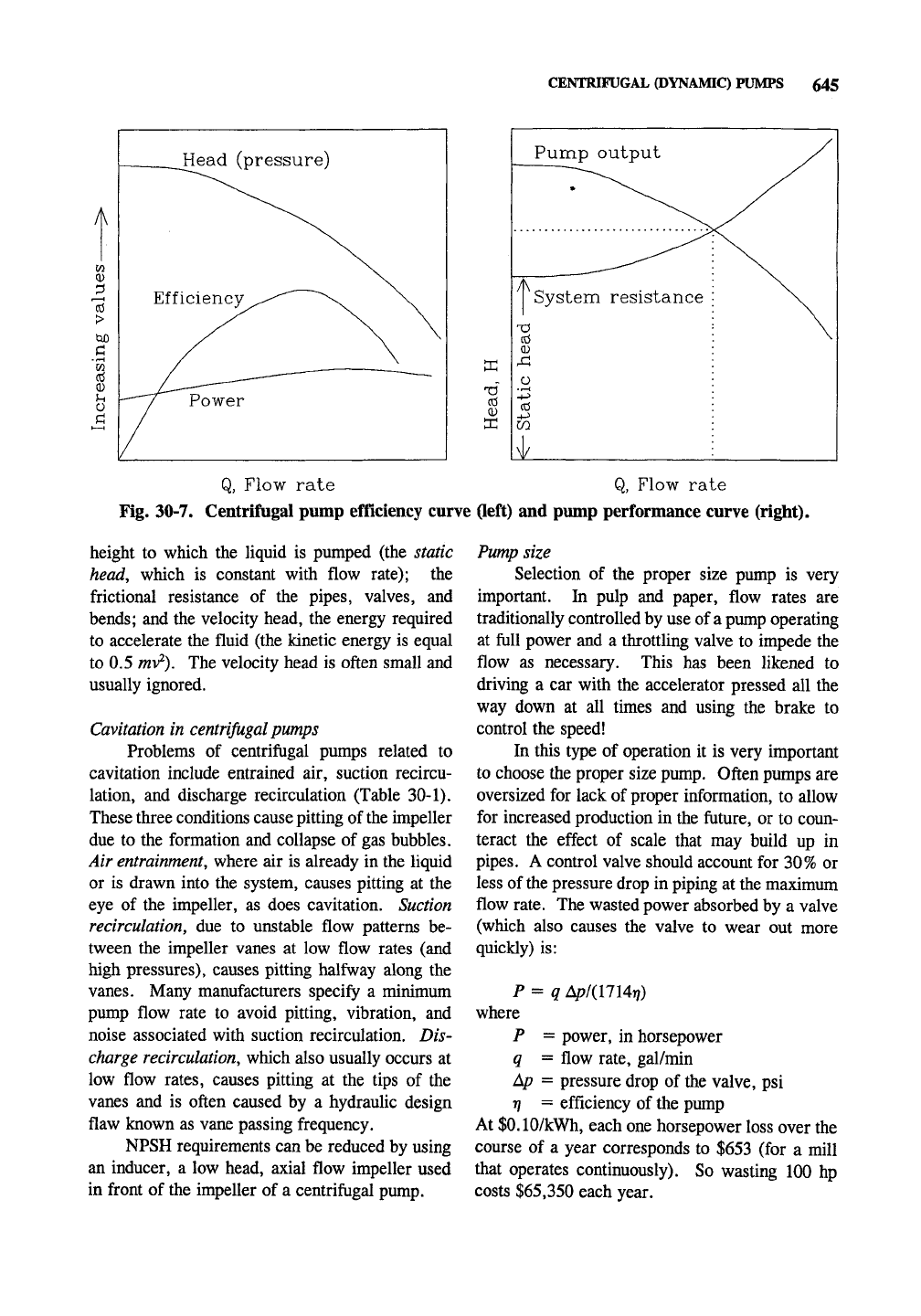
Fig. 30-6. Impeller pump.
Metering pumps
Positive displacement pumps are often used
as metering pumps because they accurately control
flow rates by changing the speed at which the
pump is driven without regard to the back pres-
sure.
They are also used to pump relatively small
volumes of liquids against high pressures.
Possible metering pumps include lealq)roof
diaphragm pump, piston pump for precision,
rotary designs for simplicity and low maintenance,
or solenoid for proportional impulse control. The
corrosive nature of the fluid to be pumped (which
is usually a function of temperature) is a factor in
the selection of a pump. A fluid that is listed as
compatible with a pump material at room tempera-
ture may not be compatible at high temperatures.
30.4 CENTRIFUGAL (DYNAMIC) PUMPS
Introduction
The impeller is the piece that rotates inside
the casing to effect pumping (Fig. 30-5). The
input of the pump is at the eye and the liquid
enters perpendicular to the plane of
the
hnpeller in
the volute or spiral design. Since the impeller is
never in contact with the case, the input and
output are connected hydraulically. One important
characteristic of centrifugal pumps is that they
must be primed (filled with water) before they can
generate suction to overcome any lift required for
the liquid (i.e, if the source of water is below the
pump).
Also, buildup of air in the system may
cause the pump to stop pumping if lift is required.
Another type of dynamic pump, the impeller
pump (Fig. 30-6), uses an inline input and output
inside a tube—shaped housing. Fluid is conduct-
ed axially instead of radially.
Because centriftigal pumps do not enclose the
fluid to be pumped, the flow rate (Q), for a given
pump speed, will be a ftinction of the back pres-
sure,
the pressure at which the pump discharges
the liquid {H). H denotes the equivalent head
(height) of water or other liquid required to
achieve that pressure; a column of water 2.3067
feet high exerts a pressure of
1
psi at the bottom.
The efficiency of a centrifugal pump depends on
the pumping head and flow rate; the level of
highest efficiency is called the best efficiency point
(BEP),
which is also the ideal condition to run
pumps for low maintenance.
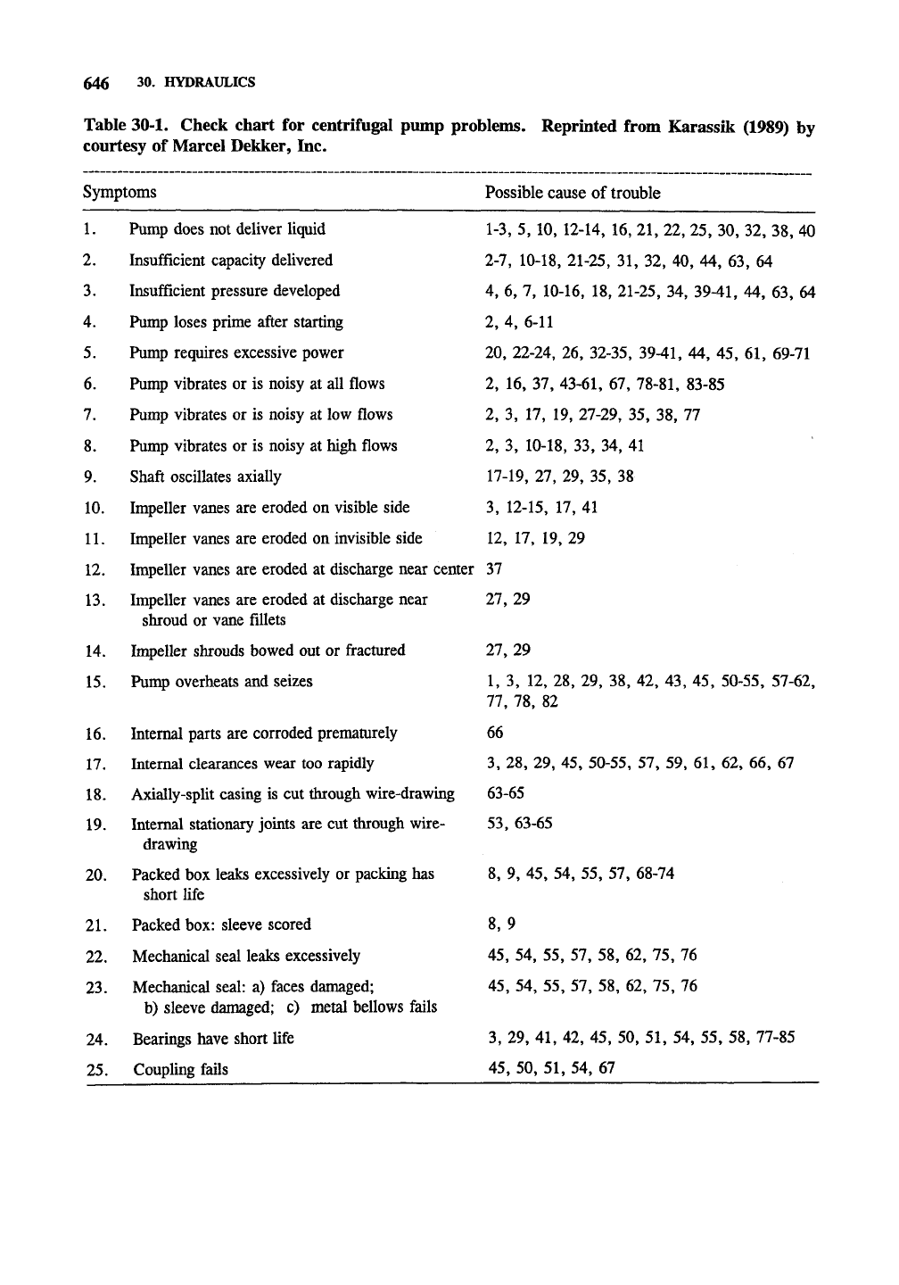
Centrifugal pump action is characterized by
the pump performance curve, as demonstrated in
Fig. 30-7 (upper curve of the graph on the right).
The maximum pressure that can be achieved is
usually sufficiently low such that a pressure relief
valve is not required.
The system response versus flow rate is
shown in Fig. 30-7 (lower curve in the graph on
the right). The operating flow rate and pressure
are the balance of system performance (flow and
pressure) and pump (flow and pressure) perfor-
mance. The system response is a ftinction of the
CENTRIFUGAL (DYNAMIC) PUMPS 645
Head (pressure)
XI
cd
0)
Q, Flow rate Q, Flow rate
Fig. 30-7. Centrifugal pump efficiency curve (left) and pump performance curve (right).
height to which the liquid is pumped (the static
head,
which is constant with flow rate); the
frictional resistance of the pipes, valves, and
bends;
and the velocity head, the energy required
to accelerate the fluid (the kinetic energy is equal
to 0.5
mv^).
The velocity head is often small and
usually ignored.
Cavitation in
centrifugal
pumps
Problems of centrifugal pumps related to
cavitation include entrained air, suction recircu-
lation, and discharge recirculation (Table 30-1).
These three conditions cause pitting of
the
impeller
due to the formation and collapse of gas bubbles.
Air
entrainment,
where air is already in the liquid
or is drawn into the system, causes pitting at the
eye of the impeller, as does cavitation. Suction
recirculation, due to unstable flow patterns be-
tween the impeller vanes at low flow rates (and
high pressures), causes pitting halfway along the
vanes.
Many manufacturers specify a minimum
pump flow rate to avoid pitting, vibration, and
noise associated with suction recirculation. Dis-
charge recirculation, which also usually occurs at
low flow rates, causes pitting at the tips of the
vanes and is often caused by a hydraulic design
flaw known as vane passing frequency.
NPSH requirements can be reduced by using
an inducer, a low head, axial flow impeller used
in front of the impeller of a centrifugal pump.
Pump size
Selection of the proper size pump is very
important. In pulp and paper, flow rates are
traditionally controlled by use of
a
pump operating
at ftiU power and a throttling valve to impede the
flow as necessary. This has been likened to
driving a car with the accelerator pressed all the
way down at all times and using the brake to
control the speed!
In this type of operation it is very important
to choose the proper size pump. Often pumps are
oversized for lack of proper information, to allow
for increased production in the future, or to coun-
teract the effect of scale that may build up in
pipes.
A control valve should account for 30% or
less of the pressure drop in piping at the maximum
flow
rate.
The wasted power absorbed by a valve
(which also causes the valve to wear out more
quickly) is:
P = q /Sp/iUUrj)
where
P = power, in horsepower
q = flow rate, gal/min
Ap = pressure drop of the valve, psi
rj = efficiency of the pump
At $0.10/kWh, each one horsepower loss over the
course of a year corresponds to $653 (for a mill
that operates continuously). So wasting 100 hp
costs $65,350 each year.
646 30. HYDRAULICS
Table 30-1. Check chart for centrifugal pump problems. Reprinted from Karassik (1989) by
courtesy of Marcel Dekker, Inc.
Symptoms Possible cause of trouble
1.
Pump does not deliver liquid 1-3, 5, 10, 12-14, 16, 21, 22, 25, 30, 32, 38, 40
2.
Insufficient capacity delivered 2-7, 10-18, 21-25, 31, 32, 40, 44, 63, 64
3.
Insufficient pressure developed 4, 6, 7, 10-16, 18, 21-25, 34,
39-41,
44, 63, 64
4.
Pump loses prime after starting 2, 4, 6-11
5.
Pump requires excessive power 20, 22-24, 26, 32-35,
39-41,
44, 45, 61, 69-71
6. Pump vibrates or is noisy at all flows 2, 16, 37,
43-61,
67,
78-81,
83-85
7.
Pump vibrates or is noisy at low flows 2, 3, 17, 19, 27-29, 35, 38, 77
8. Pump vibrates or is noisy at high flows 2, 3, 10-18, 33, 34, 41
9. Shaft oscillates axially 17-19, 27, 29, 35, 38
10.
Impeller vanes are eroded on visible side 3, 12-15, 17, 41
11.
Impeller vanes are eroded on invisible side 12, 17, 19, 29
12.
Impeller vanes are eroded at discharge near center 37
13.
Impeller vanes are eroded at discharge near 27, 29
shroud or vane fillets
14.
Impeller shrouds bowed out or fractured 27, 29
15.
Pump overheats and seizes 1, 3, 12, 28, 29, 38, 42, 43, 45, 50-55, 57-62,
77,
78, 82
16.
Internal parts are corroded prematurely 66
17.
Internal clearances wear too rapidly 3, 28, 29, 45, 50-55, 57, 59, 61, 62, 66, 67
18.
Axially-split casing is cut through wire-drawing 63-65
19.
Internal stationary joints are cut through wire- 53, 63-65
drawing
20.
Packed box leaks excessively or packing has 8, 9, 45, 54, 55, 57, 68-74
short Hfe
21.
Packed box: sleeve scored 8, 9
22.
Mechanical seal leaks excessively 45, 54, 55, 57, 58, 62, 75, 76
23.
Mechanical seal: a) faces damaged; 45, 54, 55, 57, 58, 62, 75, 76
b) sleeve damaged; c) metal bellows fails
24.
Bearings have short life 3, 29, 41, 42, 45, 50, 51, 54, 55, 58, 77-85
25.
Coupling fails 45, 50, 51, 54, 67
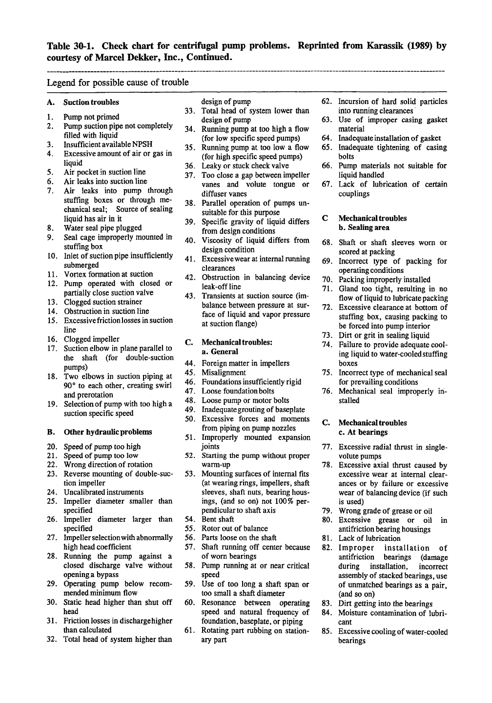
Table 30-1. Check chart for centrifugal pump problems,
courtesy of Marcel Dekker, Inc., Contmued.
Reprinted from Karassik (1989) by
Legend for possible cause of trouble
A.
Suction
troubles
1.
2.
3.
4.
5.
6.
7.
8.
9.
10.
11.
12.
13.
14.
15.
16.
17.
18.
19.
Pump not primed
Pump suction
pipe
not completely
filled with liquid
Insufficient available
NPSH
Excessive amount of air or gas in
liquid
Air pocket
in
suction line
Air leaks into suction line
Air leaks into pump through
stuffing boxes or through me-
chanical seal; Source of sealing
liquid has air in it
Water seal pipe plugged
Seal cage improperly mounted in
stuffing box
Inlet of suction
pipe
insufficiently
submerged
Vortex formation at suction
Pump operated with closed or
partially close suction valve
Clogged suction strainer
Obstruction in suction line
Excessive friction losses
in
suction
line
Clogged impeller
Suction elbow in plane parallel to
the shaft (for double-suction
pumps)
Two elbows in suction piping at
90° to each other, creating swirl
and prerotation
Selection of
pump
with too high a
suction specific speed
B.
Other hydraulic problems
20.
Speed of
pump
too high
21.
Speed of
pump
too low
22.
Wrong direction of rotation
23.
Reverse mounting of double-suc-
tion impeller
24.
Uncalibrated instruments
25.
Impeller diameter smaller than
specified
26.
Impeller diameter larger than
specified
27.
Impeller selection
with
abnormally
high head coefficient
28.
Running the pump against a
closed discharge valve without
opening a
bypass
29.
Operating pump below recom-
mended minimum flow
30.
Static head higher than shut off
head
31.
Friction
losses
in discharge higher
than calculated
32.
Total head of system higher than
design of pump
33.
Total head of system lower than
design of pump
34.
Running
pump
at too high a flow
(for low specific speed pumps)
35.
Running pump at too low a flow
(for high specific speed pumps)
36.
Leaky or stuck check valve
37.
Too close a gap between impeller
vanes and volute tongue or
difftiser vanes
38.
Parallel operation of pumps un-
suitable for this purpose
39.
Specific gravity of liquid differs
from design conditions
40.
Viscosity of liquid differs from
design condition
41.
Excessive wear at internal running
clearances
42.
Obstruction in balancing device
leak-offline
43.
Transients at suction source (im-
balance between pressure at sur-
face of liquid and vapor pressure
at suction flange)
C.
Mechanical troubles:
a. General
44.
Foreign matter in impellers
45.
Misalignment
46.
Foundations insufficiently rigid
47.
Loose foundation bolts
48.
Loose pump or motor bolts
49.
Inadequate grouting of baseplate
50.
Excessive forces and moments
from piping on pump nozzles
51.
Improperly mounted expansion
joints
52.
Starting the pump without proper
warm-up
53.
Mounting surfaces of internal fits
(at wearing
rings,
impellers, shaft
sleeves, shaft nuts, bearing hous-
ings,
(and so on) not 100% per-
pendicular to shaft axis
54.
Bent shaft
55.
Rotor out of balance
56.
Parts loose on the shaft
57.
Shaft running off center because
of worn bearings
58.
Pump running at or near critical
speed
59.
Use of too long a shaft span or
too small a shaft diameter
60.
Resonance between operating
speed and natural frequency of
foundation,
baseplate,
or piping
61.
Rotating part rubbing on station-
ary part
62.
Incursion of hard solid particles
into running clearances
63.
Use of improper casing gasket
material
64.
Inadequate installation of gasket
65.
Inadequate tightening of casing
bolts
66.
Pump materials not suitable for
liquid handled
67.
Lack of lubrication of certain
couplings
C Mechanical troubles
b.
Sealing area
68.
Shaft or shaft sleeves worn or
scored at packing
69.
Incorrect type of packing for
operating conditions
70.
Packing improperly installed
71.
Gland too tight, resulting in no
flow of liquid to lubricate packing
72.
Excessive clearance at bottom of
stuffing box, causing packing to
be forced into pump interior
73.
Dirt or grit in sealing liquid
74.
Failure to provide adequate cool-
ing liquid to water-cooled stuffing
boxes
75.
Incorrect type of mechanical seal
for prevailing conditions
76.
Mechanical seal improperly in-
stalled
C.
Mechanical troubles
c. At bearings
77.
Excessive radial thrust in single-
volute pumps
78.
Excessive axial thrust caused by
excessive wear at internal clear-
ances or by failure or excessive
wear of balancing
device
(if such
is used)
79.
Wrong grade of grease or oil
80.
Excessive grease or oil in
antifriction bearing housings
81.
Lack of lubrication
82.
Improper installation of
antifriction bearings (damage
during installation, incorrect
assembly of stacked
bearings,
use
of unmatched bearings as a pair,
(and so on)
83.
Dirt getting into the bearings
84.
Moisture contamination of lubri-
cant
85.
Excessive cooling
of water-cooled
bearings
648 30. HYDRAULICS
Controlling
the process flow
The process flow can be controlled by three
methods. 1) With flow splitting a portion of the
flow can be recirculated to the supply vessel or
suction side of the pump, as in the stuff box of a
paper machine. 2) The pump head may be
changed by varying the speed of the pump (either
by using a variable speed motor or some type of
transmission). This method offers the potential to
be energy efficient where flow rate differences are
high. 3) The system curve can be altered, for
example, by using a throttling valve to increase
the system flow losses.
Variable
speed motors
Variable speed motors (especially NEMA B
squirrel cage AC induction motors) may be operat-
ed by alternating current (AC) variable frequency
drive (VFD) or by varying the voltage and current
to DC motors (Brink and Van Lieshout, 1993).
With VFD normal alternating current is converted
to direct current (DC) and from DC, using elec-
tronic circuits, to variable frequency and voltage
AC.
The speed of AC motors is dependent upon
the frequency of the power source, if an adequate
voltage is supplied. Variable torque motors are
often used with centrifugal pumps. While the
initial cost of these systems is higher than using a
pump with a throttling valve, the energy savings
can be substantial in many applications.
Impeller
design
and centrifugal pump performance
Over relatively small ranges for a given
centrifugal pump (because of the effect on the
volute, pumps losses, and other factors), the pump
head is proportional to the peripheral speed of the
impeller (and, therefore, proportional to the
impeller diameter for a given rotational speed).
The pump capacity is proportional to the square of
the peripheral speed or propeller diameter for a
given rotational speed (angular velocity), and the
power consumption varies as the cube of the
peripheral speed or propeller diameter for a given
rotational speed. These relationships can be
applied to a pump with a fixed propeller diameter
operating at varying rotational speeds; i.e., pump
head is proportional to rotational speed, and pump
capacity is proportional to rotation speed squared.
Impellers are sometimes cut or trimmed in
size to reduce output or motor overloading. When
impellers are cut, both the vanes and the shroud
should be cut to decreases losses from disk losses,
which are proportional to the fifth power of the
impeller diameter.
The capacity of a pump is proportional to the
propeller width over a narrow range, but the static
head is not usually affected to a large degree.
Vibrational analysis
and troubleshooting
Vibrational analysis of pumps indicates some
possible sources of trouble. The ratio of the
frequency of the major vibrations to the motor
speed gives important information. A ratio below
0.5 indicates suction recirculation; a ratio near
0.5 indicates oil whirl or whip in the bearings; a
ratio of 1 indicates rotor unbalance or coupling
problems; a ratio of 2 indicates axial misalign-
ment of couplings; a ratio equal to the number of
impeller vanes indicates vane passing or, less
likely, suction recirculation; a ratio above 2 may
indicate problems with antifrictional bearings.
Table 30-1 is an extensive guide to the
troubleshooting of centrifugal pump by a leading
authority in the field.
Sealless
pumps
Diaphragm and peristaltic pumps are by their
nature sealless. Centrifugal pumps can be made
sealless by using magnetic drives or canned mo-
tors.
Magnetic drives are more suited to pumping
hot liquids (on the order of 750°F or 400°C)
unless canned motor pumps are water cooled.
Canned motor pumps can tolerate high pressures.
30.5 VALVES
Flow in valves (Anderson, 1980, page 670)
Valves are used as control elements for
numerous processes with the pulp and paper
industry. They may be used in an on or off mode
only, but more often they are used to regulate the
flow in conjunction with instrumental process
control. In this mode they become a variable
orifice to regulate the flow where an actuator is
used to control the position of the valve.
This section is applicable to fluids of relative-
ly low viscosity. Bernoulli's theorem predicts the
flow through an orifice to be:
VALVES 649
i
o
I
but small enough to provide adequate control.
(Likewise, one should pick the appropriate size
pump.) A large valve allowing only a small flow
will be almost shut during service, creating high
flows near the seat, which may lead to undue
wear. Flow rates can be given for liquids, gases,
and steam based on the published Q values:
Cv
=
^>
G
liquids (30-1)
C =
1360 ^J
1FK
0 r "H I 1 1 1 1 1 r I I
0 10 20 30 40 50 60 70 80 90
100
Stroke action, %
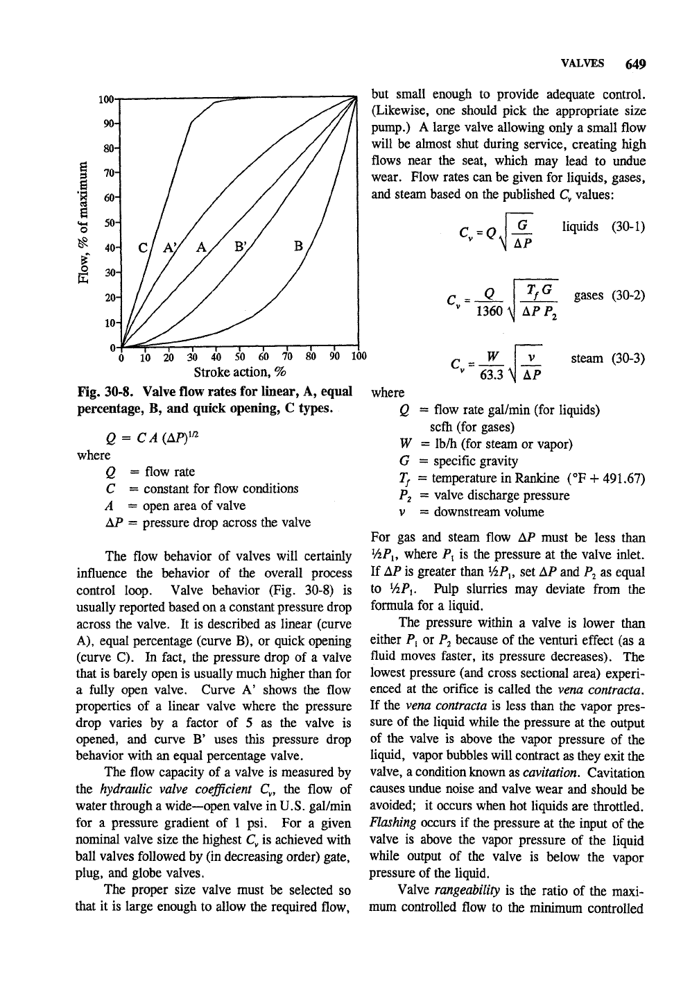
Fig. 30-8. Valve flow rates for linear, A, equal
percentage, B, and quick opening, C types.
Q = CA(APy^
where
Q = flow rate
C = constant for flow conditions
A = open area of valve
AP = pressure drop across the valve
C =
W
The flow behavior of valves will certainly
influence the behavior of the overall process
control loop. Valve behavior (Fig. 30-8) is
usually reported based on a constant pressure drop
across the valve. It is described as linear (curve
A),
equal percentage (curve B), or quick opening
(curve C). In fact, the pressure drop of a valve
that is barely open is usually much higher than for
a fully open valve. Curve A' shows the flow
properties of a linear valve where the pressure
drop varies by a factor of 5 as the valve is
opened, and curve B' uses this pressure drop
behavior with an equal percentage valve.
The flow capacity of a valve is measured by
the hydraulic valve coefficient Q, the flow of
water through a wide—open valve in
U.S.
gal/min
for a pressure gradient of 1 psi. For a given
nominal valve size the highest Q is achieved with
ball valves followed by (in decreasing order) gate,
plug, and globe valves.
The proper size valve must be selected so
that it is large enough to allow the required flow.
V
AP
63.3 \1
where
Q = flow rate gal/min (for liquids)
scfli (for gases)
W = Ib/h (for steam or vapor)
G = specific gravity
P2 = valve discharge pressure
V = downstream volume
gases (30-2)
steam (30-3)
If = temperature inRankine (°F + 491.67)
For gas and steam flow AP must be less than
ViPi, where P, is the pressure at the valve inlet.
If AP is greater than
ViP^,
set AP and Pj as equal
to
V2P1.
Pulp slurries may deviate from the
formula for a liquid.
The pressure within a valve is lower than
either P, or Pj because of the venturi effect (as a
fluid moves faster, its pressure decreases). The
lowest pressure (and cross sectional area) experi-
enced at the orifice is called the vena contracta.
If the vena contracta is less than the vapor pres-
sure of the liquid while the pressure at the output
of the valve is above the vapor pressure of the
liquid, vapor bubbles will contract as they exit the
valve, a condition known as
cavitation.
Cavitation
causes undue noise and valve wear and should be
avoided; it occurs when hot liquids are throttled.
Hashing occurs if the pressure at the input of the
valve is above the vapor pressure of the liquid
while output of the valve is below the vapor
pressure of the liquid.
Valve rangeability is the ratio of the maxi-
mum controlled flow to the minimum controlled
650 30. HYDRAULICS
gate valve
UT^T^
plug valve
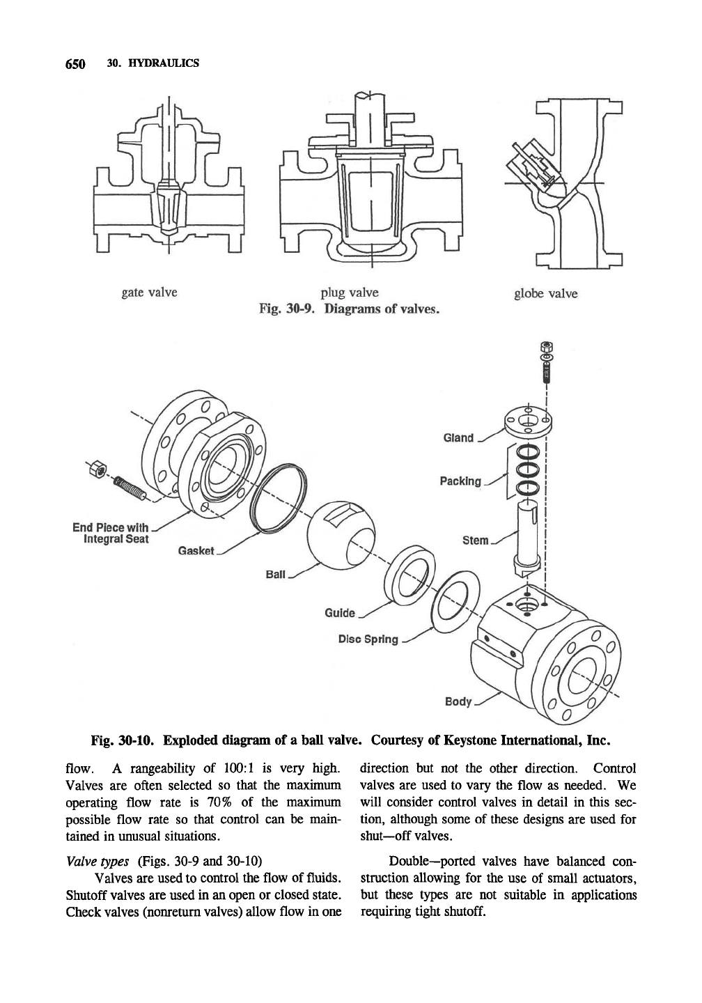
Fig. 30-9. Diagrams of valves.
globe valve
End Piece with
integral Seat
Fig. 30-10. Exploded diagram of a ball valve. Courtesy of Keystone International, Inc.
flow. A rangeability of 100:1 is very high.
Valves are often selected so that the maximum
operating flow rate is 70% of the maximum
possible flow rate so that control can be main-
tained in unusual situations.
Valve types (Figs. 30-9 and 30-10)
Valves are used to control the flow of fluids.
Shutoff valves are used in an open or closed state.
Check valves (nonreturn valves) allow flow in one
direction but not the other direction. Control
valves are used to vary the flow as needed. We
will consider control valves in detail in this sec-
tion, although some of these designs are used for
shut—off valves.
Double—ported valves have balanced con-
struction allowing for the use of small actuators,
but these types are not suitable in applications
requiring tight
shutoff.
Cast-in Top Plate
is an integral part of the
body and is standardized to
allow direct mounting of all
Keystone actuators.
Upper Stem Bushing
absorbs actuator side thrust.
Bi-Directional Stem Seal
prevents external
contamination of the stem
area and is self adjusting.
RTFE Lined Stainless Steel
Upper & Lower Stem Bearings
are isolated from the flow media
and help reduce torque.
Patented
Torque Plug Connection
offers
rigid,
high strength
engagement of disc and stem
while allowing quick and
easy disassembly.
VALVES
651
One-piece Thru-shaft Design
provides high strength and
positive disc control.
One-piece Body
allows adequate clearance for
flanges and insulation.
Disc Design
provides maximum
product flow.
Polished Disc Edge and Hubs
provide lower torques and
longer seat life.
Patented
Metal Reinforced Seat
incorporates a one-piece,
serpentine metal reinforcement
fully encapsulated within the
elastomer. This innovative seat
design reduces seating and
unseating torque and increases
sealing capabilities.
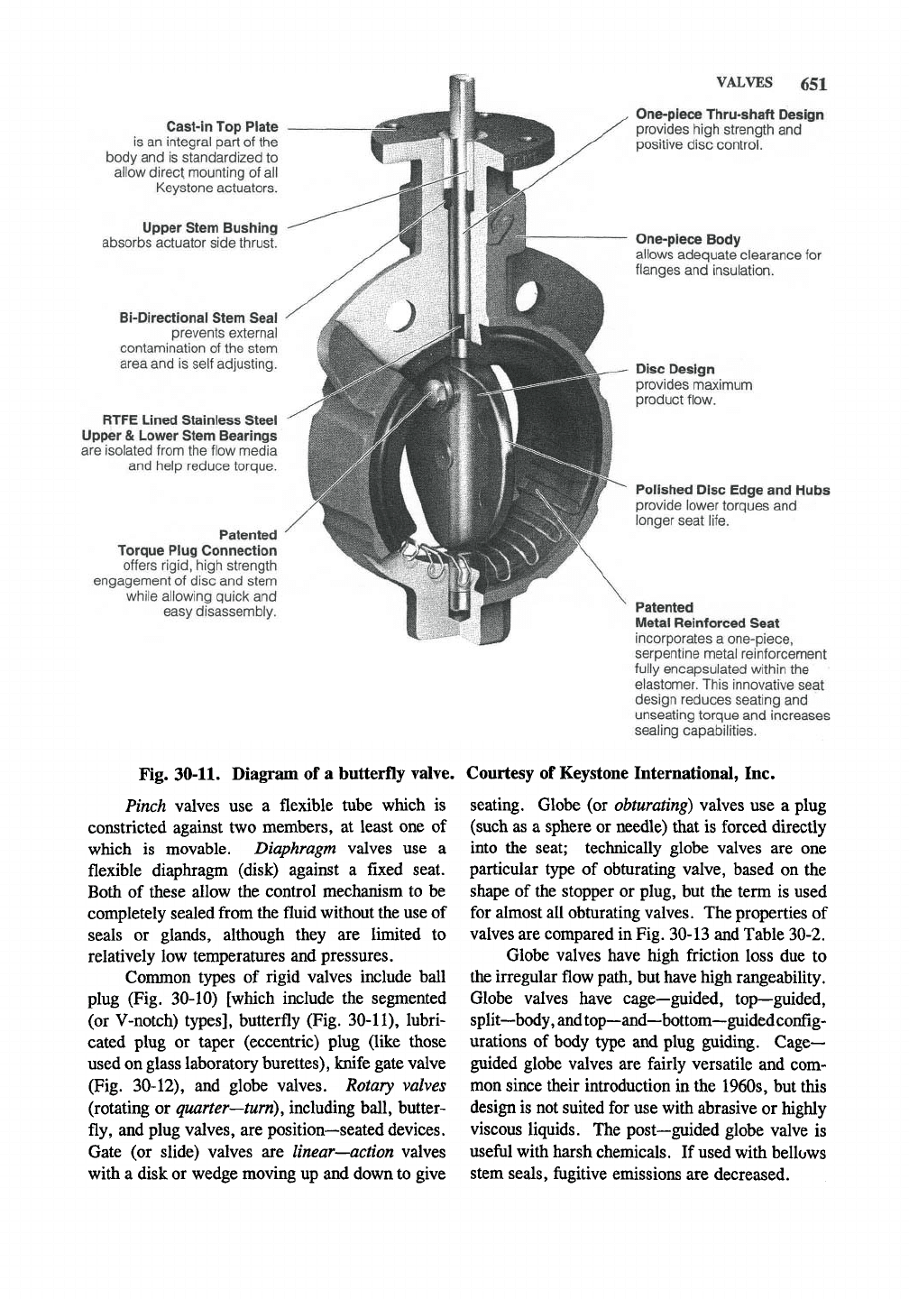
Fig.
30-11.
Diagram of a butterfly valve. Courtesy of Keystone International, Inc.
Pinch valves use a flexible tube which is
constricted against two members, at least one of
which is movable. Diaphragm valves use a
flexible diaphragm (disk) against a fixed seat.
Both of these allow the control mechanism to be
completely sealed from the fluid without the use of
seals or glands, although they are limited to
relatively low temperatures and pressures.
Conmion types of rigid valves include ball
plug (Fig. 30-10) [which include the segmented
(or V-notch) types], butterfly (Fig. 30-11), lubri-
cated plug or taper (eccentric) plug (like those
used on glass laboratory burettes), knife gate valve
(Fig. 30-12), and globe valves. Rotary valves
(rotating or quarter—turn), including ball, butter-
fly, and plug valves, are position—seated devices.
Gate (or slide) valves are linear—action valves
with a disk or wedge moving up and down to give
seating. Globe (or obturating) valves use a plug
(such as a sphere or needle) that is forced directly
into the seat; technically globe valves are one
particular type of obturating valve, based on the
shape of the stopper or plug, but the term is used
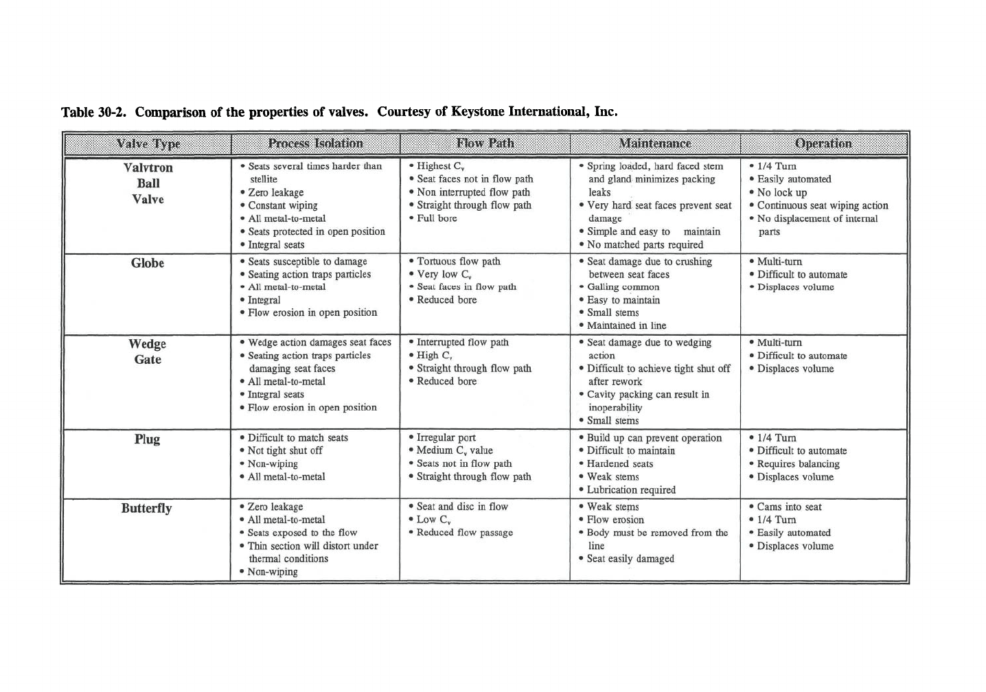
for almost all obturating valves. The properties of
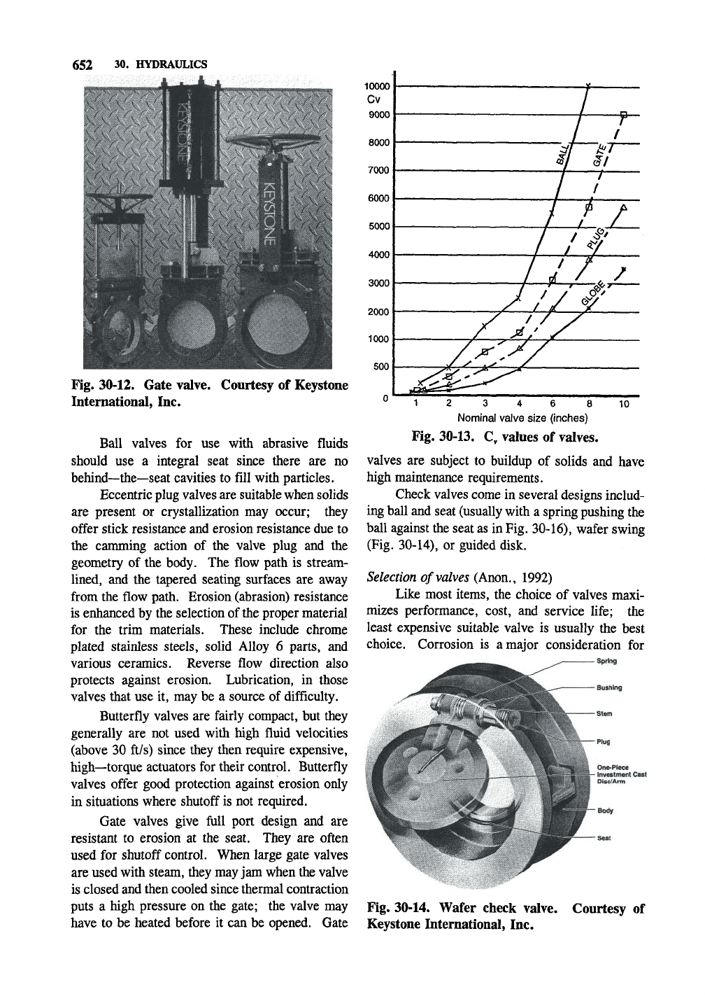
valves are compared in Fig. 30-13 and Table 30-2.
Globe valves have high friction loss due to
the irregular flow path, but have high rangeability.
Globe valves have cage—guided, top—guided,
split—body, and top—and—bottom—guidedconfig-
urations of body type and plug guiding. Cage-
guided globe valves are fairly versatile and com-
mon since their introduction in the 1960s, but this
design is not suited for use with abrasive or highly
viscous liquids. The post—guided globe valve is
useful with harsh chemicals. If used with bellows
stem seals, fugitive emissions are decreased.
652 30. HYDRAULICS
Fig. 30-12. Gate valve.
International, Inc.
Courtesy of Keystone
Ball valves for use with abrasive fluids
should use a integral seat since there are no
behind—the—seat cavities to fill with particles.
Eccentric plug valves are suitable when solids
are present or crystallization may occur; they
offer stick resistance and erosion resistance due to
the camming action of the valve plug and the
geometry of the body. The flow path is stream-
lined, and the tapered seating surfaces are away
from the flow path. Erosion (abrasion) resistance
is enhanced by the selection of the proper material
for the trim materials. These include chrome
plated stainless steels, solid Alloy 6 parts, and
various ceramics. Reverse flow direction also
protects against erosion. Lubrication, in those
valves that use it, may be a source of difficulty.
Butterfly valves are fairly compact, but they
generally are not used with high fluid velocities
(above 30 ft/s) since they then require expensive,
high—torque actuators for their control. Butterfly
valves offer good protection against erosion only
in situations where shutoff is not required.
Gate valves give full port design and are
resistant to erosion at the seat. They are often
used for shutoff control. When large gate valves
are used with steam, they may jam when the valve
is closed and then cooled since thermal contraction
puts a high pressure on the gate; the valve may
have to be heated before it can be opened. Gate
12 3 4 6 8 10
Nominal valve size (inches)
Kg.
30-13. C, values of valves.
valves are subject to buildup of solids and have
high maintenance requirements.
Check valves come in several designs includ-
ing ball and seat (usually with a spring pushing the
ball against the seat as in
Fig.
30-16), wafer swing
(Fig. 30-14), or guided disk.
Selection of
valves
(Anon,, 1992)
Like most items, the choice of valves maxi-
mizes performance, cost, and service life; the
least expensive suitable valve is usually the best
choice. Corrosion is a major consideration for
One-Piece
Investment Cast
Disc/Arm
Fig. 30-14. Wafer check valve. Courtesy of
Keystone International, Inc.
2
(g
«
QTQ
re
^
11
»
>
s:
iz:
a
s
?
::
§^
I
"
• • • • •
i
^
r
I
^
2.
3
r
§5
§•
3
p
&•
do"
3
S
§
S.
<i
^
cr
9-
25^
5-
>
00 03
Is
i
IIJ
sr
C{0
>
n
N
CJQ
J?
p g
O
r
3
£s
^
^
5 3
s-
5-1^
5'
>*
5?
<
i:^
2
S »
I
^
s.
§
^ ^
§^
I
cr
e^
5
!^
S^
!=i
o 2 o
^ ^
i
&
^
I
I
ft
S"
tJd
^ ^
lis
wj
cio
-a
?•§
-
i
3'
3
^
K
O
W
3
S^
2
c«
m
O
cr
C{p
I
^
t^'
H^
D
^
O
5 3
O
D S
o p
<
o
o p
3*
£
3 2
s
o
§
c)
^ :^
tic
|3
3
S
I
o
Ms
m
m
m