Bichop R.H. (Ed.) Mechatronic Systems, Sensors, and Actuators: Fundamentals and Modeling
Подождите немного. Документ загружается.

20-24 Mechatronic Systems, Sensors, and Actuators
the motor and magnet combination. The accuracy of the servo-type accelerometers is ultimately limited
by consistency and stability of scale factors of coupling and cup-and-magnet devices as a function of
time and temperature.
Another accelerometer based on induction design uses the eddy-current induction torque generation.
The force-generating mechanism of an induction accelerometer consists of a stable magnetic field, usually
supplied by a permanent magnet, which penetrates orthogonally through a uniform conduction sheet.
The movement of the conducting sheet relative to the magnetic field in response to acceleration results
in a generated electromotive potential in each circuit in the conductor. This action is in accordance with
Faraday’s principle. In induction-type accelerometers, the induced eddy currents are confined to the
conductor sheet, making the system essentially a drag coupling. Since angular rate is proportional to
acceleration, angular position represents change in velocity. This is a particularly useful feature in navi-
gation applications.
A typical commercial instrument based on the servo-accelerometer principle might have a microma-
chined quartz flexure suspension, differential capacitance angle pick-off, air-squeeze film plus servo-lead
compensation for system damping. Of the available models, as an example, a typical 30g unit has a
threshold and resolution of 1
µ
g, a frequency response that is flat to within 0.05% at 10 Hz and 2% at
100 Hz, a natural frequency of 1500 Hz, a damping ratio from 0.3 to 0.8, and transverse or cross-axis
sensitivity of 0.1%. If, for example, the output current is about 1.3 mA/g, a 250 Ω readout resistor would
give about ±10 V full scale at 30g. These accelerometers are good for precision work and used in many
applications such as aircraft and missile control systems, measurement of tilt angles for borehole navi-
gation, and axle angular bending in aircraft weight and balance systems.
20.2.7 Piezoelectric Accelerometers
Piezoelectric accelerometers are widely used for general-purpose acceleration, shock, and vibration mea-
surements. They are basically motion transducers with large output signals and comparatively small sizes
and they are self generators not requiring external power sources. They are available with very high
natural frequencies and are therefore suitable for high-frequency applications and shock measurements.
These devices utilize a mass in direct contact with the piezoelectric component or crystal as shown in
Figure 20.23. When a varying motion is applied to the accelerometer, the crystal experiences a varying
force excitation (F = ma), causing a proportional electric charge q to be developed across it. So,
(20.21)
where q is the charge developed and d
ij
is the piezoelectric coefficient of the material.
As this equation shows, the output from the piezoelectric material is dependent on its mechanical
properties, d
ij
. Two commonly used piezoelectric crystals are lead-zirconate titanate ceramic (PZT) and
crystalline quartz. They are both self-generating materials and produce a large electric charge for their
size. The piezoelectric strain constant of PZT is about 150 times that of quartz. As a result, PZTs are
much more sensitive and smaller in size than quartz counterparts. These accelerometers are useful for
FIGURE 20.23 A compression type piezoelectric accel-
erometer arrangement.
qd
ij
Fd
ij
ma==
Mass
PZT crystal
PZT crystal
Output
9258_C020.fm Page 24 Tuesday, October 9, 2007 9:08 PM
Sensors 20-25
high-frequency applications. The roll-off typically starts near 100 Hz. These active devices have no DC
response. Since piezoelectric accelerometers have comparatively low mechanical impedances, their effect
on the motion of most structures is negligible.
Mathematically, their transfer function approximates a third-order system that can be expressed as
(20.22)
where K
q
is the piezoelectric constant related to charge (C cm),
τ
is the time constant of the crystal, and
s is the Laplace variable. It is worth noting that the crystal itself does not have a time constant
τ
, but the
time constant is observed when the accelerometer is connected to an electric circuit, for example, an RC
circuit.
The low-frequency response is limited by the piezoelectric characteristic
τ
s/(
τ
s + 1), while the high-
frequency response is related to mechanical response. The damping factor
ζ
is very small, usually less
than 0.01 or near zero. Accurate low-frequency response requires large
τ
, which is usually achieved by
use of high-impedance voltage amplifiers. At very low frequencies thermal effects can have severe influ-
ences on the operation characteristics.
In piezoelectric accelerometers, two basic design configurations are used: compression types and shear-
stress types. In compression-type accelerometers, the crystal is held in compression by a preload element;
therefore the vibration varies the stress in compressed mode. In a shear-stress accelerometer, vibration
simply deforms the crystal in shear mode. The compression accelerometer has a relatively good mass to
sensitivity ratio and hence exhibits better performance. But, since the housing acts as an integral part of
the spring–mass system, it may produce spurious interfaces in the accelerometer output if excited around
its natural frequency.
Piezoelectric accelerometers are available in a wide range of specifications and are offered by a large
number of manufacturers. For example, the specifications of a shock accelerometer may have 0.004 pC/g
in sensitivity and a natural frequency of up to 250,000 Hz, while a unit designed for low-level seismic
measurements might have 1000 pC/g in sensitivity and only 7000 Hz natural frequency. They are man-
ufactured as small as 3 × 3 mm in dimension with about 0.5 g in mass, including cables. They have
excellent temperature ranges and some of them are designed to survive the intensive radiation environ-
ment of nuclear reactors. However, piezoelectric accelerometers tend to have larger cross-axis sensitivity
than other types, about 2–4%. In some cases, large cross-axis sensitivity may be minimized during
installations by the correct orientation of the device. These accelerometers may be mounted with threaded
studs, with cement or wax adhesives, or with magnetic holders.
20.2.8 Piezoresistive Accelerometers
Piezoresistive accelerometers are essentially semiconductor strain gauges with large gauge factors. High
gauge factors are obtained since the material resistivity is dependent primarily on the stress, not only on
the dimensions. This effect can be greatly enhanced by appropriate doping of semiconductors such as
silicon. Most piezoresistive accelerometers use two or four active gauges arranged in a Wheatstone bridge.
Extra precision resistors are used, as part of the circuit, in series with the input to control the sensitivity,
for balancing, and for offsetting temperature effects. The sensitivity of a piezoresistive sensor comes from
the elastic response of its structure and resistivity of the material. Wire and thick or thin film resistors
have low gauge factors, that is, the resistance change due to strain is small. The mechanical construction
of a piezoresistive accelerometer is shown in Figure 20.24.
Piezoresistive accelerometers are useful for acquiring vibration information at low frequencies, for exam-
ple, below 1 Hz. In fact, they are inherently true non-vibrational acceleration sensors. They generally have
wider bandwidth, smaller nonlinearities and zero shifting, and better hysteresis characteristics compared to
piezoelectric counterparts. They are suitable to measure shocks well above 100,000g. Typical characteristics
e
0
s()
as()
-----------
K
q
τ
s
C
ω
n
2
τ
s 1+()s
2
/
ω
n
2
2
ζ
s/
ω
n
1++()
--------------------------------------------------------------------------------
=
9258_C020.fm Page 25 Tuesday, October 9, 2007 9:08 PM
20-26 Mechatronic Systems, Sensors, and Actuators
of piezoresistive accelerometers may be listed to be 100 mV/g as the sensitivity, 0–750 Hz as the frequency
range, 2500 Hz in resonance frequency, 25g as the amplitude range, 2000g as the shock rating, and 0–95°C
as the temperature range, with a total mass of about 25 g.
Most contemporary piezoresistive sensors are manufactured from a single piece of silicon. This gives
better stability and less thermal mismatch between parts. In a typical monolithic sensing element a 1-mm
silicon chip incorporates the spring, mass, and four-arm bridge assembly. The elements are formed by a
pattern of dopant in the originally flat silicon. Subsequent etching of channels frees the gauges and simul-
taneously defines the masses as regions of silicon of original thickness.
20.2.9 Strain-Gauge Accelerometers
Strain-gauge accelerometers are based on resistance properties of electrical conductors. If a conductor
is stretched or compressed, its resistance alters due to (a) dimensional changes, and (b) the changes in
the fundamental property of material called piezoresistance. This indicates that the resistivity
ρ
of the
conductor depends on the mechanical strain applied onto it. The dependence is expressed as the gauge
factor:
(20.23)
where 1 indicates the resistance change due to length, 2v indicates resistance change due to area, and
(d
ρ
/
ρ
)/(dL/L) indicates the resistance change due to piezoresistivity.
There are many types of strain-gauges: unbonded metal-wire gauges, bonded metal-wire gauges,
bonded metal-foil gauges, vacuum-deposited thin-metal-film gauges, bonded semiconductor gauges, and
diffused semiconductor gauges. However, usually bonded and unbonded metal-wire gauges find wider
applications. A section of the strain-gauge accelerometers, particularly bonded semiconductor types,
known as the piezoresistive transducers, are used, but they suffer from high temperature sensitivities,
nonlinearities, and some mounting difficulties. Nevertheless, with the recent developments of microma-
chine technology, these sensors have been improved considerably, thus finding many new applications.
Unbonded-strain-gauge accelerometers use the strain wires as the spring element and as the motion
transducer, using similar arrangements as in Figure 20.25. They are useful for general-purpose motion
and vibration measurements from low to medium frequencies. They are available in wide ranges and
characteristics: typically
±
5
g
to
±
200
g
full scale, a natural frequency of 17–800 Hz, a 10-V excitation voltage
AC or DC, full scale output
±
20 to
±
50 mV, a resolution less than 0.1%, an inaccuracy less than 1% full
scale, and a cross-axis sensitivity less than 2%. The damping ratio (using silicone oil damping) is 0.6–0.8
at room temperature. These instruments are small and light, usually with a mass less than 25 g.
FIGURE 20.24 Bonding of piezoresistive and piezoelectric accelerometers to the inertial systems.
Compression
gauges
Seismic
mass
Tension
gauges
+
dR/R
dL/L
-------------
12v
d
ρ
/
ρ
dL/L
------------
++=
9258_C020.fm Page 26 Tuesday, October 9, 2007 9:08 PM
Sensors 20-27
Bonded-strain-gauge accelerometers generally use a mass supported by a thin flexure beam. The strain-
gauges are cemented onto the beam to achieve maximum sensitivity, temperature compensation, and
sensitivity to both cross-axis and angular accelerations. Their characteristics are similar to the unbonded-
strain-gauge accelerometers but have greater sizes and weights. Often silicone oil is used for damping.
Semiconductor strain gauges are widely used as strain sensors in cantilever-beams and mass types of accel-
erometers. They allow high outputs (0.2–0.5 V full scale). Typically, a ±25g acceleration unit has a flat
response from 0 to 750 Hz, a damping ratio of 0.7, a mass of about 28 g, and an operational temperature
of −18°C to +93°C. A triaxial ±20,000g model has a flat response from 0 to 15 kHz, a damping ratio
of 0.01, and a compensation temperature range of 0–45°C, and is 13 × 10 × 13 mm
3
in size and 10 g
in mass.
20.2.10 Electrostatic Accelerometers
Electrostatic accelerometers are based on Coulomb’s law between two charged electrodes; therefore, they
are capacitive types. Depending on the operation principles and external circuits they can be broadly
classified as (a) electrostatic-force-feedback accelerometers, and (b) differential-capacitance accelerometers.
20.2.10.1 Electrostatic-Force-Feedback Accelerometers
An electrostatic-force-feedback accelerometer consists of an electrode, with mass m and area S, mounted
on a light pivoted arm that moves relative to some fixed electrodes. The nominal gap h between the
pivoted and fixed electrodes is maintained by means of a force-balancing servo system, which is capable of
varying the electrode potential in response to signals from a pickoff mechanism that senses relative
changes in the gap. Mathematically, the field between the electrodes may be expressed by
(20.24)
where E is the intensity or potential gradient (dV/dx), Q is the charge, S is the area of the conductor, and
k is the dielectric constant of the space outside the conductor.
From this expression, it can be shown that the force per unit area of the charged conductor (in N/m
2
)
is given by
(20.25)
Consider one movable and one stationary electrode and assume that the movable electrode is main-
tained at a bias potential V
1
and the stationary one at a potential V
2
. The electrical intensity E in the gap,
h, can be expressed as
(20.26)
so that the force of attraction may be found as
(20.27)
In the presence of acceleration, if V
2
is adjusted to restrain the movable electrode to the null position,
the expression relating acceleration and electrical potential may be given by
(20.28)
E
Q
ε
kS
--------
=
F
S
---
Q
2
2
ε
kS
2
--------------
ε
kE
2
2
-----------
==
E
1
V
1
V
2
–
h
-----------------
=
F
1
ε
kE
2
S
2h
2
--------------
ε
kV
1
V
2
–()
2
S
2h
2
----------------------------------
==
a
F
1
m
-----
ε
kV
1
V
2
–()
2
S
2h
2
m
----------------------------------
==
9258_C020.fm Page 27 Tuesday, October 9, 2007 9:08 PM

20-28 Mechatronic Systems, Sensors, and Actuators
The device so far described can measure acceleration in one direction only, and the output is quadratic
in character, that is,
(20.29)
where D is the constant of proportionality.
The output may be linearized in a number of ways, one of which is the quarter-square method. If the
servo controller applies a potential −V
2
to the other fixed electrode, the force of attraction between this
electrode and the movable electrode becomes
(20.30)
and the force-balance equation of the movable electrode when the instrument experiences a downward
acceleration a now is
or
(20.31)
Hence, if the bias potential V
1
is held constant and the gain of the control loop is high so that variations
in the gap are negligible, the acceleration becomes a linear function of the controller output voltage V
2
.
The principal difficulty in mechanizing the electrostatic force accelerometer is the relatively high
electric field intensity required to obtain an adequate force. Damping can be provided electrically or by
viscosity of the gaseous atmosphere in the inter-electrode space if the gap h is sufficiently small. The
scheme works best in micromachined instruments. Nonlinearity in the voltage breakdown phenomenon
permits larger gradients in very small gaps.
A typical electrostatic accelerometer has the following characteristics: range ±50g, resolution 10
−3
g,
sensitivity 100 mV/g, nonlinearity <1% FS, transverse sensitivity <1% FS, thermal sensitivity 6 × 10
−4
/K,
mechanical shock 10,000g, operating temperature −45°C to 90°C, supply voltage 5 V DC, and weight
45 g. The main advantages of electrostatic accelerometers are their extreme mechanical simplicity, low
power requirements, absence of inherent sources of hysteresis errors, zero temperature coefficients, and
ease of shielding from stray fields.
20.2.10.2 Differential-Capacitance Accelerometers
Differential-capacitance accelerometers are based on the principle of the change of capacitance in pro-
portion to applied acceleration. In one type, the seismic mass of the accelerometer is made as the movable
element of an electrical oscillator. The seismic mass is supported by a resilient parallel-motion beam
arrangement from the base. The system is set to have a certain defined nominal frequency when undis-
turbed. If the instrument is accelerated, the frequency varies above and below the nominal value depend-
ing on the direction of acceleration.
The seismic mass carries an electrode located in opposition to a number of base-fixed electrodes that
define variable capacitors. The base-fixed electrodes are resistances coupled in the feedback path of a
wideband, phase-inverting amplifier. The gain of the amplifier is predetermined to ensure maintenance
V
1
V
2
–()Da=
a
F
2
m
-----
ε
kV
1
V
2
+()
2
S
2h
2
m
----------------------------------
==
ma F
2
F
1
–
ε
kS V
1
V
2
+()
2
V
1
V
2
–()
2
–[]
2h
2
---------------------------------------------------------------------
==
ma F
2
F
1
–
2
ε
kSV
1
V
2
h
2
------------------------
==
9258_C020.fm Page 28 Tuesday, October 9, 2007 9:08 PM
Sensors 20-29
of oscillations over the range of variation of the capacitance determined by the applied acceleration. The
value of the capacitance C for each of the variable capacitors is given by
(20.32)
where k is the dielectric constant,
ε
is the permittivity of free space, S is the area of the electrode, and
h is the variable gap.
Denoting the magnitude of the gap for zero acceleration as h
0
, the value of h in the presence of
acceleration a may be written as
(20.33)
where m is the value of the proof mass and K is the spring constant. Thus,
(20.34)
For example, the frequency of oscillation of the resistance–capacitance type circuit is given by the expression
(20.35)
Substituting this value of C in Equation 20.34 gives
(20.36)
Denote the constant quantity as B and rewrite Equation 20.36 as
(20.37)
The first term on the right-hand side expresses the fixed bias frequency f
0
and the second term denotes
the change in frequency resulting from acceleration, so that the expression may be written as
(20.38)
If the output frequency is compared with an independent source of a constant frequency of f
0
, then f
a
can be determined easily.
A commonly used capacitive-type accelerometer is based on a thin diaphragm with spiral flexures that
provide the spring, proof mass, and moving plate necessary for the differential capacitor. Plate motion
between the electrodes pumps air parallel to the plate surface and through holes in the plate to provide
squeeze film damping. Since air viscosity is less temperature sensitive than oil, the desired damping ratio
of 0.7 hardly changes more than 15%. A family of such instruments are easily available with full-scale
ranges from ±0.2g (4 Hz flat response) to ±1000g (3000 Hz), a cross-axis sensitivity less than 1%, and a
full-scale output of ±1.5 V. The size of a typical device is about 25 mm
3
with a mass of 50 g.
C
ε
kS
h
--------
=
hh
0
ma
K
-------
+=
C
ε
kS
h
0
ma/K()+
------------------------------
=
f
6
2
π
RC
--------------
=
f
6 h
0
ma/K()+[]
2
π
R
ε
kS
------------------------------------------
=
6/(2
π
R
ε
kS)
fBh
0
Bma
K
-----------+=
ff
0
f
a
+=
9258_C020.fm Page 29 Tuesday, October 9, 2007 9:08 PM
20-30 Mechatronic Systems, Sensors, and Actuators
20.2.11 Micro- and Nanoaccelerometers
By the end of the 1970s it became apparent that the essentially planar processing integrated-circuit (IC)
technology could be modified to fabricate three-dimensional electromechanical structures by the micro-
machining process. Accelerometers and pressure sensors were among the first IC sensors. The first
accelerometer was developed in 1979. Since then the technology has been progressing steadily and now
an extremely diverse range of accelerometers are readily available. Most sensors use bulk micromachining
rather than surface micromachining techniques. In bulk micromachining the flexures, resonant beams,
and all other critical components of the accelerometer are made from bulk silicon in order to exploit the
full mechanical properties of silicon crystals. With proper design and film process, bulk micromachining
yields extremely stable and robust accelerometers.
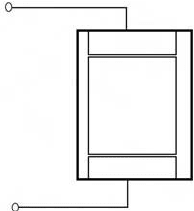
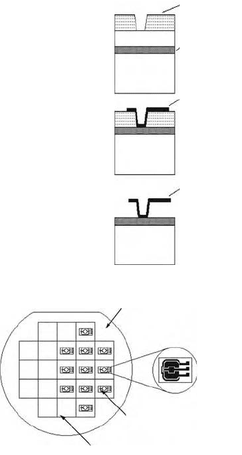
The selective etching of multiple layers of deposited thin films, or surface micromachining, allows
movable microstructures to be fabricated on silicon wafers. With surface micromachining, layers of
structure material are disposed and patterned as shown in Figure 20.25. These structures are formed by
polysilicons and sacrificial materials such as silicon dioxides. The sacrificial material acts as an intermediate
spacer layer and is etched away to produce a freestanding structure. Surface machining technology also
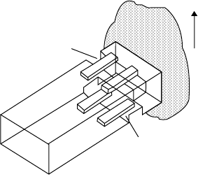
allows smaller and more complex structures to be built in multiple layers on a single substrate. A typical
example of modern micromachined accelerometer is given in Figure 20.26. Multiple accelerometers can
be mounted on a single chip, sensing accelerations in
x
,
y
, and
z
directions. The primary signal condi-
tioning is also provided in the same chip. The output from the chip is usually read in the digital form.
FIGURE 20.25 Steps of micromachining to manufac-
ture micro- and nanoaccelerometers.
FIGURE 20.26 Multiple accelerometers in a single chip.
Substrate
Substrate
Substrate
Freestanding
micromechanical
structure
Spacer
layer
Body
layer
Isolation
layer
Sawin
g
lines
Individual
accelerometer
Silicon
wafer
9258_C020.fm Page 30 Tuesday, October 9, 2007 9:08 PM
Sensors 20-31
Most micro- and nanoaccelerometers detect acceleration by measuring the relative motion between
proof mass and mounting substrate. The proof mass is suspended above the substrate by a mechanical
spring suspension. When the sensor undergoes acceleration, the proof mass tends to remain stationary
and therefore displaces with respect to the moving substrate. This displacement is measured capacitively
or by means of piezoresistive or piezoelectric methods using CMOS technology. Chip circuits provide
offset cancellation for bias stability, gain scale factor stability, zero acceleration bias stability, temperature
compensation, prefiltering, noise immune digital output, and so on.
The operational principles of some of the microaccelerometers are very similar to capacitive force-
balance or vibrating-beam accelerometers, discussed earlier. Manufacturing techniques may change from
one manufacturer to another. However, in general, vibrating-beam accelerometers are preferred because
of better air-gap properties and improved bias performance characteristics.
Vibrating-beam accelerometers, also termed resonant-beam force transducers, are made in such a way
that an acceleration along a positive input axis places the vibrating beam in tension. Thus, the resonant
frequency of the vibrating beam increases or decreases with the applied acceleration.
In DETF, an electronic oscillator capacitively couples energy into two vibrating beams to keep them
oscillating at their resonant frequency. The beams vibrate 180° out of phase to cancel reaction forces at the
ends. The dynamic cancellation effect of the DETF design prevents energy from being lost through the
ends of the beam. Hence, the dynamically balanced DETF resonator has a high Q factor, which leads to a
stable oscillator circuit. The acceleration signal is produced from the oscillator as a frequency-modulated
square wave that can be used for a digital interface.
The frequency of resonance of the system must be much higher than any input acceleration, and this
limits the measurable range. In a micromachined accelerometer, used in military applications, the fol-
lowing characteristics are given: a range of ±1200g, a sensitivity of 1.11 Hz/g, a bandwidth of 2500 Hz,
an unloaded DETF frequency of 9952 Hz. The frequency at +1200g is 11,221 Hz, the frequency at –1200g
is 8544 Hz, and the temperature sensitivity is 5 mg/°C. The accelerometer size is 6 mm diameter by
4.3 mm length, with a mass of about 9 g. It has a turn-on time of less than 60 s, the accelerometer is
powered with +9 to +16 V DC, and the nominal output is a 9000-Hz square wave.
Surface micromachining has also been used to manufacture specific application accelerometers, such
as air-bag applications in the automotive industry. In one type, a three-layer differential capacitor is
created by alternate layers of polysilicon and phosphosilicate glass (PSG) on a 0.38-mm thick, 100-mm
long wafer. A silicon wafer serves as the substrate for the mechanical structure. The trampoline-shaped
middle layer is suspended by four supporting arms. This movable structure is the seismic mass for the
accelerometer. The upper and lower polysilicon layers are fixed plates for the differential capacitors. The
glass is sacrificially etched by hydrofluoric acid (HF).
20.2.12 Signal Conditioning and Biasing
Common signal conditioners are appropriate for interfacing accelerometers to computers or other instru-
ments for further signal processing. Generally, the generated raw signals are amplified and filtered suitably
by the circuits within the accelerometer casing supplied by manufacturers. Nevertheless, piezoelectric
and piezoresistive transducers require special signal conditioners with certain characteristics that will be
discussed next.
20.2.12.1 Piezoelectric Accelerometers
Piezoelectric accelerometers supply small energy to the signal conditioners since they have high capacitive
source impedances. The equivalent circuit of a piezoelectric accelerometer can be regarded as an active
capacitor that charges itself when mechanically loaded. The selection of the elements of the external
signal conditioning circuit is dependent on the characteristics of the equivalent circuit. A most common
approach is the charge amplifier since the system gain and low-frequency responses of these amplifiers
are well defined. The performance of the circuit is also independent of cable length and capacitance of
the accelerometer. In many applications, noise-treated cables are necessary to avoid the triboelectric
charges occurring due to movement of cables.
9258_C020.fm Page 31 Tuesday, October 9, 2007 9:08 PM
20-32 Mechatronic Systems, Sensors, and Actuators
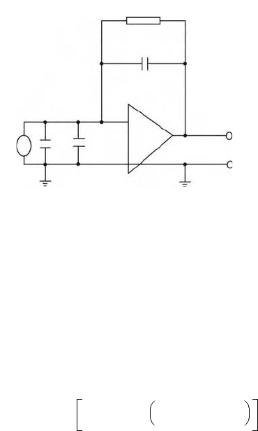
The charge amplifier (with about 1000 MΩ input impedance) basically converts the input charge to
voltage first and then amplifies this voltage. It consists of a charge converter output voltage, which occurs
as a result of the charge input signal returning through the feedback capacitor to maintain the input
voltage at the input level close to zero, as shown in Figure 20.27. With the help of basic operational-type
feedback, the amplifier input is maintained at essentially 0 V; therefore, it looks like a short circuit to
the input. Thus, the charge input is stored in the feedback capacitor, producing a voltage across it that
is equal to the value of the charge input divided by the capacitance of the feedback capacitor. The complete
transfer function of the circuit describing the relationship between the output voltage and the input
acceleration magnitude may be determined by the following complex transform:
(20.39)
where E
0
is the charge converter output (V), a
0
is the magnitude of acceleration (m/s
2
), S
a
is the accel-
erometer sensitivity (mV/g), C
a
is the accelerometer capacitance (F), C
c
is the cable capacitance (F), C
f
is the feedback capacitance (F), R
f
is the feedback loop resistance, and G is the amplifier open-loop gain.
In most applications, since C
f
is selected to be large compared to (C
a
+ C
c
)/(1 + G), the system gain
becomes independent of the cable length. In this case the denominator of the equation can be simplified
to give a first-order system with roll off at
(20.40)
with a slope of 10 dB per decade. For practical purposes, the low-frequency response of this system is a
function of well-defined electronic components and does not vary by cable length. This is an important
feature when measuring low-frequency vibrations.
Many piezoelectric accelerometers are manufactured with preamplifiers and other signal-conditioning
circuits enclosed in the same casing. Some accelerometer preamplifiers include integrators to convert the
acceleration proportional outputs to either velocity or displacement proportional signals. To attenuate
noise and vibration signals that lie outside the frequency range of interest, most preamplifiers are
equipped with a range of high- and low-pass filters. This avoids interference from electrical noise or
signals inside the linear portion of the accelerometer frequency range. Nevertheless, it is worth mentioning
that these devices usually have two time constants, external and internal. The mixture of these two time
constants can lead to problems particularly at low frequencies. Manufacturers through design and
construction usually fix the internal time constants. However, care must be observed to account for the
effect of external time constants through impedance matching.
FIGURE 20.27 A typical charge amplifier.
E
0
C
c
–A
C
f
R
f
Q
s
Cable
C
a
~
~
Transducer
Charge amplifier
E
0
a
0
-----
S
a
jR
f
C
f
ω
1 jR
f
C
f
ω
1 C
f
C
a
C
c
+
1 G+
-----------------
++
+=
f
−3dB
1
2
π
R
e
C
f
-----------------
=
9258_C020.fm Page 32 Tuesday, October 9, 2007 9:08 PM
Sensors 20-33
20.2.12.2 Piezoresistive Transducers
Piezoresistive transducers generally have high-amplitude outputs, low-output impedance, and low intrin-
sic noise. Most of these transducers are designed for constant-voltage excitations. They are usually
calibrated for constant-current excitations to avoid external interference. Many piezoresistive transducers
are configured as full-bridge devices. Some have four active piezoresistive arms, together with two fixed
precision resistors to permit shunt calibration.
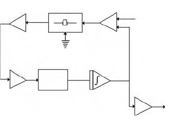
20.2.12.3 Microaccelerometers
In microaccelerometers signal-conditioning circuitry is integrated within the same chip as the sensor. A
typical example of the signal-conditioning circuitry is given in Figure 20.28 in block diagram form. In
this type of accelerometer, the electronic system is essentially a crystal-controlled oscillator circuit and
the output signal of the oscillator is a frequency-modulated acceleration signal. Some circuits provide a
buffered square-wave output that can be directly interfaced digitally. In these cases the need for analog-
to-digital (A/D) conversion is eliminated, thus removing one of the major sources of errors. In other
types of accelerometers, signal conditioning circuits such as A/D converters are retained within the chip.
20.2.12.4 Force Feedback Accelerometers
Signals from force feedback accelerometers often must be digitized for use in digital systems. A common
solution is to use voltage to frequency or current to frequency converters to convert the analog signals
to train pulses. These converters are expensive, often as much as the accelerometer, and add as much to
the error budget.
Here, it is worth mentioning that GPS systems are becoming add-ons to many position sensing
mechanisms. Because of antenna dynamics, shadowing, multipath effects, and to provide redundancy
for critical systems such as aircraft, many of these systems require inertial aiding, tied-in with accelerom-
eters and gyros. With the development of micromachining, small and cost-effective GPS assisted inertial
systems will be available in the near future. These developments will require extensive signal processing
with a high degree of accuracy. Dynamic ranges on the order of a million to one (e.g., 30–32 bits) need
to be dealt with. In order to achieve accuracy requirements, a great challenge awaits the signal processing
practitioner.
References
1. Bentley, J. P., Principles of Measurement Systems, 2nd ed., Burnt Mill, UK: Longman Scientific and
Technical, 1988.
2. Doebelin, E. O., Measurement Systems: Application and Design, 4th ed., Singapore: McGraw-Hill, 1990.
3. Frank, R., Understanding Smart Sensors, Boston: Artech House, 1996.
4. Harris, C., Shock and Vibration Handbook, 4th ed., McGraw-Hill, 1995.
5. Holman, J. P., Experimental Methods for Engineers, 5th ed., Singapore: McGraw-Hill, 1989.
FIGURE 20.28 A typical signal conditioning arrangement for single chip microaccelerometers.
Gain block
Output
Substrate
Solid state
accelerometer
Matching amp
V bias
Bias amp
Buffer
Limiter
Bandpass
filter
9258_C020.fm Page 33 Tuesday, October 9, 2007 9:08 PM