Bichop R.H. (Ed.) Mechatronic Systems, Sensors, and Actuators: Fundamentals and Modeling
Подождите немного. Документ загружается.

11-16 Mechatronic Systems, Sensors, and Actuators
Once each branch current is defined in terms of the node voltages, Kirchhoff’s current law is applied
at each node. The particular form of KCL employed in the nodal analysis equates the sum of the currents
into the node to the sum of the currents leaving the node:
(11.24)
Figure 11.23 illustrates this procedure.
The systematic application of this method to a circuit with n nodes would lead to writing n linear
equations. However, one of the node voltages is the reference voltage and is therefore already known,
since it is usually assumed to be zero. Thus, we can write n – 1 independent linear equations in the n – 1
independent variables (the node voltages). Nodal analysis provides the minimum number of equations
required to solve the circuit, since any branch voltage or current may be determined from knowledge of
nodal voltages.
The nodal analysis method may also be defined as a sequence of steps, as outlined below.
11.3.1.1 Node Voltage Analysis Method
1. Select a reference node (usually ground). All other node voltages will be referenced to this node.
2. Define the remaining n – 1 node voltages as the independent variables.
3. Apply KCL at each of the n – 1 nodes, expressing each current in terms of the adjacent node
voltages.
4. Solve the linear system of n – 1 equations in n – 1 unknowns.
In a circuit containing n nodes we can write at most n – 1 independent equations.
11.3.2 The Mesh Current Method
In the mesh current method, we observe that a current flowing through a resistor in a specified direction
defines the polarity of the voltage across the resistor, as illustrated in Figure 11.24, and that the sum of
the voltages around a closed circuit must equal zero, by KVL. Once a convention is established regarding
the direction of current flow around a mesh, simple application of KVL provides the desired equation.
Figure 11.25 illustrates this point.
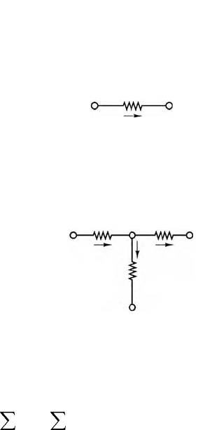
FIGURE 11.22 Branch current formulation in nodal
analysis.
FIGURE 11.23 Use of KCL in nodal analysis.
In the node voltage method, we
assign the node voltages v
a
and v
b
;
the branch current flowing from a
to b is then expressed in the terms of
these node voltages.
v
a
– v
b
R
i =
______
v
a
v
b
R
i
v
a
– v
b
R
1
______
=
v
b
– v
c
R
2
______
+
v
b
– v
d
R
3
______
v
a
v
d
v
c
v
b
i
1
i
2
i
3
R
3
By KCL: i
1
= i
2
+ i
3
. In the node
voltage method, we express KCL by
R
1
R
2
i
in
i
out
=
9258_C011.fm Page 16 Tuesday, October 2, 2007 4:18 AM
Electrical Engineering 11-17
The number of equations one obtains by this technique is equal to the number of meshes in the circuit.
All branch currents and voltages may subsequently be obtained from the mesh currents, as will presently
be shown. Since meshes are easily identified in a circuit, this method provides a very efficient and sys-
tematic procedure for the analysis of electrical circuits. The following section outlines the procedure used
in applying the mesh current method to a linear circuit.
11.3.2.1 Mesh Current Analysis Method
1. Define each mesh current consistently. We shall always define mesh currents clockwise, for
convenience.
2. Apply KVL around each mesh, expressing each voltage in terms of one or more mesh currents.
3. Solve the resulting linear system of equations with mesh currents as the independent variables.
In mesh analysis, it is important to be consistent in choosing the direction of current flow. To avoid
confusion in writing the circuit equations, mesh currents will be defined exclusively clockwise when we
are using this method.
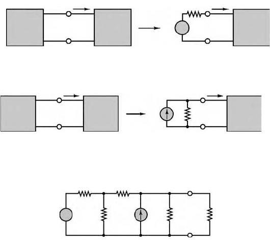
11.3.3 One-Port Networks and Equivalent Circuits
This general circuit representation is shown in Figure 11.26. This configuration is called a one-port
network and is particularly useful for introducing the notion of equivalent circuits. Note that the
network of Figure 11.26 is completely described by its i–v characteristic.
11.3.3.1 Thévenin and Norton Equivalent Circuits
This section discusses one of the most important topics in the analysis of electrical circuits: the concept
of an equivalent circuit. It will be shown that it is always possible to view even a very complicated circuit
in terms of much simpler equivalent source and load circuits, and that the transformations leading to
equivalent circuits are easily managed, with a little practice. In studying node voltage and mesh current
analysis, you may have observed that there is a certain correspondence (called duality) between current
sources and voltage sources, on the one hand, and parallel and series circuits, on the other. This duality
appears again very clearly in the analysis of equivalent circuits: it will shortly be shown that equivalent
circuits fall into one of two classes, involving either voltage or current sources and (respectively) either
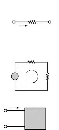
FIGURE 11.24 Basic principle of mesh analysis.
FIGURE 11.25 Use of KVL in mesh analysis.
FIGURE 11.26 One-port network.
R
v
R
The current i, defined as flowing
from left to right, establishes the
polarity of the voltage across R.
–
+
i
v
2
A mesh
Once the direction of current flow
has been selected, KVL requires
that v
1
= v
2
+ v
3.
v
1
R
2
R
3
v
3
–
+
–
+
–
+
i
Linear
network
–
+
i
v
9258_C011.fm Page 17 Tuesday, October 2, 2007 4:18 AM
11-18 Mechatronic Systems, Sensors, and Actuators
series or parallel resistors, reflecting this same principle of duality. The discussion of equivalent circuits
begins with the statement of two very important theorems, summarized in Figures 11.27 and 11.28.
The Thévenin Theorem
As far as a load is concerned, any network composed of ideal voltage and current sources, and of linear
resistors, may be represented by an equivalent circuit consisting of an ideal voltage source, v
T
, in series
with an equivalent resistance, R
T
.
The Norton Theorem
As far as a load is concerned, any network composed of ideal voltage and current sources, and of linear
resistors, may be represented by an equivalent circuit consisting of an ideal current source, i
N
, in parallel
with an equivalent resistance, R
N
.
11.3.3.2 Determination of Norton or Thévenin Equivalent Resistance
The first step in computing a Thévenin or Norton equivalent circuit consists of finding the equivalent
resistance presented by the circuit at its terminals. This is done by setting all sources in the circuit equal
to zero and computing the effective resistance between terminals. The voltage and current sources present
in the circuit are set to zero as follows: voltage sources are replaced by short circuits, current sources by
open circuits. We can produce a set of simple rules as an aid in the computation of the Thévenin (or
Norton) equivalent resistance for a linear resistive circuit.
Computation of Equivalent Resistance of a One-Port Network:
1. Remove the load.
2. Zero all voltage and current sources.
3. Compute the total resistance between load terminals, with the load removed. This resistance is
equivalent to that which would be encountered by a current source connected to the circuit in
place of the load.
For example, the equivalent resistance of the circuit of Figure 11.29 as seen by the load is:
R
eq
= ((2||2) + 1) ||2 = 1 Ω
FIGURE 11.27 Illustration of Thévenin theorem.
FIGURE 11.28 Illustration of Norton theorem.
FIGURE 11.29 Computation of Thévenin resistance.
Source Load Load
ii
v
v
T
R
T
–
+
v
–
+
–
+
Source Load
Load
ii
i
N
R
N
v
–
+
v
–
+
2 Ω 1 Ω
2 Ω5 V 2 Ω R
L
1 A
a
b
+
−
9258_C011.fm Page 18 Tuesday, October 2, 2007 4:18 AM
Electrical Engineering 11-19
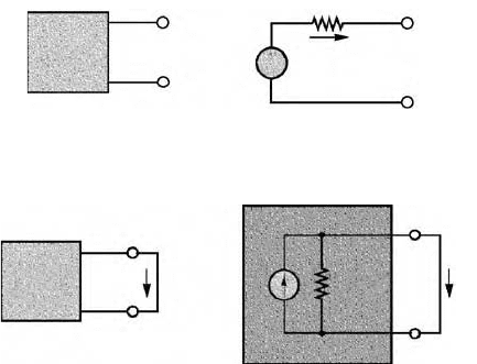
11.3.3.3 Computing the Thévenin Voltage
The Thévenin equivalent voltage is defined as follows: the equivalent (Thévenin) source voltage is equal
to the open-circuit voltage present at the load terminals with the load removed.
This states that in order to compute v
T
, it is sufficient to remove the load and to compute the open-
circuit voltage at the one-port terminals. Figure 11.30 illustrates that the open-circuit voltage, v
OC
, and the
Thévenin voltage, v
T
, must be the same if the Thévenin theorem is to hold. This is true because in the circuit
consisting of v
T
and R
T
, the voltage v
OC
must equal v
T
, since no current flows through R
T
and therefore the
voltage across R
T
is zero. Kirchhoff ’s voltage law confirms that
(11.25)
11.3.3.4 Computing the Norton Current
The computation of the Norton equivalent current is very similar in concept to that of the Thévenin
voltage. The following definition will serve as a starting point.
Definition
The Norton equivalent current is equal to the short-circuit current that would flow were the load
replaced by a short circuit.
An explanation for the definition of the Norton current is easily found by considering, again, an
arbitrary one-port network, as shown in Figure 11.31, where the one-port network is shown together
with its Norton equivalent circuit.
It should be clear that the current, i
SC
, flowing through the short circuit replacing the load is exactly
the Norton current, i
N
, since all of the source current in the circuit of Figure 11.31 must flow through
the short circuit.
11.3.3.5 Experimental Determination of Thévenin and Norton Equivalents
Figure 11.32 illustrates the measurement of the open-circuit voltage and short-circuit current for an
arbitrary network connected to any load and also illustrates that the procedure requires some special
attention, because of the nonideal nature of any practical measuring instrument. The figure clearly
illustrates that in the presence of finite meter resistance, r
m
, one must take this quantity into account in
the computation of the short-circuit current and open-circuit voltage; v
OC
and i
SC
appear between quotation
marks in the figure specifically to illustrate that the measured “open-circuit voltage” and “short-circuit
current” are, in fact, affected by the internal resistance of the measuring instrument and are not the true
quantities.
FIGURE 11.30 Equivalence of open-circuit and Thévenin voltage.
FIGURE 11.31 Illustration of Norton equivalent circuit.
i = 0
R
T
v
T
v
oc
v
oc
= v
T
One-port
network
–
–
+
+
–
+
R
T
= R
N
i
SC
i
N
i
SC
One-port
network
v
T
R
T
0() v
OC
+ v
OC
==
9258_C011.fm Page 19 Tuesday, October 2, 2007 4:18 AM
11-20 Mechatronic Systems, Sensors, and Actuators
The following are expressions for the true short-circuit current and open-circuit voltage.
(11.26)
where i
N
is the ideal Norton current, v
T
the Thévenin voltage, and R
T
the true Thévenin resistance.
11.3.4 Nonlinear Circuit Elements
11.3.4.1 Description of Nonlinear Elements
There are a number of useful cases in which a simple functional relationship exists between voltage and
current in a nonlinear circuit element. For example, Figure 11.33 depicts an element with an exponential
i–v characteristic, described by the following equations:
(11.27)
FIGURE 11.32 Measurement of open-circuit voltage and short-circuit current.
FIGURE 11.33 i–v characteristic of exponential resistor.
Unknown
network
Network connected for measurement of short-circuit current
Network connected for measurement of open-circuit voltage
An unknown network connected to a load
Load
A
V
r
m
r
m
Unknown
network
Unknown
network
“i
sc
”
“v
sc
”
–
+
a
a
a
b
b
b
-1 1
1
1.5
2
-0.5 0.5
0.5
0
Volts
Amperes
0
i
N
i
SC
1
r
m
R
T
------
+
=
v
T
v
OC
1
R
T
r
m
------
+
=
iI
0
e
α
v
, v 0>=
iI
0
, v ≤ 0–=
9258_C011.fm Page 20 Tuesday, October 2, 2007 4:18 AM
Electrical Engineering 11-21
There exists, in fact, a circuit element (the semiconductor diode) that very nearly satisfies this simple
relationship. The difficulty in the i–v relationship of Equation 11.27 is that it is not possible, in general,
to obtain a closed-form analytical solution, even for a very simple circuit.
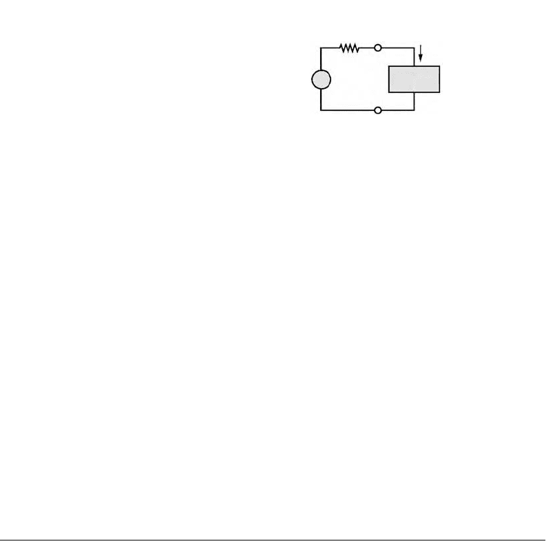
One approach to analyzing a circuit containing a nonlinear element might be to treat the nonlinear element
as a load, and to compute the Thévenin equivalent of the remaining circuit, as shown in Figure 11.34.
Applying KVL, the following equation may then be obtained:
(11.28)
To obtain the second equation needed to solve for both the unknown voltage, v
x
, and the unknown
current, i
x
, it is necessary to resort to the i-v description of the nonlinear element, namely, Equation
11.27. If, for the moment, only positive voltages are considered, the circuit is completely described by
the following system:
(11.29)
The two parts of Equation 11.29 represent a system of two equations in two unknowns. Any numerical
method of choice may now be applied to solve the system of Equations 11.29.
11.4 AC Network Analysis
In this section we introduce energy-storage elements, dynamic circuits, and the analysis of circuits excited
by sinusoidal voltages and currents. Sinusoidal (or AC) signals constitute the most important class of
signals in the analysis of electrical circuits. The simplest reason is that virtually all of the electric power
used in households and industries comes in the form of sinusoidal voltages and currents.
11.4.1 Energy-Storage (Dynamic) Circuit Elements
The ideal resistor was introduced through Ohm’s law in Section 11.2 as a useful idealization of many
practical electrical devices. However, in addition to resistance to the flow of electric current, which is purely
a dissipative (i.e., an energy-loss) phenomenon, electric devices may also exhibit energy-storage properties,
much in the same way a spring or a flywheel can store mechanical energy. Two distinct mechanisms for
energy storage exist in electric circuits: capacitance and inductance, both of which lead to the storage of
energy in an electromagnetic field.
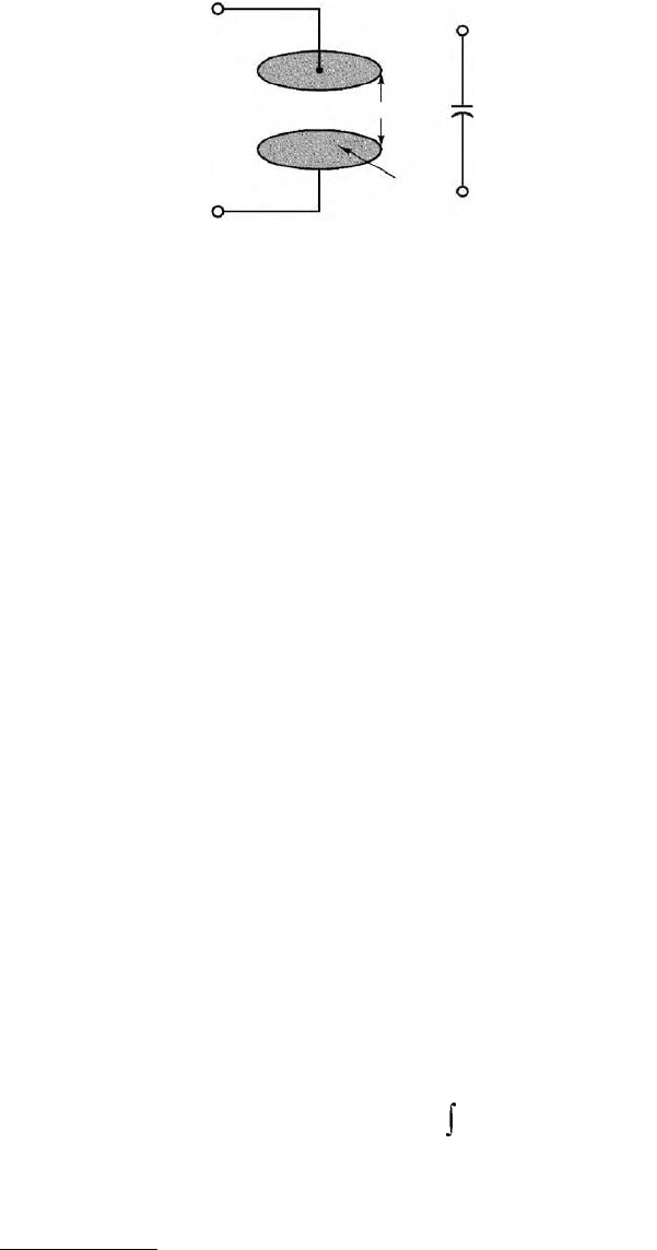
11.4.1.1 The Ideal Capacitor
A physical capacitor is a device that can store energy in the form of a charge separation when appropriately
polarized by an electric field (i.e., a voltage). The simplest capacitor configuration consists of two parallel
FIGURE 11.34 Representation of nonlinear element in
a linear circuit.
v
T
v
x
i
x
Nonlinear element as a load. We wish
to solve for v
x
and i
x
.
Nonlinear
element
+
+
–
–
R
T
v
T
R
T
i
x
v
x
+=
i
x
I
0
e
αν
x
, v 0>=
v
T
R
T
i
x
v
x
+=
9258_C011.fm Page 21 Tuesday, October 2, 2007 4:18 AM
11-22 Mechatronic Systems, Sensors, and Actuators
conducting plates of cross-sectional area A, separated by air (or another dielectric* material, such as
mica or Teflon). Figure 11.35 depicts a typical configuration and the circuit symbol for a capacitor.
The presence of an insulating material between the conducting plates does not allow for the flow of
DC current; thus, a capacitor acts as an open circuit in the presence of DC currents. However, if the voltage
present at the capacitor terminals changes as a function of time, so will the charge that has accumulated
at the two capacitor plates, since the degree of polarization is a function of the applied electric field,
which is time-varying. In a capacitor, the charge separation caused by the polarization of the dielectric
is proportional to the external voltage, that is, to the applied electric field:
(11.30)
where the parameter C is called the capacitance of the element and is a measure of the ability of the
device to accumulate, or store, charge. The unit of capacitance is the coulomb/volt and is called the farad
(F). The farad is an unpractically large unit; therefore, it is common to use microfarads (1 µF = 10
−6
F)
or picofarads (1 pF = 10
–12
F). From Equation 11.30 it becomes apparent that if the external voltage
applied to the capacitor plates changes in time, so will the charge that is internally stored by the capacitor:
(11.31)
Thus, although no current can flow through a capacitor if the voltage across it is constant, a time-varying
voltage will cause charge to vary in time. The change with time in the stored charge is analogous to a
current. The relationship between the current and voltage in a capacitor is as follows:
(11.32)
If the above differential equation is integrated, one can obtain the following relationship for the voltage
across a capacitor:
(11.33)
Equation 11.33 indicates that the capacitor voltage depends on the past current through the capacitor,
up until the present time, t. Of course, one does not usually have precise information regarding the flow
FIGURE 11.35 Structure of parallel-plate capacitor.
*A dielectric material contains a large number of electric dipoles, which become polarized in the presence of an
electric field.
d
A
C
Parallel-plate capacitor with air
gap d (air is the dielectric)
Circuit
symbol
+
+
–
–
C =
___
εA
d
ε = permittivity of air
= 8.854 × 10
−12
F/m
QCV=
qt() Cv t()=
it() C
dv t()
dt
------------
=
v
C
t()
1
C
---
i
C
dt
∞–
t
0
=
9258_C011.fm Page 22 Tuesday, October 2, 2007 4:18 AM
Electrical Engineering 11-23
of capacitor current for all past time, and so it is useful to define the initial voltage (or initial condition)
for the capacitor according to the following, where t
0
is an arbitrary initial time:
(11.34)
The capacitor voltage is now given by the expression
(11.35)
The significance of the initial voltage, V
0
, is simply that at time t
0
some charge is stored in the capacitor,
giving rise to a voltage, v
C
(t
0
), according to the relationship Q = CV. Knowledge of this initial condition
is sufficient to account for the entire past history of the capacitor current (see Figure 11.36).
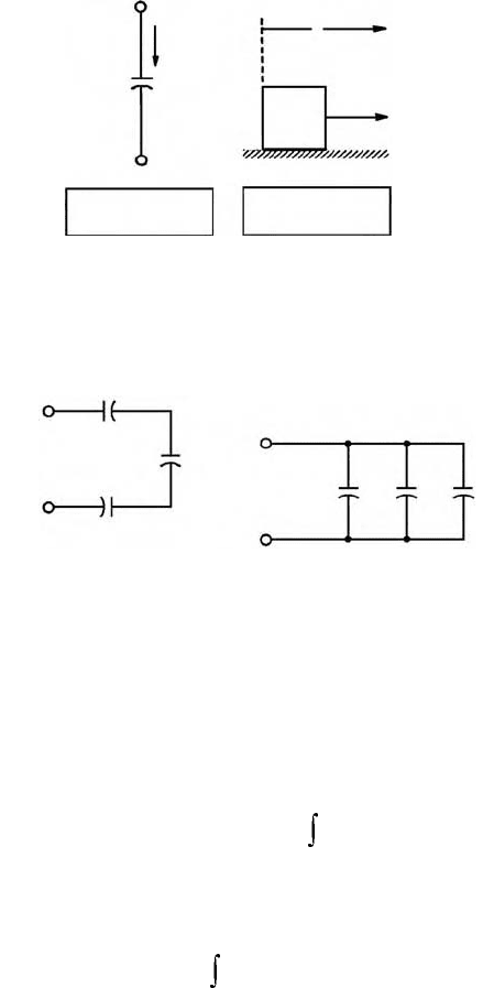
From the standpoint of circuit analysis, it is important to point out that capacitors connected in series
and parallel can be combined to yield a single equivalent capacitance. The rule of thumb, which is
illustrated in Figure 11.37, is the following: capacitors in parallel add; capacitors in series combine
according to the same rules used for resistors connected in parallel.
Physical capacitors are rarely constructed of two parallel plates separated by air, because this config-
uration yields very low values of capacitance, unless one is willing to tolerate very large plate areas. In
order to increase the capacitance (i.e., the ability to store energy), physical capacitors are often made of
tightly rolled sheets of metal film, with a dielectric (paper or Mylar) sandwiched in-between. Table 11.3
illustrates typical values, materials, maximum voltage ratings, and useful frequency ranges for various
FIGURE 11.36 Defining equation for the ideal capacitor, and analogy with force–mass system.
FIGURE 11.37 Combining capacitors in a circuit.
v
C
(t)
i
C
(t)
+
–
u =
__
_
dx
dt
f = M
___
du
dt
i
C
(t) = C
______
dv
C
(t)
dt
C
x
M
f
Capacitances in series combine
like resistors in parallel
Capacitances in parallel add
C
1
C
1
C
2
C
2
C
3
C
3
C
EQ
=
___________
1
C
1
1
C
2
__
+
__
+
__
1
C
3
1
C
EQ
= C
1
+ C
2
+ C
3
V
0
v
C
= tt
0
=()
1
C
---
i
C
dt
∞–
t
=
v
C
t()
1
C
---
i
C
tdV
0
t ≥ t
0
+
t
0
t
=
9258_C011.fm Page 23 Tuesday, October 2, 2007 4:18 AM

11-24 Mechatronic Systems, Sensors, and Actuators
types of capacitors. The voltage rating is particularly important, because any insulator will break down
if a sufficiently high voltage is applied across it. The energy stored in a capacitor is given by
Example 11.3 Capacitive Displacement Transducer and Microphone
As shown in Figure 11.26, the capacitance of a parallel-plate capacitor is given by the expression
where
ε
is the permittivity of the dielectric material, A the area of each of the plates, and d their separa-
tion. The permittivity of air is
ε
0
= 8.854 × 10
–12
F/m, so that two parallel plates of area 1 m
2
, separated
by a distance of 1 mm, would give rise to a capacitance of 8.854 × 10
–3
µ
F, a very small value for a very
large plate area. This relative inefficiency makes parallel-plate capacitors impractical for use in electronic
circuits. On the other hand, parallel-plate capacitors find application as motion transducers, that is, as
devices that can measure the motion or displacement of an object. In a capacitive motion transducer,
the air gap between the plates is designed to be variable, typically by fixing one plate and connecting the
other to an object in motion. Using the capacitance value just derived for a parallel-plate capacitor, one
can obtain the expression
where C is the capacitance in picofarad, A is the area of the plates in square millimeter, and x is the
(variable) distance in milimeter. It is important to observe that the change in capacitance caused by the
displacement of one of the plates is nonlinear, since the capacitance varies as the inverse of the displace-
ment. For small displacements, however, the capacitance varies approximately in a linear fashion.
The sensitivity, S, of this motion transducer is defined as the slope of the change in capacitance per
change in displacement, x, according to the relation
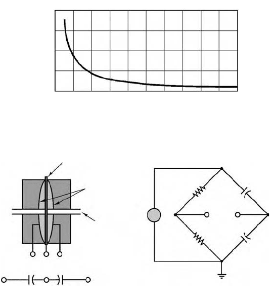
Thus, the sensitivity increases for small displacements. This behavior can be verified by plotting the
capacitance as a function of x and noting that as x approaches zero, the slope of the nonlinear C(x) curve
becomes steeper (thus the greater sensitivity). Figure 11.38 depicts this behavior for a transducer with
area equal to 10 mm
2
.
TABLE 11.3 Capacitors
Material Capacitance Range Maximum Voltage (V) Frequency Range (Hz)
Mica 1 pF–0.1 µF 100–600 10
3
–10
10
Ceramic 10 pF–1 µF 50–1000 10
3
–10
10
Mylar 0.001–10 µF 50–500 10
2
–10
8
Paper 1000 pF–50 µF 100–105 10
2
–10
8
Electrolytic 0.1 µF–0.2 F 3–600 10–10
4
W
C
t()
1
2
--
Cv
C
2
t() J()=
C
ε
A
d
------
=
C
8.854 10
3–
A×
x
----------------------------------
=
S
dC
dx
-------
8.854 10
3–
A×
2x
2
----------------------------------
– pF/mm()==
9258_C011.fm Page 24 Tuesday, October 2, 2007 4:18 AM
Electrical Engineering 11-25
This simple capacitive displacement transducer actually finds use in the popular capacitive (or con-
denser) microphone, in which the sound pressure waves act to displace one of the capacitor plates. The
change in capacitance can then be converted into a change in voltage or current by means of a suitable
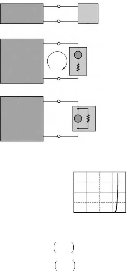
circuit. An extension of this concept that permits measurement of differential pressures is shown in
simplified form in Figure 11.39. In the figure, a three-terminal variable capacitor is shown to be made
up of two fixed surfaces (typically, spherical depressions ground into glass disks and coated with a
conducting material) and of a deflecting plate (typically made of steel) sandwiched between the glass
disks. Pressure inlet orifices are provided, so that the deflecting plate can come into contact with the
fluid whose pressure it is measuring. When the pressure on both sides of the deflecting plate is the same,
the capacitance between terminals b and d, C
bd
, will be equal to that between terminals b and c, C
bc
. If
any pressure differential exists, the two capacitances will change, with an increase on the side where the
deflecting plate has come closer to the fixed surface and a corresponding decrease on the other side.
This behavior is ideally suited for the application of a bridge circuit, similar to the Wheatstone bridge
circuit illustrated in Example 11.2, and also shown in Figure 11.39. In the bridge circuit, the output
voltage, v
out
, is precisely balanced when the differential pressure across the transducer is zero, but it will
deviate from zero whenever the two capacitances are not identical because of a pressure differential across
the transducer. We shall analyze the bridge circuit later in Example 11.4.
11.4.1.2 The Ideal Inductor
The ideal inductor is an element that has the ability to store energy in a magnetic field. Inductors are
typically made by winding a coil of wire around a core, which can be an insulator or a ferromagnetic
material, shown in Figure 11.40. When a current flows through the coil, a magnetic field is established,
as you may recall from early physics experiments with electromagnets. In an ideal inductor, the resistance
FIGURE 11.38 Response of a capacitive displacement transducer.
FIGURE 11.39 Capacitive pressure transducer and related bridge circuit.
10
50
100
150
200
23
x (mm)
Capacitance versus displacement
C (pF)
45 768910
Circuit model
Bridge configuration
Thin deflecting plate
Fixed surfaces
Pressure inlet
R
2
R
1
C
bc
C
db
V
out
~
–
–
+
+
v
s
(t)
c
c
b
b
d
d
c
b
a
d
9258_C011.fm Page 25 Tuesday, October 2, 2007 4:18 AM