Bichop R.H. (Ed.) Mechatronic Systems, Sensors, and Actuators: Fundamentals and Modeling
Подождите немного. Документ загружается.

11-6 Mechatronic Systems, Sensors, and Actuators
cable—or it may be exploited in an electrical circuit in a useful way. Nevertheless, practically all circuit
elements exhibit some resistance; as a consequence, current flowing through an element will cause energy
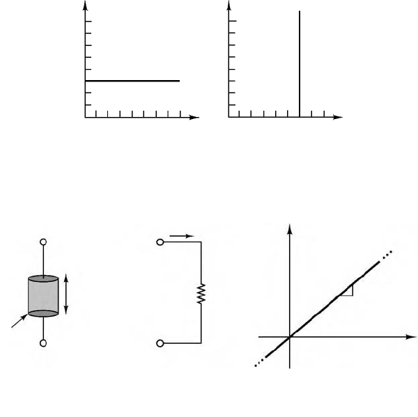
to be dissipated in the form of heat. An ideal resistor is a device that exhibits linear resistance properties
according to Ohm’s law, which states that
(11.10)
that is, that the voltage across an element is directly proportional to the current flow through it. R is the
value of the resistance in units of ohms (Ω), where
(11.11)
The resistance of a material depends on a property called resistivity, denoted by the symbol
ρ
; the
inverse of resistivity is called conductivity and is denoted by the symbol
σ
. For a cylindrical resistance
element (shown in Figure 11.8), the resistance is proportional to the length of the sample, l, and inversely
proportional to its cross-sectional area, A, and conductivity,
σ
.
(11.12)
It is often convenient to define the conductance of a circuit element as the inverse of its resistance.
The symbol used to denote the conductance of an element is G, where
(11.13)
FIGURE 11.7 i–v characteristics of ideal sources.
FIGURE 11.8 The resistance element.
i
v
8
7
6
5
4
3
2
1
012345 678
i–v characteristic
of a 3 A current source
i–v characteristic
of a 6 A voltage source
i
v
8
7
6
5
4
3
2
1
01 23 4 5 6 78
ii
v
R =
Physical resistors
with resistance R.
Typical materials are
carbon, metal film.
Circuit symbol i–v characteristic
R
A
σ
l
l
v
1/R
–
+
A
VIR=
1 Ω 1 V/A=
v
1
σ
A
-------
i=
G
1
R
---
siemens (S), where 1 S 1 A/V==
9258_C011.fm Page 6 Tuesday, October 2, 2007 4:18 AM
Electrical Engineering 11-7
Thus, Ohm’s law can be rested in terms of conductance, as
(11.14)
Ohm’s law is an empirical relationship that finds widespread application in electrical engineering
because of its simplicity. It is, however, only an approximation of the physics of electrically conducting
materials. Typically, the linear relationship between voltage and current in electrical conductors does not
apply at very high voltages and currents. Further, not all electrically conducting materials exhibit linear
behavior even for small voltages and currents. It is usually true, however, that for some range of voltages
and currents, most elements display a linear i–v characteristic.
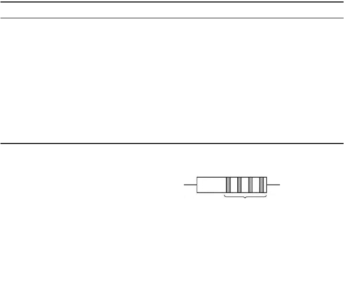
The typical construction and the circuit symbol of the resistor are shown in Figure 11.8. Resistors made
of cylindrical sections of carbon (with resistivity
ρ
= 3.5
×
10
–5
Ω
m) are very common and are commer-
cially available in a wide range of values for several power ratings (as will be explained shortly). Another
commonly employed construction technique for resistors employs metal film. A common power rating
for resistors used in electronic circuits (e.g., in most consumer electronic appliances such as radios and
television sets) is W. Table 11.1 lists the standard values for commonly used resistors and the color code
associated with these values (i.e., the common combinations of the digits
b
1
b
2
b
3
as defined in Figure 11.9.
For example, if the first three color bands on a resistor show the colors red (
b
1
=
2), violet (
b
2
= 7), and
yellow (
b
3
= 4), the resistance value can be interpreted as follows:
In Table 11.1, the leftmost column represents the complete color code; columns to the right of it only
show the third color, since this is the only one that changes. For example, a 10-Ω resistor has the code
brown-black-black, while a 100-Ω resistor has brown-black-brown.
TABLE 11.1 Common Resistor Values (
1
/
8
-,
1
/
4
-,
1
/
2
-, 1-, 2-W Rating)
Ω Code Ω Multiplier kΩ Multiplier kΩ Multiplier kΩ Multiplier
10 Brn-blk-blk 100 Brown 1.0 Red 10 Orange 100 Yellow
12 Brn-red-blk 120 Brown 1.2 Red 12 Orange 120 Yellow
15 Brn-grn-blk 150 Brown 1.5 Red 15 Orange 150 Yellow
18 Brn-gry-blk 180 Brown 1.8 Red 18 Orange 180 Yellow
22 Red-red-blk 220 Brown 2.2 Red 22 Orange 220 Yellow
27 Red-vlt-blk 270 Brown 2.7 Red 27 Orange 270 Yellow
33 Org-org-blk 330 Brown 3.3 Red 33 Orange 330 Yellow
39 Org-wht-blk 390 Brown 3.9 Red 39 Orange 390 Yellow
47 Ylw-vlt-blk 470 Brown 4.7 Red 47 Orange 470 Yellow
56 Grn-blu-blk 560 Brown 5.6 Red 56 Orange 560 Yellow
68 Blu-gry-blk 680 Brown 6.8 Red 68 Orange 680 Yellow
82 Gry-red-blk 820 Brown 8.2 Red 82 Orange 820 Yellow
FIGURE 11.9 Resistor color code.
b
4
b
3
b
2
b
1
Black 0
1
2
3
4
5
Brown
Red
Orange
Yellow
Green
Resistor value = (b
1
b
2
) × 10
b
3
;
b
4
= % tolerance in actual value
Blue 6
7
8
9
10%
5%
Violet
Gray
White
Silver
Gold
Color bands
IGV=
1
4
--
R 27 10
4
× 270,000 Ω 270 kΩ== =
9258_C011.fm Page 7 Tuesday, October 2, 2007 4:18 AM
11-8 Mechatronic Systems, Sensors, and Actuators
In addition to the resistance in ohms, the maximum allowable power dissipation (or power rating) is
typically specified for commercial resistors. Exceeding this power rating leads to overheating and can
cause the resistor to literally start on fire. For a resistor R, the power dissipated is given by
(11.15)
That is, the power dissipated by a resistor is proportional to the square of the current flowing through
it, as well as the square of the voltage across it. The following example illustrates a common engineering
application of resistive elements: the resistance strain gauge.
Example 11.1 Resistance Strain Gauges
A common application of the resistance concept to engineering measurements is the resistance strain
gauge. Strain gauges are devices that are bonded to the surface of an object, and whose resistance varies
as a function of the surface strain experienced by the object. Strain gauges may be used to perform
measurements of strain, stress, force, torque, and pressure. Recall that the resistance of a cylindrical
conductor of cross-sectional area A, length L, and conductivity
σ
is given by the expression
If the conductor is compressed or elongated as a consequence of an external force, its dimensions will
change, and with them its resistance. In particular, if the conductor is stretched, its cross-sectional area
will decrease and the resistance will increase. If the conductor is compressed, its resistance decreases,
since the length, L, will decrease. The relationship between change in resistance and change in length is
given by the gauge factor, G, defined by
and since the strain
ε
is defined as the fractional change in length of an object by the formula
the change in resistance due to an applied strain
ε
is given by the expression
where R
0
is the resistance of the strain gauge under no strain and is called the zero strain resistance. The
value of G for resistance strain gauges made of metal foil is usually about 2.
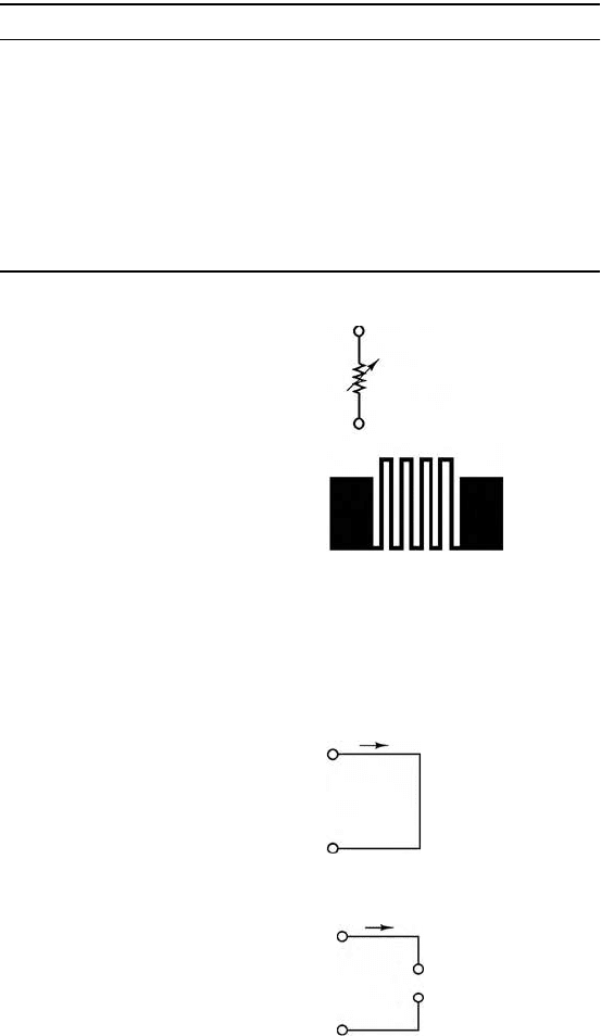
Figure 11.10 depicts a typical foil strain gauge. The maximum strain that can be measured by a foil
gauge is about 0.4–0.5%; that is, ∆L/L = 0.004 to 0.005. For a 120-Ω gauge, this corresponds to a change
in resistance of the order of 0.96–1.2 Ω. Although this change in resistance is very small, it can be detected
by means of suitable circuitry. Resistance strain gauges are usually connected in a circuit called the
Wheatstone bridge, which we analyze later in this section.
11.2.3.1 Open and Short Circuits
Two convenient idealizations of the resistance element are provided by the limiting cases of Ohm’s law
as the resistance of a circuit element approaches zero or infinity. A circuit element with resistance
approaching zero is called a short circuit. Intuitively, one would expect a short circuit to allow for
unimpeded flow of current. In fact, metallic conductors (e.g., short wires of large diameter) approximate
the behavior of a short circuit. Formally, a short circuit is defined as a circuit element across which the
voltage is zero, regardless of the current flowing through it. Figure 11.11 depicts the circuit symbol for
an ideal short circuit.
PVII
2
R
V
2
R
-----
== =
R
L
σ
A
-------
=
G
∆R/R
∆L/L
-------------
=
ε
∆L
L
-------
=
∆RR
0
G
ε
=
9258_C011.fm Page 8 Tuesday, October 2, 2007 4:18 AM
Electrical Engineering 11-9
Physically, any wire or other metallic conductor will exhibit some resistance, though small. For practical
purposes, however, many elements approximate a short circuit quite accurately under certain conditions.
For example, a large-diameter copper pipe is effectively a short circuit in the context of a residential
electrical power supply, while in a low-power microelectronic circuit (e.g., an FM radio) a short length of
24 gauge wire (refer to Table 11.2 for the resistance of 24 gauge wire) is a more than adequate short circuit.
A circuit element whose resistance approaches infinity is called an open circuit. Intuitively, one would
expect no current to flow through an open circuit, since it offers infinite resistance to any current. In an
open circuit, we would expect to see zero current regardless of the externally applied voltage. Figure 11.12
illustrates this idea.
TABLE 11.2 Resistance of Copper Wire
AWG Size Number of Strands Diameter per Strand Resistance per 1000 ft (Ω)
24 Solid 0.0201 28.4
24 7 0.0080 28.4
22 Solid 0.0254 18.0
22 7 0.0100 19.0
20 Solid 0.0320 11.3
20 7 0.0126 11.9
18 Solid 0.0403 7.2
18 7 0.0159 7.5
16 Solid 0.0508 4.5
16 19 0.0113 4.7
FIGURE 11.10 The resistance strain gauge.
FIGURE 11.11 The short circuit.
FIGURE 11.12 The open circuit.
Circuit symbol for
the strain gauge
Metal-foil resistance strain gauge.
The foil is formed by a photo-
etching process and is less than
0.00002 in. thick. Typical resistance
values are 120, 350, and 1000 Ω.
The wide areas are bonding pads
for electrical connections.
R
G
i
v
+
The short circuit:
R = 0
v = 0 for any i
–
i
v
–
+
The open circuit:
R →∞
i = 0 for any v
9258_C011.fm Page 9 Tuesday, October 2, 2007 4:18 AM
11-10 Mechatronic Systems, Sensors, and Actuators
In practice, it is not too difficult to approximate an open circuit; any break in continuity in a conducting
path amounts to an open circuit. The idealization of the open circuit, as defined in Figure 11.12, does
not hold, however, for very high voltages. The insulating material between two insulated terminals will
break down at a sufficiently high voltage. If the insulator is air, ionized particles in the neighborhood of
the two conducting elements may lead to the phenomenon of arcing; in other words, a pulse of current
may be generated that momentarily jumps a gap between conductors (thanks to this principle, we are
able to ignite the air–fuel mixture in a spark-ignition internal combustion engine by means of spark
plugs). The ideal open and short circuits are useful concepts and find extensive use in circuit analysis.
11.2.3.2 Series Resistors and the Voltage Divider Rule
Although electrical circuits can take rather complicated forms, even the most involved circuits can be reduced
to combinations of circuit elements in parallel and in series. Thus, it is important that you become acquainted
with parallel and series circuits as early as possible, even before formally approaching the topic of network
analysis. Parallel and series circuits have a direct relationship with Kirchhoff ’s laws. The objective of this
section and the next is to illustrate two common circuits based on series and parallel combinations of
resistors: the voltage and current dividers. These circuits form the basis of all network analysis; it is therefore
important to master these topics as early as possible.
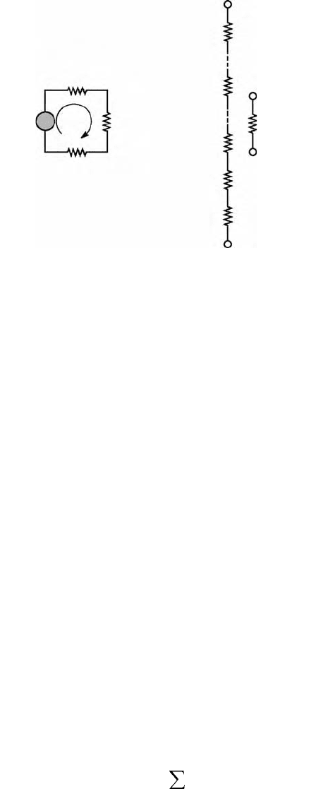
For an example of a series circuit, refer to the circuit of Figure 11.13, where a battery has been connected
to resistors R
1
, R
2
, and R
3
. The following definition applies.
Definition
Two or more circuit elements are said to be in series if the same current flows through each of the elements.
The three resistors could thus be replaced by a single resistor of value R
EQ
without changing the amount
of current required of the battery. From this result we may extrapolate to the more general relationship
defining the equivalent resistance of N series resistors:
(11.16)
which is also illustrated in Figure 11.13. A concept very closely tied to series resistors is that of the voltage
divider.
FIGURE 11.13 Voltage divider rule.
R
N
R
EQ
R
n
R
3
R
2
R
1
i
v
1
v
3
R
2
v
2
R
1
+
–
1. 5 V
The current i flows through each of
the four series elements. Thus, by
KVL,
1.5 = v
1
+
v
2
+
v
3
N Series resistors are equivalent to a
single resistor equal to the sum of
the individual resistances.
+
+
+
–
–
–
R
EQ
R
n
n=1
N
=
9258_C011.fm Page 10 Tuesday, October 2, 2007 4:18 AM
Electrical Engineering 11-11
The general form of the voltage divider rule for a circuit with N series resistors and a voltage source is
(11.17)
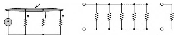
11.2.3.3 Parallel Resistors and the Current Divider Rule
A concept analogous to that of the voltage may be developed by applying Kirchhoff’s current law to a
circuit containing only parallel resistances.
Definition
Two or more circuit elements are said to be in parallel if the same voltage appears across each of the
elements (see Figure 11.14).
N resistors in parallel act as a single equivalent resistance, R
EQ
, given by the expression
(11.18)
or
(11.19)
Very often in the remainder of this book we shall refer to the parallel combination of two or more
resistors with the following notation:
where the symbol signifies “in parallel with.”
The general expression for the current divider for a circuit with N parallel resistors is the following:
(11.20)
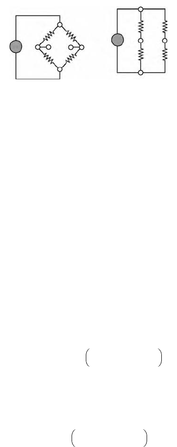
Example 11.2 The Wheatstone Bridge
The Wheatstone bridge is a resistive circuit that is frequently encountered in a variety of measurement circuits.
The general form of the bridge is shown in Figure 11.15a, where R
1
, R
2
, and R
3
are known, while R
x
is an
unknown resistance, to be determined. The circuit may also be redrawn as shown in Figure 11.15b. The
latter circuit will be used to demonstrate the use of the voltage divider rule in a mixed series-parallel circuit.
FIGURE 11.14 Parallel circuits.
The voltage v appears across each parallel
element; by KCL, i
S
= i
1
+ i
2
+ i
3
i
S
R
1
R
2
R
1
R
2
R
EQ
R
3
R
n
R
N
R
3
v
i
1
i
2
i
3
KCL applied at this node
+
–
N resistors in parallel are equivalent to a single equivalent
resistor with resistance equal to the inverse of the sum of
the inverse resistances.
v
n
R
n
R
1
R
2
…
R
n
…
R
N
+++++
-------------------------------------------------------------------
v
S
=
1
R
EQ
--------
1
R
1
-----
1
R
2
-----
…
1
R
N
------
+++=
R
EQ
1
1/R
1
1/R
2
…
1/R
N
+++
-----------------------------------------------------------
=
R
1
R
2
…
|| ||
||
i
n
1/R
n
1/R
1
1/R
2
…
1/R
n
…
1/R
N
+++++
-----------------------------------------------------------------------------------------
i
S
Current divider=
9258_C011.fm Page 11 Tuesday, October 2, 2007 4:18 AM
11-12 Mechatronic Systems, Sensors, and Actuators
The objective is to determine the unknown resistance R
x
.
1. Find the value of the voltage v
ad
= v
ad
– v
bd
in terms of the four resistances and the source voltage,
v
S
. Note that since the reference point d is the same for both voltages, we can also write v
ab
= v
a
– v
b
.
2. If R
1
= R
2
= R
3
= 1 kΩ, v
S
= 12 V, and v
ab
= 12 mV, what is the value of R
x
?
Solution
1. First, we observe that the circuit consists of the parallel combination of three subcircuits: the
voltage source, the series combination of R
1
and R
2
, and the series combination of R
3
and R
x
. Since
these three subcircuits are in parallel, the same voltage will appear across each of them, namely,
the source voltage, v
S
.
Thus, the source voltage divides between each resistor pair, R
1
–R
2
and R
3
–R
x
, according to the
voltage divider rule: v
a
is the fraction of the source voltage appearing across R
2
, while v
b
is the
voltage appearing across R
x
:
Finally, the voltage difference between points a and b is given by
This result is very useful and quite general, and it finds application in numerous practical circuits.
2. In order to solve for the unknown resistance, we substitute the numerical values in the preceding
equation to obtain
which may be solved for R
x
to yield
11.2.4 Practical Voltage and Current Sources
Idealized models of voltage and current sources fail to take into consideration the finite-energy nature
of practical voltage and current sources. The objective of this section is to extend the ideal models to
models that are capable of describing the physical limitations of the voltage and current sources used in
practice. Consider, for example, the model of an ideal voltage source. As the load resistance (R) decreases,
the source is required to provide increasing amounts of current to maintain the voltage v
S
(t) across
FIGURE 11.15 Wheatstone bridge circuits.
R
x
v
a
v
b
v
S
v
S
v
a
v
b
b
d
c
a
b
d
a
c
R
3
R
1
R
3
(a) (b)
R
x
R
2
R
1
R
2
–
+
–
+
v
a
v
S
R
2
R
1
R
2
+
-----------------
and v
b
v
S
R
x
R
3
R
x
+
-----------------
==
v
ab
v
a
v
b
– v
S
R
2
R
1
R
2
+
-----------------
R
x
R
3
R
x
+
------------------–
==
0.012 12
1000
2000
-----------
R
x
1000 R
x
+
------------------------–
=
R
x
996 Ω=
9258_C011.fm Page 12 Tuesday, October 2, 2007 4:18 AM
Electrical Engineering 11-13
its terminal:
(11.21)
This circuit suggests that the ideal voltage source is required to provide an infinite amount of current to
the load, in the limit as the load resistance approaches zero.
Figure 11.16 depicts a model for a practical voltage source; this is composed of an ideal voltage source,
v
S
, in series with a resistance, r
S
. The resistance r
S
in effect poses a limit to the maximum current the
voltage source can provide:
(11.22)
It should be apparent that a desirable feature of an ideal voltage source is a very small internal resistance,
so that the current requirements of an arbitrary load may be satisfied.
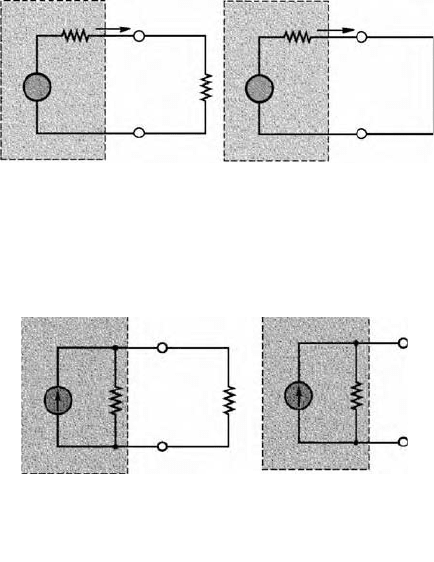
A similar modification of the ideal current source model is useful to describe the behavior of a practical
current source. The circuit illustrated in Figure 11.17 depicts a simple representation of a practical current
source, consisting of an ideal source in parallel with a resistor. Note that as the load resistance approaches
infinity (i.e., an open circuit), the output voltage of the current source approaches its limit,
(11.23)
A good current source should be able to approximate the behavior of an ideal current source. Therefore,
a desirable characteristic for the internal resistance of a current source is that it be as large as possible.
FIGURE 11.16 Practical voltage source.
FIGURE 11.17 Practical current source.
it()
v
S
t()
R
-----------
=
i
S max
v
S
r
S
----
=
v
S max
i
S
r
S
=
Practical voltage
source
The maximum (short circuit)
current which can be supplied
by a practical voltage source is
i
S
=
______
v
S
r
S
+ R
L
i
S max
=
__
v
S
r
S
i
S max
r
S
r
S
i
S
v
S
v
L
R
L
v
S
v
L
R
L
lim
→0 i
S
=
___
v
S
r
S
–
+
–
–
+
+
–
+
A model for practical current
sources consists of an ideal
source in parallel with an
internal resistance.
Maximum output
voltage for practical
current source with
open-circuit load:
v
S max
= i
S
r
S
i
S
i
S
r
S
v
S
r
S
v
S
R
L
–
+
–
+
9258_C011.fm Page 13 Tuesday, October 2, 2007 4:18 AM
11-14 Mechatronic Systems, Sensors, and Actuators
11.2.5 Measuring Devices
11.2.5.1 The Ammeter
The ammeter is a device that, when connected in series with a circuit element, can measure the current
flowing through the element. Figure 11.18 illustrates this idea. From Figure 11.18, two requirements are
evident for obtaining a correct measurement of current:
1. The ammeter must be placed in series with the element whose current is to be measured (e.g.,
resistor R
2
).
2. The ammeter should not resist the flow of current (i.e., cause a voltage drop), or else it will not
be measuring the true current flowing the circuit. An ideal ammeter has zero internal resistance.
11.2.5.2 The Voltmeter
The voltmeter is a device that can measure the voltage across a circuit element. Since voltage is the
difference in potential between two points in a circuit, the voltmeter needs to be connected across the
element whose voltage we wish to measure. A voltmeter must also fulfill two requirements:
1. The voltmeter must be placed in parallel with the element whose voltage it is measuring.
2. The voltmeter should draw no current away from the element whose voltage it is measuring, or
else it will not be measuring the true voltage across that element. Thus, an ideal voltmeter has
infinite internal resistance.
Figure 11.19 illustrates these two points.
Once again, the definitions just stated for the ideal voltmeter and ammeter need to be augmented by
considering the practical limitations of the devices. A practical ammeter will contribute some series
resistance to the circuit in which it is measuring current; a practical voltmeter will not act as an ideal
open circuit but will always draw some current from the measured circuit. Figure 11.20 depicts the circuit
models for the practical ammeter and voltmeter.
FIGURE 11.18 Measurement of current.
FIGURE 11.19 Measurement of voltage.
Symbol for
ideal ammeter
–
+
–
+
A series
circuit
Circuit for the measurement
of the current i
R
2
R
2
R
1
R
1
A
ii
v
S
v
S
A
–
+
–
+
–
+
–
+
–
+
A series
circuit
Ideal
voltmeter
R
1
R
1
Circuit for the measurement
of the voltage v
2
v
2
v
2
R
2
R
2
v
2
VV
ii
v
S
v
S
9258_C011.fm Page 14 Tuesday, October 2, 2007 4:18 AM
Electrical Engineering 11-15
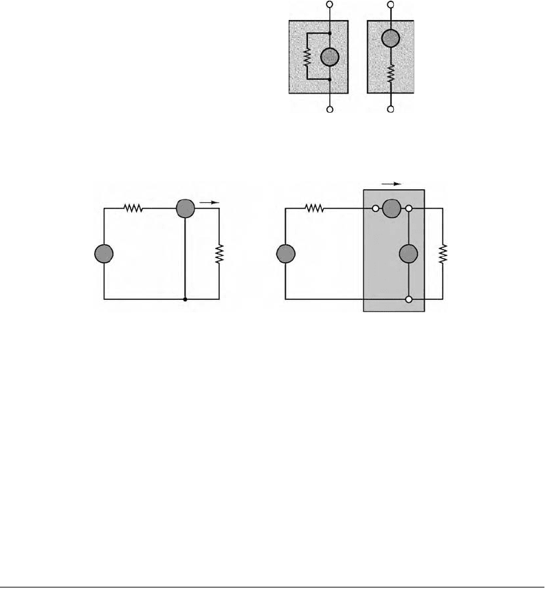
All of the considerations that pertain to practical ammeters and voltmeters can be applied to the
operation of a wattmeter, a measuring instrument that provides a measurement of the power dissipated
by a circuit element, since the wattmeter is in effect made up of a combination of a voltmeter and an
ammeter.
Figure 11.21 depicts the typical connection of a wattmeter in the same series circuit used in the
preceding paragraphs. In effect, the wattmeter measures the current flowing through the load and,
simultaneously, the voltage across it multiplies the two to provide a reading of the power dissipated by
the load.
11.3 Resistive Network Analysis
This section will illustrate the fundamental techniques for the analysis of resistive circuits. The methods
introduced are based on Kirchhoff’s and Ohm’s laws. The main thrust of the section is to introduce and
illustrate various methods of circuit analysis that will be applied throughout the book.
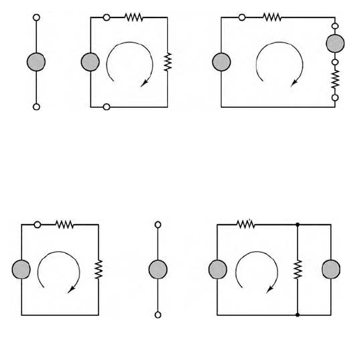
11.3.1 The Node Voltage Method
Node voltage analysis is the most general method for the analysis of electrical circuits. In this section, its
application to linear resistive circuits will be illustrated. The node voltage method is based on defining
the voltage at each node as an independent variable. One of the nodes is selected as a reference node
(usually—but not necessarily—ground), and each of the other node voltages is referenced to this node.
Once each node voltage is defined, Ohm’s law may be applied between any two adjacent nodes in order
to determine the current flowing in each branch. In the node voltage method, each branch current is
expressed in terms of one or more node voltages; thus, currents do not explicitly enter into the equations.
Figure 11.22 illustrates how one defines branch currents in this method.
FIGURE 11.20 Models for practical ammeter and
voltmeter.
FIGURE 11.21 Measurement of power.
Practical
voltmeter
Practical
ammeter
A
V
r
m
r
m
–
+
–
+
Measurement of the power
dissipated in the resistor R
2
:
P
2
= v
2
i
Internal wattmeter connections
R
2
R
2
R
1
WA
V
R
1
i
i
v
S
v
S
–
+
v
2
–
+
v
2
9258_C011.fm Page 15 Tuesday, October 2, 2007 4:18 AM