Bhushan B. Nanotribology and Nanomechanics: An Introduction
Подождите немного. Документ загружается.

202 Markus Morgenstern et al.
b
a
TCNQ TTF
b)
log I
Distance (nm)
012345678
AB
d)a)
ab
TCNQ TTF
e) f) g)
h)
c)
A
B
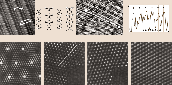
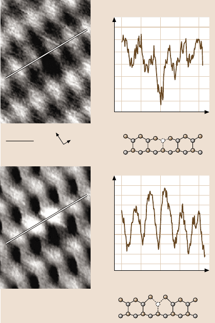
Fig. 5.15. (a) STM image of the ab-plane of the organic quasi-1-D conductor TTF-TCNQ,
T = 300 K; while the TCNQ chains are conducting, the TTF chains are insulating. (b) Stick-
and-ball model of the ab-plane of TTF-TCNQ. (c) STM image taken at T = 61 K, the ad-
ditional modulation due to the Peierls transition is visible in the profile along line A shown
in (d); the brown triangles mark the atomic periodicity and the black triangles the expected
CDW periodicity ((a)–(d) courtesy of Kageshima, Kanagawa). (e)–(h) Low-voltage STM
images of the two-dimensional CDW-system 1T-TaS
2
at T = 242 K (e), 298 K (f), 349 K (g),
357 K (h). A long-range, hexagonal modulation is visible besides the atomic spots; its perio-
dicity is highlighted by large white dots in (e); the additional modulation obviously weakens
with increasing T, but is still apparent in (f)and(g), as evidenced in the lower magnification
images in the insets ((e)–(h) courtesy of Lieber, Cambridge)
curs [82]. The corresponding phonon energy goes to zero, the atoms are slightly
displaced with the periodicity of the corresponding wave vector, and a charge den-
sity wave (CDW) with the same periodicity appears. Essentially, the CDW increases
the overlap of the electronic states with the phonon by phase-fixing with respect to
the atomic lattice. The Peierls transition naturally occurs in one-dimensional (1-D)
systems, where only two Fermi points are present, and, hence, preferential orienta-
tion is pathological. It can also occur in 2-D systems if large areas of the Fermi line
runinparallel.
STS studies of CDWs are numerous (e.g., [83,84]). Examples of a 1-D CDW
on a quasi-1-D bulk material and of a 2-D CDW are shown in Fig. 5.15a–d and
Fig. 5.15e, respectively [85,86]. In contrast to usual scattering states, where LDOS
corrugationsare onlyfound close to thescatterer,the corrugationsof CDWs are con-
tinuous across the surface. Heating the substrate toward the transition temperature
leads to a melting of the CDW lattice, as shown in Fig. 5.15f–h.
CDWs have also been found on monolayers of adsorbates such as a monolayer
of Pbon Ge(111)[87].These authorsperformeda nicetemperature-dependentstudy
revealingthatthe CDWis nucleatedby scatteringstates arounddefects,as one might
expect [88]. 1-D systems have also been prepared on surfaces showing Peierls tran-
5 Low-Temperature Scanning Probe Microscopy 203
sitions [89,90]. Finally, the energy gap occurring at the transition has been studied
by measuring dI/ dV(V)-curves [91].
Superconductors
An intriguing effect resulting from electron–phonon interaction is superconductiv-
ity. Here, the attractive part of the electron–phononinteraction leads to the coupling
of electronic states with opposite wave vector and mostly opposite spin [92]. Since
the resulting Cooper pairs are bosons, they can condense at LT, forming a coher-
ent many-particle phase, which can carry current without resistance. Interestingly,
defect scattering does not influence the condensate if the coupling along the Fermi
surface is homogeneous (s-wave superconductor). The reason is that the symmetry
of the scattering of the two components of a Cooper pair effectively leads to a scat-
tering from one Cooper pair state to another without affecting the condensate. This
is different if the scatterer is magnetic, since the different spin components of the
pair are scattered differently, leading to an effective pair breaking, which is visible
as a single-particle excitation within the superconducting gap. On a local scale, this
effect was first demonstrated by putting Mn, Gd, and Ag atoms on a Nb(110) sur-
face [93]. While the nonmagnetic Ag does not modify the gap shown in Fig. 5.16a,
it is modified in an asymmetric fashion close to Mn or Gd adsorbates, as shown in
Fig. 5.16b. The asymmetry of the additional intensity is caused by the breaking of
the particle–hole symmetry due to the exchange interaction between the localized
Mn state and the itinerate Nb states.
Another important local effect is caused by the relatively large coherence length
of the condensate. At a material interface, the condensate wave function cannot
stop abruptly, but overlaps into the surrounding material (proximity effect). Conse-
quently, a superconducting gap can be measured in areas of non-superconducting
material. Several studies have shown this effect on the local scale using metals and
doped semiconductors as surrounding materials [94,95].
While the classical type-I superconductors are ideal diamagnets, the so-called
type-II superconductors can contain magnetic flux. The flux forms vortices, each
containing one flux quantum. These vortices are accompanied by the disappearance
of the superconducting gap and, therefore, can be probed by STS [96]. LDOS maps
measured inside the gap lead to bright features in the area of the vortex core. Im-
portantly, the length scale of these features is different from the length scale of the
magnetic flux due to the difference between London’s penetration depth and the
coherence length. Thus, STS probes another property of the vortex than the usual
magnetic imaging techniques (see Sect. 5.5.4). Surprisingly, first measurements of
the vortices on NbSe
2
revealed vortices shaped as a sixfold star [97] (Fig. 5.16c).
With increasing voltage inside the gap, the orientation of the star rotates by 30
◦
(Fig. 5.16d,e). The shape of these stars could finally be reproduced by theory, as-
sumingan anisotropicpairingof electronsin the superconductor(Fig. 5.16f–h) [98].
Additionally, bound states inside the vortex core, which result from confinement
by the surrounding superconducting material, are found [97]. Further experiments
investigated the arrangement of the vortex lattice, including transitions between
204 Markus Morgenstern et al.
a) b)
c) d) e) f) g) h)
j) k)
dl/dV (10
–7
Ω
–1
)
(Volt)
–0.008 –0.004
1.2
0.8
0.4
0
0 0.004 0.008
dl/dV difference (10
–7
Ω
–1
)
Voltage (mV)
–4
0.4
0.2
0
–0.2
8–8 0 4
0–50 –50
3.0
2.6
2.2
1.8
1.4
1.0
0.6
0.2
Voltage (mV)
2 pA
0 pA
100 Å
i)
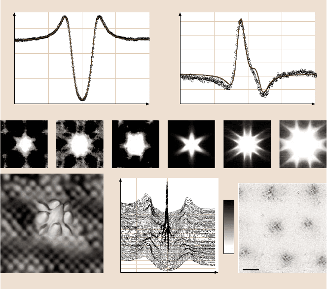
Fig. 5.16. (a)dI/ dV-curve of Nb(110) atT = 3.8K(symbols) in comparison with aBCS fit of
the superconducting gap of Nb (line). (b)Difference between the dI/ dV-curve taken directly
above a Mn-atom on Nb(110) and the dI/ dV-curve taken above the clean Nb(110) (symbols)
in comparison with a fit using the Bogulubov-de Gennes equations (line)((a),(b) courtesy
of Eigler, Almaden). (c)–(e)dI/ dV-images of a vortex core in the type-II superconduc-
tor 2H-NbSe
2
at 0 mV (c), 0.24 mV (d), and 0.48 mV (e)((c)–(e) courtesy of H.F. Hess).
(f)–(h) Corresponding calculated LDOS images within the Eilenberger framework ((f)–
(h) courtesy of Machida, Okayama). (i) Overlap of an STM image at V = −100 mV (back-
ground 2-D image) and a dI/dV-image at V = 0 mV (overlapped 3-D image) of optimally
doped Bi
2
Sr
2
CaCu
2
O
8+δ
containing 0.6% Zn impurities. The STM image shows the atomic
structure of the cleavage plane, while the dI/ dV-image shows a bound state within the su-
perconducting gap, which is located around a single Zn impurity. The fourfold symmetry
of the bound state reflects the d-like symmetry of the superconducting pairing function;
(j)dI/dV-curves taken at different positions across the Zn impurity; the bound state close
to 0 mV is visible close to the Zn atom; (k) LDOS in the vortex core of slightly over-
doped Bi
2
Sr
2
CaCu
2
O
8+δ
, B = 5T; the dI/ dV-image taken at B = 5 T is integrated over
V = 1−12 mV, and the corresponding dI/ dV-image at B = 0 T is subtracted to highlight the
LDOS induced by the magnetic field. The checkerboard pattern within the seven vortex cores
exhibits a periodicity, which is fourfold with respect to the atomic lattice shown in (i)andis
thus assumed to be a CDW ((i)–(k) courtesy of S. Davis, Cornell and S. Uchida, Tokyo)
5 Low-Temperature Scanning Probe Microscopy 205
hexagonal and quadratic lattices [99], the influence of pinning centers [100], and
the vortex motion induced by current [101].
The understandingof high-temperaturesuperconductivity(HTCS) is still an im-
portant topic. An almost accepted property of HTCS is its d-wave pairing sym-
metry. In contrast to s-wave superconductors, scattering can lead to pair breaking,
since the Cooper-pairdensity vanishesin certain directions. Indeed,scattering states
(bound states in the gap) around nonmagnetic Zn impurities have been observed in
Bi
2
Sr
2
CaCu
2
O
8+δ
(BSCCO) (Fig. 5.16i,j) [26]. They reveal a d-like symmetry, but
not the one expectedfrom simple Cooper-pairscattering. Other effects such as mag-
netic polarization in the environment probably have to be taken into account [102].
Moreover, it has been found that magnetic Ni impurities exhibit a weaker scatter-
ing structure than Zn impurities [103]. Thus, BSCCO shows exactly the opposite
behavior to that of Nb discussed above(Fig. 5.16a,b). An interesting topic is the im-
portance of inhomogeneities in HTCS materials. Evidence for inhomogeneities has
indeed been found in underdoped materials, where puddles of the superconducting
phase are shown to be embedded in non-superconductingareas [104].
Of course, vortices have also been investigated in HTCS materials [105]. Bound
states are found,but at energiesthat are in disagreement with simple models,assum-
ing a Bardeen–Cooper–Schrieffer (BCS)-like d-wave superconductor [106, 107].
Theory predicts, instead, that the bound states are magnetic-field-inducedspin den-
sity waves, stressing the competition between antiferromagnetic order and super-
conductivity in HTCS materials [108]. Since the spin density wave is accompanied
by a charge density wave of half wavelength, it can be probed by STS [109]. In-
deed, a checkerboard pattern of the right periodicity has been found in and around
vortex cores in BSCCO (Fig. 5.16k). It exceeds the width of an individual vortex
core, implying that the superconductingcoherence length is different from the anti-
ferromagnetic one.
Complex Systems (Manganites)
Complex phase diagrams are not restricted to HTCS materials (cuprates). They ex-
ist with similar complexity for other doped oxides such as manganites. Only a few
studies of these materials have been performed by STS, mainly showing the inho-
mogeneousevolutionof metallic and insulating phases[110,111].Similarities to the
granular case of an underdopedHTCS material are obvious. Since inhomogeneities
seem to be crucial in many of these materials, a local method such as STS might
continue to be important for the understanding of their complex properties.
5.4.6 Imaging Spin Polarization: Nanomagnetism
Conventional STS couples to the LDOS, i.e., the charge distribution of the elec-
tronic states. Since electrons also have spin, it is desirable to also probe the spin
distribution of the states. This can be achieved if the tunneling tip is covered by
a ferromagnetic material [112]. The coating acts as a spin filter or, more precisely,
the tunneling current depends on the relative angle α
ij
between the spins of the tip

206 Markus Morgenstern et al.
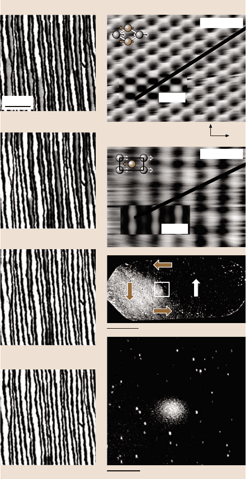
Fig. 5.17. (a)–(d) Spin-polarized STM images of 1.65 monolayer of Fe deposited on
a stepped W(110) surface measured at different B-fields, as indicated. Double-layer and
monolayer Fe stripes are formed on the W substrate; only the double-layer stripes exhibit
magnetic contrast with an out-of-plane sensitive tip, as used here. White and grey areas corre-
spond to different domains. Note that more white areas appear with increasing field. (e)STM
image of an antiferromagnetic Mn monolayer on W(110). (f) Spin-polarized STM-image of
the same surface (in-plane tip). The insets in (e)and(f) show the calculated STM and spin-
polarized STM images, respectively, and the stick-and-ball models symbolize the atomic and
the magnetic unit cell ((a)–(f) courtesy of M. Bode, Hamburg). (g) Spin-polarized STM im-
age of a 6-nm-high Fe island on W(110) (in-plane tip). Four different areas are identified
as four different domains with domain orientations, as indicated by the arrows.(h) Spin-
polarized STM image of the central area of an island; the size of the area is indicated by the
rectangle in (g); the measurement is performed with an out-of-plane sensitive tip showing
that the magnetization turns out-of-plane in the center of the island
and the sample according to cos(α
ij
). In ferromagnets, the spins mostly have one
preferential orientation along the so-called easy axis, i.e., a particular tip is not sen-
sitive to spin orientationsof the sample that are perpendicularto the spin orientation
of the tip. Different tips have to be prepared to detect different spin orientations of
the sample. Moreover, the magnetic stray field of the tip can perturb the spin orien-
tation of the sample. To avoidthis, a technique using antiferromagnetic Cr as a tip
coating material has been developed [113]. This avoids stray fields, but still pro-
vides a preferential spin orientation of the few atoms at the tip apex that dominate
the tunneling current. Depending on the thickness of the Cr coating, spin orienta-
tions perpendicular or parallel to the sample surface are prepared.
So far,the described techniquehas been used to image the evolution of magnetic
domains with increasing B-field (Fig. 5.17a–d) [114], the antiferromagnetic order
of a Mn monolayer on W(110) (Fig. 5.17e,f) [115], and the out-of-plane orientation
predicted for a magnetic vortexcore as it exists in the center of a Fe island exhibiting
four domains in the flux closure configuration (Fig. 5.17g,h) [116].
Besides the obvious strong impact on nanomagnetism,the technique might also
be usedto investigateother electronicphases suchas the proposedspin densitywave
around a HTCS vortex core.
5.5 Scanning Force Microscopy and Spectroscopy
The examples discussed in the previous section show the wide variety of physical
questions that have been tackled with the help of LT-STM. Here, we turn to the
other prominent scanningprobe method that is applied at low temperatures,namely,
SFM, which gives complementary information on sample properties on the atomic
scale.
5 Low-Temperature Scanning Probe Microscopy 207
400 mT
d)
300 mT
c)
200 mT
b)
0 mT
a)
50 nm
15 nm
e)
f)
g)
h)
Theory
Experiment
Theory
Experiment
[001]
[1
-
10]
150 nm
208 Markus Morgenstern et al.
The ability to detect forces sensitively with spatial resolution downto the atomic
scale is of great interest, since force is one of the most fundamental quantities in
physics. Mechanical force probes usually consist of a cantilever with a tip at its
free end that is brought close to the sample surface. The cantilever can be mounted
parallel or perpendicular to the surface (general aspects of force probe designs are
described in Chap. 3). Basically, two methods exist to detect forces with cantilever-
based probes: the static and the dynamic mode (see Chap. 2). They can be used
to generate a laterally resolved image (microscopy mode) or determine its distance
dependence (spectroscopy mode).One can argue about the terminology, since spec-
troscopy is usually related to energies and not to distance dependencies. Neverthe-
less, we will use it throughout the text, because it avoids lengthy paraphrases and is
established in this sense throughout the literature.
In the static mode, a force that acts on the tip bends the cantilever. By measuring
its deflection Δz the tip–sample force F
ts
can be directly calculated with Hooke’s
law: F
ts
= c
z
·Δz,wherec
z
denotes the spring constant of the cantilever. In the vari-
ous dynamicmodes, the cantileveris oscillated with amplitude A at or nearits eigen-
frequency f
0
, but in some applications also off-resonance. At ambient pressures or
in liquids, amplitude modulation (AM-SFM) is used to detect amplitude changes
or the phase shift between the driving force and cantilever oscillation. In vacuum,
the frequencyshift Δ f of the cantilever due to a tip–sample interaction is measured
by the frequency-modulation technique (FM-SFM). The nomenclature is not stan-
dardized. Terms like tapping mode or intermittent contact mode are used instead of
AM-SFM, and NC-AFM (noncontact atomic force microscopy) or DFM (dynamic
force microscopy) instead of FM-SFM or FM-AFM. However, all these modes are
dynamic, i.e., they involve an oscillating cantilever and can be used in the noncon-
tact, as well as in the contact, regime. Therefore, we believe that the best and most
consistent way is to distinguish them by their different detection schemes. Convert-
ing the measured quantity (amplitude, phase, or frequency shift) into a physically
meaningful quantity, e.g., the tip–sample interaction force F
ts
or the force gradient
∂F
ts
/∂z, is not always straightforward and requires an analysis of the equation of
motion of the oscillating tip (see Chaps. 4 and 6).
Whatever method is used, the resolution of a cantilever-based force detection is
fundamentally limited by its intrinsic thermomechanical noise. If the cantilever is
in thermal equilibrium at a temperature T, the equipartition theorem predicts a ther-
mally induced root mean square (rms) motion of the cantilever in the z direction
of z
rms
= (k
B
T/c
eff
)
1/2
,wherek
B
is the Boltzmann constant and c
eff
= c
z
+ ∂F
ts
/∂z.
Note that usually dF
ts
/ dz c
z
in the contact mode and dF
ts
/ dz < c
z
in the non-
contact mode. Evidently, this fundamentally limits the force resolution in the static
mode, particularly if operated in the noncontact mode. Of course, the same is true
for the different dynamic modes, because the thermal energy k
B
T excites the eigen-
frequency f
0
of the cantilever. Thermal noise is white noise, i.e., its spectral density
is flat. However, if the cantilever transfer function is taken into account, one can see
that the thermal energy mainly excites f
0
. This explains the term thermo in thermo-
mechanical noise, but what is the mechanical part?

5 Low-Temperature Scanning Probe Microscopy 209
A more detailed analysis reveals that the thermally induced cantilever motion is
given by
z
rms
=
2k
B
TB
πc
z
f
0
Q
, (5.2)
where B is the measurement bandwidth and Q is the quality factor of the can-
tilever. Analogous expressions can be obtained for all quantities measured in dy-
namic modes, because the deflection noise translates, e.g., into frequency noise [5].
Note that f
0
and c
z
are correlated with each other via 2π f
0
= (c
z
/m
eff
)
1/2
,wherethe
effective mass m
eff
depends on the geometry, density, and elasticity of the material.
The Q-factor of the cantilever is related to the external damping of the cantilever
motion in a medium and on the intrinsic damping within the material. This is the
mechanical part of the fundamental cantilever noise.
It is possible to operate a low-temperature force microscope directly immersed
in the cryogen [117,118] or in the cooling gas [119], whereby the cooling is simple
and very effective. However, it is evident from (5.2) that the smallest fundamental
noise is achievable in vacuum, where the Q-factors are more than 100times larger
than in air, and at low temperatures.
The best force resolution up to now, which is better than 1×10
−18
N/Hz
1/2
,has
been achievedby Mamin et al. [120]in vacuumat a temperaturebelow300 mK. Due
to the reduced thermal noise and the lower thermal drift, which results in a higher
stability of the tip–sample gap and a better signal-to-noise ratio, the highest resolu-
tion is possible at low temperatures in ultrahigh vacuum with FM-SFM. A vertical
rms noise below 2 pm [121,122] and a force resolution below 1aN [120] have been
reported.
Besides the reducednoise, the application of force detectionat low temperatures
is motivated by the increased stability and the possibility to observe phenomena that
appear below a certain critical temperature T
c
, as outlined on page 181. The experi-
ments, which havebeen performedat low temperatures untilnow, were motivatedby
at least one of these reasons and can be roughlydivided into four groups: (i) atomic-
scale imaging, (ii) force spectroscopy, (iii) investigation of quantum phenomena
by measuring electrostatic forces, and (iv) utilizing magnetic probes to study fer-
romagnets, superconductors, and single spins. In the following, we describe some
exemplary results.
5.5.1 Atomic-Scale Imaging
In a simplified picture, the dimensions of the tip end and its distance to the surface
limit the lateral resolution of force microscopy, since it is a near-field technique.
Consequently, atomic resolution requires a stable single atom at the tip apex that
has to be brought within a distance of some tenths of a nanometer to an atomically
flat surface. The latter condition can only be fulfilled in the dynamic mode, where
the additional restoring force c
z
A at the lower turnaround point prevents the jump-
to-contact. As described in Chap. 4, by preventing the so-called jump-to-contact
210 Markus Morgenstern et al.
true atomic resolution is nowadays routinely obtained in vacuum by FM-AFM. The
nature of the short-range tip–sample interaction during imaging with atomic resolu-
tion has been studied experimentallyas well as theoretically. Si(111)-(7×7) was the
first surface on which true atomic resolution was achieved[123], and severalstudies
have been performed at low temperatures on this well-known material [124–126].
First-principlessimulations performedon semiconductorswith a silicon tip revealed
that chemical interactions, i.e., a significant charge redistribution between the dan-
glingbonds ofthe tip and sample,dominatethe atomic-scale contrast[127–129].On
V–IIIsemiconductors,it was found that onlyone atomic species,the group V atoms,
is imaged as protrusionswith a silicon tip [128,129].Furthermore, these simulations
revealed that the sample, as well as the tip atoms are noticeablydisplaced from their
equilibrium position due to the interaction forces. At low temperatures, both aspects
could be observed with silicon tips on indium arsenide [121,130]. On weakly inter-
acting surfaces the short-range interatomic van der Waals force has been believed
responsible for the atomic-scale contrast [131–133].
Chemical Sensitivity of Force Microscopy
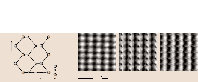
The (110) surface of the III–V semiconductor indium arsenide exhibits both atomic
species in the top layer (see Fig. 5.18a). Therefore, this sample is well suited to
study the chemical sensitivity of force microscopy [121]. In Fig. 5.18b, the usually
observed atomic-scale contrast on InAs(110) is displayed. As predicted, the arsenic
atoms, which are shifted by 80 pm above the indium layer due to the (1 ×1) re-
laxation, are imaged as protrusions. While this general appearance was similar for
most tips, two other distinctively different contrasts were also observed: a second
protrusion (c) and a sharp depression (d). The arrangement of these two features
corresponds well to the zigzag configuration of the indium and arsenic atoms along
the [1
10]-direction. A sound explanation would be as follows: the contrast usually
obtained with one feature per surface unit cell corresponds to a silicon-terminated
tip, as predicted by simulations. A different atomic species at the tip apex, however,
1 nm
[1
-
10]
[00
-
1]
a)
In 1st layer
In 2nd layer
As 1st layer
As 2nd layer
[1
-
10]
[00
-
1]
b) c) d)
Fig. 5.18. The structure of InAs(110) as seen from above (a) and three FM-AFM images of
this surface obtained with different tips at 14 K (b)–(d). In (b), only the arsenic atoms are im-
aged as protrusions, as predicted for a silicon tip. The two features in (c)and(d) corresponds
to the zigzag arrangement of the indium and arsenic atoms. Since force microscopy is sen-
sitive to short-range chemical forces, the appearance of the indium atoms can be associated
with a chemically different tip apex
5 Low-Temperature Scanning Probe Microscopy 211
can result in a very different charge redistribution. Since the atomic-scale contrast
is due to a chemical interaction, the two other contrasts would then correspond to
a tip that has been accidentally contaminated with sample material (an arsenic or
indium-terminated tip apex). Nevertheless, this explanation has not yet been veri-
fied by simulations for this material.
Tip-Induced Atomic Relaxation
Schwarz et al. [121] were able to visualize directly the predicted tip-induced relax-
ation during atomic-scale imaging near a point defect. Figure 5.19 shows two FM-
AFM images of the same point defect recorded with different constant frequency
shifts on InAs(110), i.e., the tip was closer to the surface in (b) compared to (a).
The arsenic atoms are imaged as protrusions with the silicon tip used. From the
symmetry of the defect, an indium-site defect can be inferred, since the distance-
dependent contrast is consistent with what is expected for an indium vacancy. This
expectation is based on calculations performed for the similar III–V semiconductor
GaP(110), where the two surface gallium atoms around a P-vacancy were found to
z (pm)
[1
-
10]
direction (nm)
0.0
15
10
5
0
–5
–10
–15
0.5 1.0 1.5 2.0
z (pm)
[1
-
10]
direction (nm)
0.0
30
20
10
0
–10
0.5 1.0 1.5 2.0
1 nm
[001]
[1
-
10]
a)
b)
Fig. 5.19. Two FM-AFM im-
ages of the identical indium-
site point defect (presumably
an indium vacancy) recorded
at 14 K. If the tip is relatively
far away, the theoretically
predicted inward relaxation
of two arsenic atoms adjacent
to an indium vacancy is visi-
ble (a). At a closer tip–sample
distance (b), the two arsenic
atoms are pulled farther to-
ward the tip compared to the
other arsenic atoms, since
they have only two instead of
three bonds