Beer F.P., Johnston E.R., DeWolf J.T., Mazurek D.F. Mechanics of Materials
Подождите немного. Документ загружается.

Apago PDF Enhancer
617
Problems
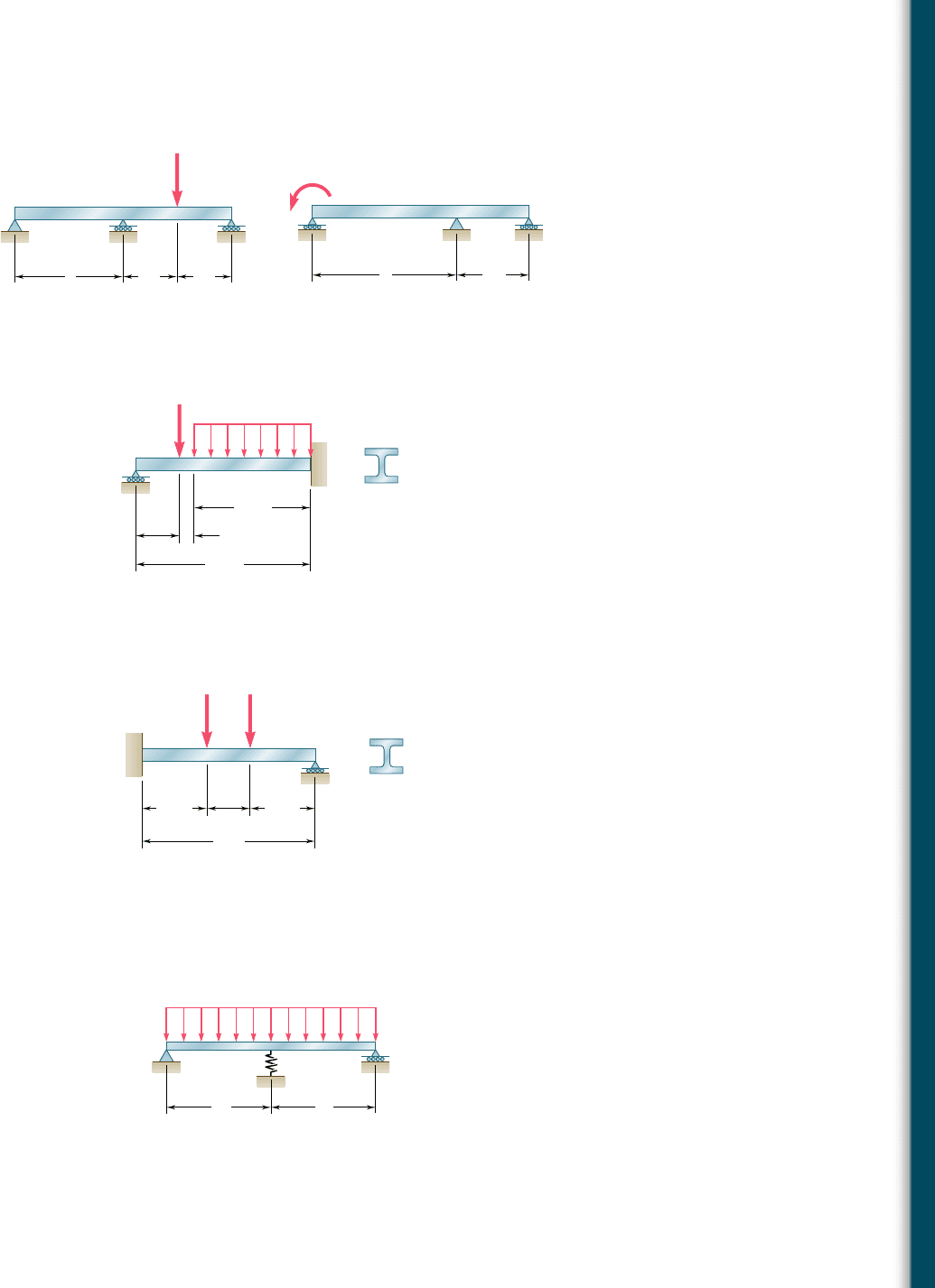
9.154 Determine the reaction at the roller support and draw the bending-
moment diagram for the beam and loading shown.
9.151 and 9.152 For the beam and loading shown, determine the
reaction at each support.
A
P
C
B
LL/2 L/2
Fig. P9.151
M
0
AC
B
LL/2
Fig. P9.152
9.153 Determine the reaction at the roller support and draw the bending-
moment diagram for the beam and loading shown.
75 kN
40 kN/m
A
DE B
2.4 m
0.3 m
0.9 m
3.6 m
W310 44.5
Fig. P9.153
4.5 ft 4.5 ft
3 ft
12 ft
W14 38
AD E
B
30 kips 10 kips
Fig. P9.154
k
C
w
A
B
LL
Fig. P9.155 and P9.156
9.155 For the beam and loading shown, determine the spring constant k
for which the force in the spring is equal to one-third of the total
load on the beam.
9.156 For the beam and loading shown, determine the spring constant k
for which the bending moment at B is M
B
5 2wL
2
/10.
bee80288_ch09_548-629.indd Page 617 10/30/10 11:27:25 PM user-f499bee80288_ch09_548-629.indd Page 617 10/30/10 11:27:25 PM user-f499 /Users/user-f499/Desktop/Temp Work/Don't Delete Job/MHDQ251:Beer:201/ch09/Users/user-f499/Desktop/Temp Work/Don't Delete Job/MHDQ251:Beer:201/ch09
Apago PDF Enhancer
618
REVIEW AND SUMMARY
This chapter was devoted to the determination of slopes and deflec-
tions of beams under transverse loadings. Two approaches were used.
First we used a mathematical method based on the method of inte-
gration of a differential equation to get the slopes and deflections at
any point along the beam. We then used the moment-area method
to find the slopes and deflections at a given point along the beam.
Particular emphasis was placed on the computation of the maximum
deflection of a beam under a given loading. We also applied these
methods for determining deflections to the analysis of indeterminate
beams, those in which the number of reactions at the supports
exceeds the number of equilibrium equations available to determine
these unknowns.
We noted in Sec. 9.2 that Eq. (4.21) of Sec. 4.4, which relates the
curvature 1yr of the neutral surface and the bending moment M in
a prismatic beam in pure bending, can be applied to a beam under
a transverse loading, but that both M and 1yr will vary from section
to section. Denoting by x the distance from the left end of the beam,
we wrote
1
r
5
M1x2
EI
(9.1)
This equation enabled us to determine the radius of curvature of the
neutral surface for any value of x and to draw some general conclu-
sions regarding the shape of the deformed beam.
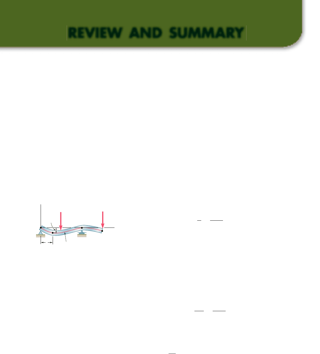
In Sec. 9.3, we discussed how to obtain a relation between the
deflection y of a beam, measured at a given point Q, and the distance
x of that point from some fixed origin (Fig. 9.70). Such a relation
defines the elastic curve of a beam. Expressing the curvature 1yr in
terms of the derivatives of the function y(x) and substituting into
(9.1), we obtained the following second-order linear differential
equation:
d
2
y
dx
2
5
M1x2
EI
(9.4)
Integrating this equation twice, we obtained the following expres-
sions defining the slope u(x) 5 dyydx and the deflection y(x),
respectively:
E
I
dy
dx
5
#
x
0
M1x2 dx 1 C
1
(9.5)
EI y 5
#
x
0
dx
#
x
0
M1x2 dx 1 C
1
x 1 C
2
(9.6)
Deformation of a beam under
transverse loading
C
y
x
y
A
D
Q
x
Elastic
curve
P
2
P
1
Fig. 9.70
bee80288_ch09_548-629.indd Page 618 10/30/10 11:27:36 PM user-f499bee80288_ch09_548-629.indd Page 618 10/30/10 11:27:36 PM user-f499 /Users/user-f499/Desktop/Temp Work/Don't Delete Job/MHDQ251:Beer:201/ch09/Users/user-f499/Desktop/Temp Work/Don't Delete Job/MHDQ251:Beer:201/ch09
Apago PDF Enhancer
619
The product EI is known as the flexural rigidity of the beam; C
1
and
C
2
are two constants of integration that can be determined from the
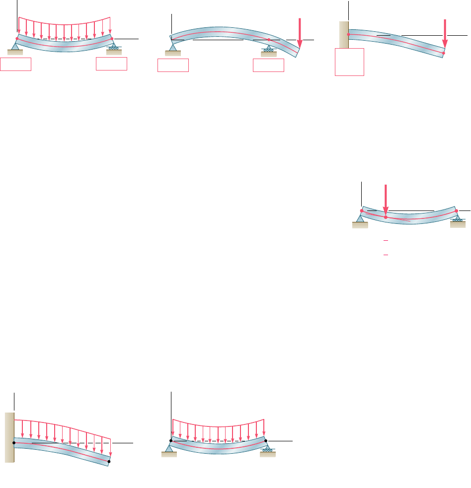
boundary conditions imposed on the beam by its supports (Fig. 9.71)
[Example 9.01]. The maximum deflection can then be obtained by
determining the value of x for which the slope is zero and the cor-
responding value of y [Example 9.02, Sample Prob. 9.1].
Boundary conditions
D
B
A
y
x
x 0, y
1
0
x L, y
2
0
[
[
[
[
x
L,
1
1
4
[
[
x L, y
1
y
2
2
1
4
[
[
P
Fig. 9.72
B
x
A
y
(a) Cantilever beam
[ y
A
0]
[
A
0]
[V
B
0]
[M
B
0]
B
A
y
(b) Simply supported beam
[ y
A
0]
x
[ y
B
0]
[M
B
0][M
A
0]
Fig. 9.73 Boundary conditions for beams carrying a distributed load.
Review and Summary
Fig. 9.71 Boundary conditions for statically determinate beams.
P
y
y
A
0
B
A
x
(b) Overhanging beam
y
B
0
B
A
y
(a) Simply supported beam
y
A
0
y
B
0
x
P
y
B
x
A
(c) Cantilever beam
y
A
0
A
0
When the loading is such that different analytical functions are
required to represent the bending moment in various portions of the
beam, then different differential equations are also required, leading
to different functions representing the slope u(x) and the deflection
y(x) in the various portions of the beam. In the case of the beam
and loading considered in Example 9.03 (Fig. 9.72), two differential
equations were required, one for the portion of beam AD and the
other for the portion DB. The first equation yielded the functions u
1
and y
1
, and the second the functions u
2
and y
2
. Altogether, four
constants of integration had to be determined; two were obtained by
writing that the deflections at A and B were zero, and the other two
by expressing that the portions of beam AD and DB had the same
slope and the same deflection at D.
We observed in Sec. 9.4 that in the case of a beam supporting
a distributed load w(x), the elastic curve can be determined directly
from w(x) through four successive integrations yielding V, M, u, and
y in that order. For the cantilever beam of Fig. 9.73a and the simply
supported beam of Fig. 9.73b, the resulting four constants of integra-
tion can be determined from the four boundary conditions indicated
in each part of the figure [Example 9.04, Sample Prob. 9.2].
Elastic curve defined by
different functions
bee80288_ch09_548-629.indd Page 619 10/30/10 11:27:44 PM user-f499bee80288_ch09_548-629.indd Page 619 10/30/10 11:27:44 PM user-f499 /Users/user-f499/Desktop/Temp Work/Don't Delete Job/MHDQ251:Beer:201/ch09/Users/user-f499/Desktop/Temp Work/Don't Delete Job/MHDQ251:Beer:201/ch09
Apago PDF Enhancer
620
Defl ection of Beams
Fig. 9.74
B
A
A
L
(a)
B
wL
A
x
A
y
L
L/2
(b)
M
A
B
w
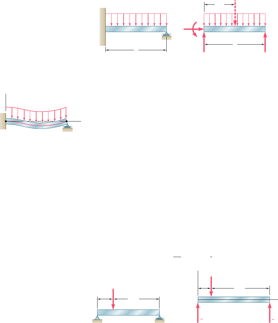
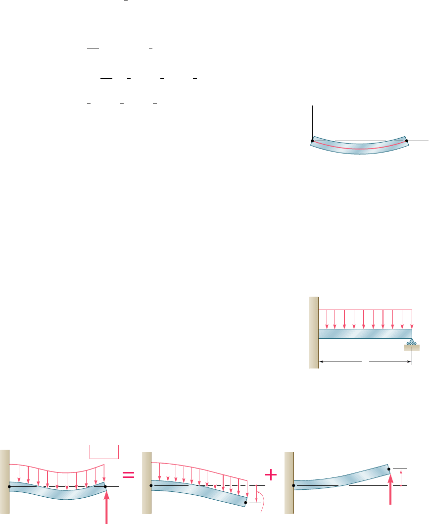
In Sec. 9.5, we discussed statically indeterminate beams, i.e., beams
supported in such a way that the reactions at the supports involved
four or more unknowns. Since only three equilibrium equations are
available to determine these unknowns, the equilibrium equations
had to be supplemented by equations obtained from the boundary
conditions imposed by the supports. In the case of the beam of
Fig 9.74, we noted that the reactions at the supports involved four
Statically indeterminate beams
w
B
x
x 0, 0
[]
x L, y 0
[]
x 0, y 0
[]
A
y
Fig. 9.75
P
B
D
A
3L/4
L/4
Fig. 9.76
A
D
B
x
y
P
L/4
3L/4
3
4
P
1
4
P
Fig. 9.77
Use of singularity functions
unknowns, namely, M
A
, A
x
, A
y
, and B. Such a beam is said to be
indeterminate to the first degree. (If five unknowns were involved,
the beam would be indeterminate to the second degree.) Expressing
the bending moment M(x) in terms of the four unknowns and inte-
grating twice [Example 9.05], we determined the slope u(x) and the
deflection y(x) in terms of the same unknowns and the constants of
integration C
1
and C
2
. The six unknowns involved in this computa-
tion were obtained by solving simultaneously the three equilibrium
equations for the free body of Fig. 9.74b and the three equations
expressing that u 5 0, y 5 0 for x 5 0, and that y 5 0 for x 5 L
(Fig. 9.75) [see also Sample Prob. 9.3].
The integration method provides an effective way for determining the
slope and deflection at any point of a prismatic beam, as long as the
bending moment M can be represented by a single analytical function.
However, when several functions are required to represent M over the
entire length of the beam, this method can become quite laborious,
since it requires matching slopes and deflections at every transition
point. We saw in Sec. 9.6 that the use of singularity functions (previ-
ously introduced in Sec. 5.5) considerably simplifies the determination
of u and y at any point of the beam. Considering again the beam of
Example 9.03 (Fig. 9.76) and drawing its free-body diagram (Fig. 9.77),
we expressed the shear at any point of the beam as
V1x25
3
P
4
2 P Hx 2
1
4
LI
0
bee80288_ch09_548-629.indd Page 620 11/18/10 8:58:44 PM user-f499bee80288_ch09_548-629.indd Page 620 11/18/10 8:58:44 PM user-f499 /Users/user-f499/Desktop/Temp Work/Don't Delete Job/MHDQ251:Beer:201/ch09/Users/user-f499/Desktop/Temp Work/Don't Delete Job/MHDQ251:Beer:201/ch09
Apago PDF Enhancer
621
where the step function
H
x 2
1
4
L
I
0
is equal to zero when the quantity
inside the brackets H I is negative, and equal to one otherwise. Inte-
grating three times, we obtained successively
M1x25
3P
4
x 2 PHx 2
1
4
LI
(9.44)
EI u 5 EI
d
y
d
x
5
3
8
Px
2
2
1
2
PHx 2
1
4
LI
2
1 C
1
(9.46)
EI y 5
1
8
Px
3
2
1
6
P
H
x 2
1
4
L
I
3
1 C
1
x 1 C
2
(9.47)
where the brackets H I should be replaced by zero when the quantity
inside is negative, and by ordinary parentheses otherwise. The con-
stants C
1
and C
2
were determined from the boundary conditions
shown in Fig. 9.78 [Example 9.06; Sample Probs. 9.4, 9.5, and 9.6].
The next section was devoted to the method of superposition, which
consists of determining separately, and then adding, the slope and
deflection caused by the various loads applied to a beam [Sec. 9.7].
This procedure was facilitated by the use of the table of Appendix D,
which gives the slopes and deflections of beams for various loadings
and types of support [Example 9.07, Sample Prob. 9.7].
The method of superposition can be used effectively with statically
indeterminate beams [Sec. 9.8]. In the case of the beam of Exam-
ple 9.08 (Fig. 9.79), which involves four unknown reactions and is
thus indeterminate to the first degree, the reaction at B was con-
sidered as redundant and the beam was released from that sup-
port. Treating the reaction R
B
as an unknown load and considering
separately the deflections caused at B by the given distributed load
and by R
B
, we wrote that the sum of these deflections was zero
(Fig. 9.80). The equation obtained was solved for R
B
[see also
Sample Prob. 9.8]. In the case of a beam indeterminate to the
second degree, i.e., with reactions at the supports involving five
unknowns, two reactions must be designated as redundant, and
the corresponding supports must be eliminated or modified accord-
ingly [Sample Prob. 9.9].
Review and Summary
B
A
y
x
x 0, y 0
[]
x L, y 0
[]
Fig. 9.78
Method of superposition
Statically indeterminate beams
by superposition
We next studied the determination of deflections and slopes of beams
using the moment-area method. In order to derive the moment-area
theorems [Sec. 9.9], we first drew a diagram representing the varia-
tion along the beam of the quantity MyEI obtained by dividing the
B
(y
B
)
R
R
B
w
w
B
AA
B
y
B
0
(y
B
)
w
R
B
A
(a)(b)(c)
Fig. 9.80
First moment-area theorem
B
A
L
w
Fig. 9.79
bee80288_ch09_548-629.indd Page 621 10/30/10 11:28:01 PM user-f499bee80288_ch09_548-629.indd Page 621 10/30/10 11:28:01 PM user-f499 /Users/user-f499/Desktop/Temp Work/Don't Delete Job/MHDQ251:Beer:201/ch09/Users/user-f499/Desktop/Temp Work/Don't Delete Job/MHDQ251:Beer:201/ch09
Apago PDF Enhancer
622
Defl ection of Beams
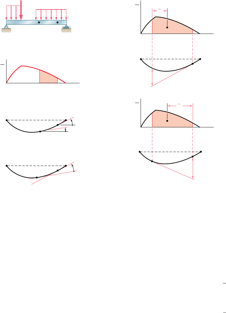
bending moment M by the flexural rigidity EI (Fig. 9.81). We then
derived the first moment-area theorem, which may be stated as fol-
lows: The area under the (MyEI) diagram between two points is
equal to the angle between the tangents to the elastic curve drawn
at these points. Considering tangents at C and D, we wrote
u
DyC
5 area under (MyEI) diagram
between C and D
(9.56)
B
A
B
C
t
C/D
t
D/C
D
D
A
C'
D'
C
BCDA
M
EI
x
BCDA
M
E
I
x
x
2
(a)
(b)
x
1
Fig. 9.82 Second moment-area theorem.
Again using the (MyEI) diagram and a sketch of the deflected beam
(Fig. 9.82), we drew a tangent at point D and considered the vertical
distance t
CyD
, which is called the tangential deviation of C with
respect to D. We then derived the second moment-area theorem,
which may be stated as follows: The tangential deviation t
CyD
of C
with respect to D is equal to the first moment with respect to a verti-
cal axis through C of the area under the (MyEI) diagram between C
and D. We were careful to distinguish between the tangential devia-
tion of C with respect to D (Fig. 9.82a).
t
C
y
D
5
1
area between C and D
2
x
1
(9.59)
and the tangential deviation of D with respect to C (Fig. 9.82b):
t
D
y
C
5
1
area between C and D
2
x
2
(9.60)
B
C
D
A
(c)
D
C
Fig. 9.81 First moment-area theorem.
(d)
B
C
D
A
D/C
BCDA
M
EI
x
(b)
B
CD
A
(a)
Second moment-area theorem
bee80288_ch09_548-629.indd Page 622 10/30/10 11:28:07 PM user-f499bee80288_ch09_548-629.indd Page 622 10/30/10 11:28:07 PM user-f499 /Users/user-f499/Desktop/Temp Work/Don't Delete Job/MHDQ251:Beer:201/ch09/Users/user-f499/Desktop/Temp Work/Don't Delete Job/MHDQ251:Beer:201/ch09
Apago PDF Enhancer
623
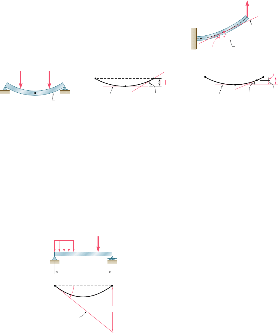
In Sec. 9.10 we learned to determine the slope and deflection at
points of cantilever beams and beams with symmetric loadings.
For cantilever beams, the tangent at the fixed support is horizontal
(Fig. 9.83); and for symmetrically loaded beams, the tangent is
horizontal at the midpoint C of the beam (Fig. 9.84). Using the
horizontal tangent as a reference tangent, we were able to deter-
mine slopes and deflections by using, respectively, the first and
second moment-area theorems [Example 9.09, Sample Probs. 9.10
and 9.11]. We noted that to find a deflection that is not a tangen-
tial deviation (Fig. 9.84c), it is necessary to first determine which
tangential deviations can be combined to obtain the desired
deflection.
Review and Summary
Cantilever Beams
Beams with symmetric loadings
D
=
D/A
y
D
= t
D/A
Reference tangent
Tangent at D
D
A
P
Fig. 9.83
C
B
A
P
Horizontal
(a)
P
C
B
y
max
t
B/C
A
Reference tangent
(b)
B/CB
C
B
D
t
D/C
t
B/C
y
D
A
Reference tangent
(c)
D/CD
Fig. 9.84
In many cases the application of the moment-area theorems is sim-
plified if we consider the effect of each load separately [Sec. 9.11].
To do this we drew the (MyEI) diagram by parts by drawing a sepa-
rate (MyEI) diagram for each load. The areas and the moments of
areas under the several diagrams could then be added to determine
slopes and tangential deviations for the original beam and loading
[Examples 9.10 and 9.11].
In Sec. 9.12 we expanded the use of the moment-area method to cover
beams with unsymmetric loadings. Observing that locating a horizontal
tangent is usually not possible, we selected a reference tangent at one
of the beam supports, since the slope of that tangent can be readily
determined. For example, for the beam and loading shown in Fig. 9.85,
the slope of the tangent at A can be obtained by computing the
Bending-moment diagram by parts
Unsymmetric loadings
P
Reference
tangent
A
w
B
A
B
L
(a)
(b)
A
t
B/A
Fig. 9.85
bee80288_ch09_548-629.indd Page 623 10/30/10 11:28:12 PM user-f499bee80288_ch09_548-629.indd Page 623 10/30/10 11:28:12 PM user-f499 /Users/user-f499/Desktop/Temp Work/Don't Delete Job/MHDQ251:Beer:201/ch09/Users/user-f499/Desktop/Temp Work/Don't Delete Job/MHDQ251:Beer:201/ch09
Apago PDF Enhancer
624
Defl ection of Beams
tangential deviation t
ByA
and dividing it by the distance L between the
supports A and B. Then, using both moment-area theorems and sim-
ple geometry, we could determine the slope and deflection at any
point of the beam [Example 9.12, Sample Prob. 9.12].
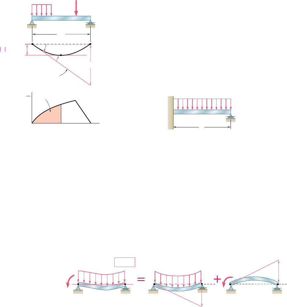
The maximum deflection of an unsymmetrically loaded beam gener-
ally does not occur at midspan. The approach indicated in the preced-
ing paragraph was used to determine point K where the maximum
deflection occurs and the magnitude of that deflection [Sec. 9.13].
Observing that the slope at K is zero (Fig. 9.86), we concluded that
u
KyA
5 2u
A
. Recalling the first moment-area theorem, we determined
the location of K by measuring under the (M/EI) diagram an area
equal to u
KyA
. The maximum deflection was then obtained by comput-
ing the tangential deviation t
AyK
[Sample Probs. 9.12 and 9.13].
In the last section of the chapter [Sec. 9.14] we applied the moment-
area method to the analysis of statically indeterminate beams. Since
the reactions for the beam and loading shown in Fig. 9.87 cannot be
Maximum deflection
P
A
A
w
B
B
K
L
0
0
(a)
AKB
x
(b)
A
K
K/A
A
K/A
t
B/A
Reference
target
Area
M
EI
y
max
t
A /K
Fig. 9.86
B
w
A
L
Fig. 9.87
determined by statics alone, we designated one of the reactions of
the beam as redundant (M
A
in Fig. 9.88a) and considered the redun-
dant reaction as an unknown load. The tangential deviation of B with
respect to A was considered separately for the distributed load
(Fig. 9.88b) and for the redundant reaction (Fig. 9.88c). Expressing
that under the combined action of the distributed load and of the
couple M
A
the tangential deviation of B with respect to A must be
zero, we wrote
t
B
y
A
5
1
t
B
y
A
2
w
1
1
t
B
y
A
2
M
5 0
From this expression we determined the magnitude of the redundant
reaction M
A
[Example 9.14, Sample Prob. 9.14].
A
A
w
w
B
B
AB
M
A
M
A
t
B/A
0
B''
B'
(t
B/A
)
w
(t
B/A
)
M
(a)(b)(c)
Fig. 9.88
Statically indeterminate beams
bee80288_ch09_548-629.indd Page 624 10/30/10 11:28:19 PM user-f499bee80288_ch09_548-629.indd Page 624 10/30/10 11:28:19 PM user-f499 /Users/user-f499/Desktop/Temp Work/Don't Delete Job/MHDQ251:Beer:201/ch09/Users/user-f499/Desktop/Temp Work/Don't Delete Job/MHDQ251:Beer:201/ch09
Apago PDF Enhancer
625
REVIEW PROBLEMS
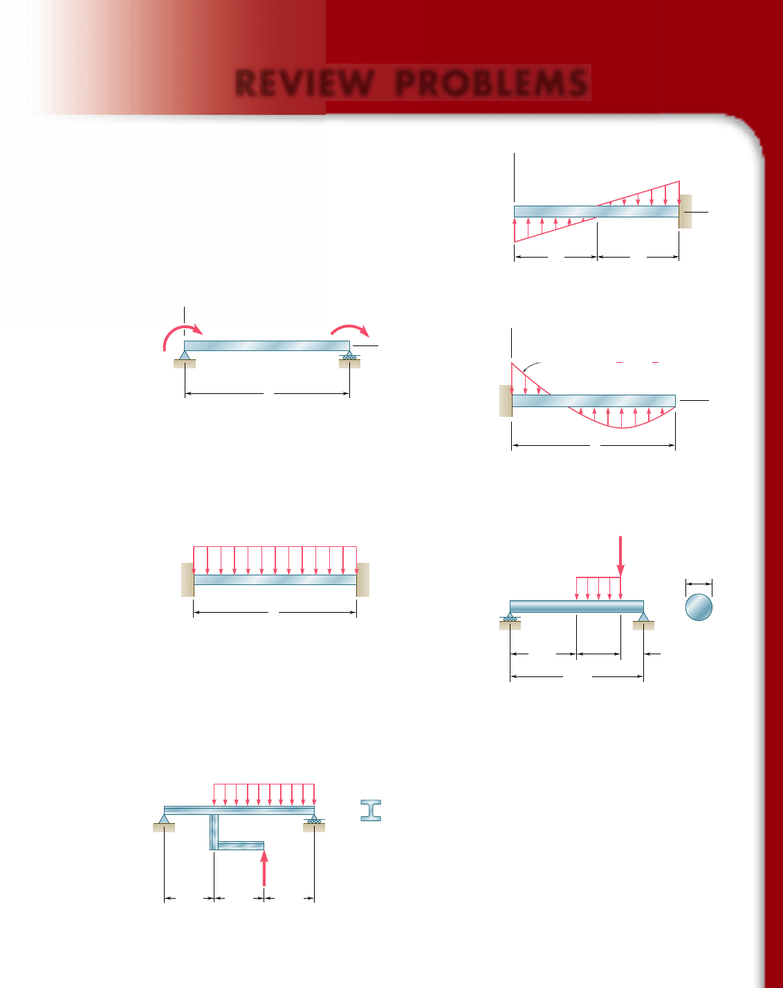
9.157 For the loading shown, determine (a) the equation of the elastic
curve for the cantilever beam AB, (b) the deflection at the free
end, (c) the slope at the free end.
9.158 (a) Determine the location and magnitude of the maximum absolute
deflection in AB between A and the center of the beam. (b) Assum-
ing that beam AB is a W18 3 76 rolled shape, M
0
5 150 kip ? ft
and E 5 29 3 10
6
psi, determine the maximum allowable length L
so that the maximum deflection does not exceed 0.05 in.
B
A
C
y
w
0
w
0
L/2 L/2
x
Fig. P9.157
y
x
M
0
M
0
B
A
L
Fig. P9.158
9.159 For the beam and loading shown, determine (a) the equation of
the elastic curve, (b) the deflection at the free end.
9.160 Determine the reaction at A and draw the bending moment dia-
gram for the beam and loading shown.
w w
0
[1 4( ) 3( )
2
]
x
L
x
L
y
A
x
L
B
Fig. P9.159
AB
w
L
Fig. P9.160
9.161 For the beam and loading shown, determine (a) the slope at end A,
(b) the deflection at point B. Use E 5 29 3 10
6
psi.
9.162 The rigid bar BDE is welded at point B to the rolled-steel beam
AC. For the loading shown, determine (a) the slope at point A,
(b) the deflection at point B. Use E 5 200 GPa.
AD
1.25 in.
24 in.
16 in.
48 in.
8 in.
200 lb
10 lb/in.
BC
Fig. P9.161
C
B
E
D
A
1.5 m 1.5 m 1.5 m
W410 85
20 kN/m
60 kN
Fig. P9.162
bee80288_ch09_548-629.indd Page 625 10/30/10 11:28:26 PM user-f499bee80288_ch09_548-629.indd Page 625 10/30/10 11:28:26 PM user-f499 /Users/user-f499/Desktop/Temp Work/Don't Delete Job/MHDQ251:Beer:201/ch09/Users/user-f499/Desktop/Temp Work/Don't Delete Job/MHDQ251:Beer:201/ch09
Apago PDF Enhancer
626
Defl ection of Beams
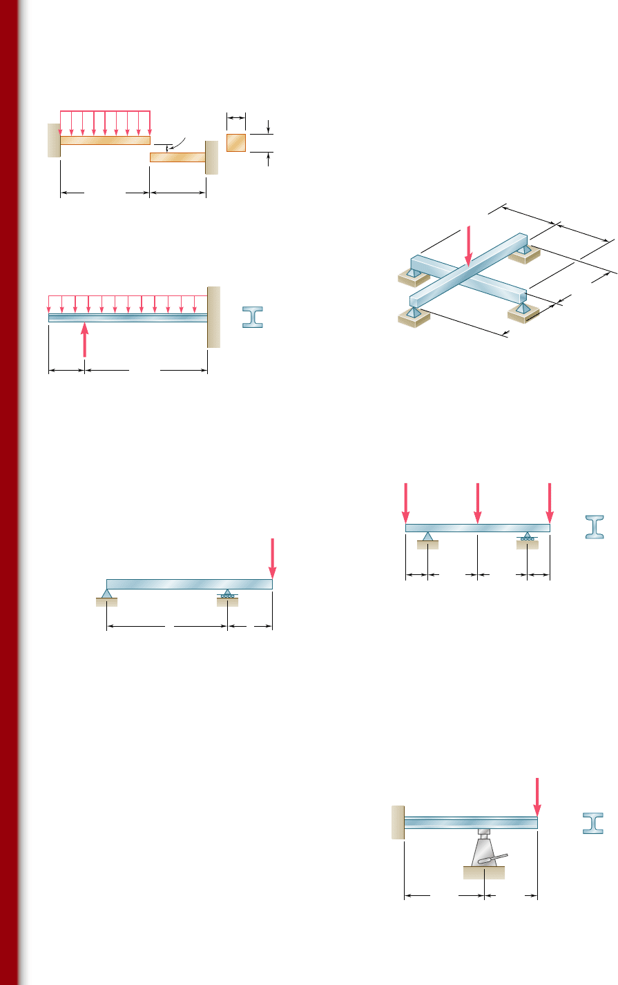
9.163 Before the uniformly distributed load w is applied, a gap, d
0
5
1.2 mm, exists between the ends of the cantilever bars AB and
CD. Knowing that E 5 105 GPa and w 5 30 kN/m, determine
(a) the reaction at A, (b) the reaction at D.
9.164 For the loading shown, and knowing that beams AB and DE
have the same flexural rigidity, determine the reaction (a) at B,
(b) at E.
400 mm
250 mm
50 mm
50 mm
w
A
C
D
B
0
Fig. P9.163
P 6 kips
a 4 ft
a 4 ft
b 5 ft
D
A
C
E
B
b 5 ft
Fig. P9.164
9.165 For the cantilever beam and loading shown, determine (a) the slope
at point A, (b) the deflection at point A. Use E 5 200 GPa.
9.166 Knowing that the magnitude of the load P is 7 kips, determine (a)
the slope at end A, (b) the deflection at end A, (c) the deflection
at midpoint C of the beam. Use E 5 29 3 10
6
psi.
A
26 kN/m
C
B
0.5 m
2.2 m
W250 28.4
18 kN
Fig. P9.165
S6 12.5
1.5 kips 1.5 kipsP
A
E
BC D
2 ft 2 ft
4.5 ft 4.5 ft
Fig. P9.166
9.167 For the beam and loading shown, determine (a) the slope at point
C, (b) the deflection at point C.
9.168 A hydraulic jack can be used to raise point B of the cantilever
beam ABC. The beam was originally straight, horizontal, and
unloaded. A 20-kN load was then applied at point C, causing this
point to move down. Determine (a) how much point B should be
raised to return point C to its original position, (b) the final value
of the reaction at B. Use E 5 200 GPa.
AC
P
La
B
Fig. P9.167
B
C
A
W130 23.8
20 kN
1.8 m 1.2 m
Fig. P9.168
bee80288_ch09_548-629.indd Page 626 10/30/10 11:29:25 PM user-f499bee80288_ch09_548-629.indd Page 626 10/30/10 11:29:25 PM user-f499 /Users/user-f499/Desktop/Temp Work/Don't Delete Job/MHDQ251:Beer:201/ch09/Users/user-f499/Desktop/Temp Work/Don't Delete Job/MHDQ251:Beer:201/ch09
