Astakhov V. Tribology of Metal Cutting
Подождите немного. Документ загружается.


Basics, Definitions and Cutting Tool Geometry 407
kind as well as local and global interference are considered. The interference mentioned
can result in interference mark on the tool body, at the best, or it leads to rapid tool
damage and makes the cutting operation impossible.
A3.4 Cutting edge radius
As discussed above, the tool designer apparently has the rake and the flank angle design
parameters to optimize the tool performance. Practice of tool production, however, proves
that this is not always the case.
The problem is that the edge is assumed to be very sharp compared to the thickness of the
layer to be removed and, therefore, the actual rake angle is the same as that assigned by
the tool drawing. This is true for more than 80% of the metalworking operations, where
the thickness of the layer to be removed is 10–20-fold greater than the radius of the
cutting edge. As such, this radius is simply neglected and the cutting tool is considered
to be perfectly sharp. Unfortunately, the same cannot be applied to many finishing and
hard turning operations with a very “light” uncut chip thickness. One may wonder: what
seems to be the problem?
To understand the problem, consider the model of cutting shown in Fig. 3.46 (Chapter 3),
where a cutting tool having a radius of the cutting edge ρ
ce
is shown. The tool is set to
remove the uncut chip thickness t
1
. Due to the radius of the cutting edge, this uncut chip
thickness is divided into two parts: the actual uncut chip thickness t
a
, which is removed
by cutting and thus turns into the chip, and the deformed uncut chip thickness h
1
which is
ploughed under the tool. When the ratio t
1
/ρ
1
≥ 10, the effect of ρ
1
is small so the tool is
considered to be perfectly sharp. However, when t
1
/ρ
1
< 10, the relative impact due to
ploughing by the rounded cutting edge becomes significant and thus cannot be ignored.
Naturally, the cutting process ceases at certain t
1
/ρ
1
turning to be pure burnishing or
ploughing.
It is discussed in Chapter 3 that the cutting process ceases and the layer to be removed
undergoes plastic deformation similar to burnishing when (Eq. (3.69))
h
1
ρ
ce
≤ 0.5 −
τ
in
σ
y
, (A19)
where σ
y
is the yield strength of the work material and τ
in
is the shear strength of adhesion
bonds between work and tool materials.
The shear strength of adhesion bonds primarily depends on the mechanical properties of
the work material and the contact temperature.
Equation (A19) allows us to determine the limiting uncut chip thickness (t
1−lim
= h
1
)
for a given combination of work and tool materials. However, one should note that the
cutting process becomes unstable even before this limiting value is reached. It can be
easily detected by excessive vibrations, poor surface finish and reduced tool life.

408 Tribology of Metal Cutting
Example 2
Problem: Determine the minimum feed that can be used in the machining of 303
stainless steel with the depth of cut t
1
= 2 mm by a carbide insert KC850 (Kennametal)
having the cutting edge angle κ
r
= 72
◦
, nose radius r
1
= 0.8 mm and cutting edge radius
ρ
ce
= 0.055 mm.
Solution: For the steel considered τ
in
= 145 MPa and σ
y
= 264 MPa. From Eq. (A19),
the limiting uncut chip thickness is calculated as
t
1−lim
= ρ
ce
0.5 −
τ
in
σ
y
= 0.055
0.5 −
145
264
= 0.025 mm
Given conditions indicate that we deal with the case shown in Fig. A7(a). Therefore,
we can calculate the critical cutting feed using iteration method for Eq. (A8)
f
cr
= t
1−lim
c
1
1
sin arctan
(
c
1
/
([
1 − e
1
(1 − cos κ
r
)
]
cot κ
r
+e
1
(sin κ
r
+g
1
)
))
= 0.025 ×c
1
1
sin arctan
c
1
[
1 − 0.4(1 − cos 72)
]
cot 72 +0.4(sin 72 +g
1
)
,
where
g
1
=
f
cr
2r
n
=
f
cr
2 × 0.8
,e
1
=
r
n
t
1
=
0.8
2
= 0.4 and
c
1
= 1 −e
1
1 −
1 − g
1
= 1 −0.4
1 −
1 − g
1
.
The minimum cutting feed f
cr
= 0.039 mm/rev was calculated using MathCAD.
To verify that the case considered corresponds to Fig. A7(a), we can check the conditions
set by Eq. (A7)
t
1
= 2 ≥ r
n
(
1 − cos κ
r
)
= 0.8
1 − cos 72
◦
= 0.55 : valid
f
cr
= 0.039 ≤ 2r
n
sin κ
r1
= 2 ×0.8 ×sin 72 = 1.52 : valid
A3.5 Inclination angle
Although the sense and sign of the inclination angle λ
s
is clearly shown in Fig. A4
and it is defined earlier as the angle between the cutting edge and the reference plane,
experience shows that there are certain difficulties and confusions in understanding this
angle.
Figure A11 aims to clarify the issue. The inclination angle λ
s
is measured in a plane
H which is perpendicular to the reference plane xy and passes through the tool tip
Basics, Definitions and Cutting Tool Geometry 409
z
y
x
+l
s
−l
s
1
2
H
1
1
2
2
l
s
= 0°
Fig. A11. Sense of the sign of the inclination angle.
(nose point) 1. Numbers 1 and 2 designate the ends of the cutting edge. As such, if
the tool tip 1 is located below point 2, the inclination angle λ
s
is positive; if points 1 and
2 are at the same level, λ
s
= 0; and when the tool tip 1 is located above point 2, then
the inclination angle λ
s
is negative.
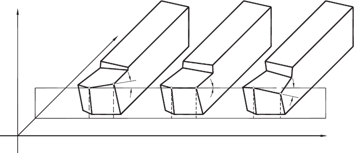
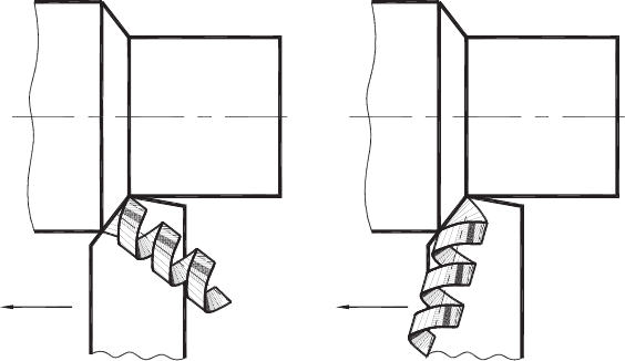
The sign of the inclination angle defines the chip-flow direction, as shown in Fig. A12.
When λ
s
is positive, the chip flows to the right and when λ
s
is negative, the chip flows
to the left. The direction of chip flow, however, is defined not only by λ
s
, but also by
the cutting edge angle κ
r
. These two angles define the spatial location of the tool cutting
edge. In turn, the spatial location of the cutting edge constrains the location of these
planes, since the cutting edge is the line of intersection of the rake and flank planes.
The complete location of the rake plane is then defined when the normal rake angle γ
n
is known and the location of the flank planes is fully defined when the normal flank
angle α
n
is known.
Simple relationships exist among the angles considered in the tool-in-hand system. These
relationships have been derived assuming that the tool-side rake angle γ
f
, the tool-back
rake angle γ
p
and the tool cutting edge angle κ
r
are the basic angles for the tool face, and
the tool side clearance angle α
f
, the tool back clearance angle α
p
, and the tool cutting
edge angle κ
r
are the basic angles for the tool flank
tan λ
s
= sin κ
r
tan γ
p
−cos κ
r
tan γ
f
(A20)
tan γ
n
= cos λ
s
tan γ
o
(A21)
tan γ
o
= cos κ
r
tan γ
p
+sin κ
r
tan γ
f
(A22)
cos α
n
= cos λ
s
cot α
o
(A23)
cot α
o
= cos κ
r
cot α
p
+sin κ
r
cot α
f
(A24)
410 Tribology of Metal Cutting
+l
s
−l
s
ff
Fig. A12. Influence of sign of the inclination angle on the direction of chip flow.
It must be stated, however, that some of these relationships apply only when the cutting
edge angle κ
r
is less than 90
◦
. Nowadays, it is a common practice to use cutting tools
having κ
r
greater than 90
◦
. Moreover, most of the drills are made in the same way.
For these tools, the following relationships are valid
tan λ
s
=−sin κ
r
tan γ
p
−cos κ
r
tan γ
f
(A25)
tan γ
o
= cos λ
s
tan γ
o
(A26)
tan γ
o
=−cos κ
r
tan γ
p
+sin κ
r
tan γ
f
(A27)
cot α
n
= cos λ
s
cot α
o
(A28)
cot α
o
=−cos κ
r
cot α
p
+sin κ
r
cot α
f
(A29)
A4 Determination of Uncut Chip Thickness for a General Case
Section A3 defines the uncut chip thickness for the simplest case where a single-point
cutting tool is used for turning (Fig. A7). Because the uncut chip thickness defines to a
large extent the tribological conditions of any cutting operation, its proper determination
for the whole variety of the cutting tools should be provided. Unfortunately, none of
the books contains such a material, and so tool designers, manufacturing specialists and
practitioners in the field have no reference to turn to in the determination of uncut chip
thickness for many cutting operations besides turning, milling and drilling. As a result,
the determination of the true uncut chip thickness is not carried out in the design and
analysis of many tools.
Further considerations are based on the method proposed by Rodin [6] and further
developed by Astakhov et al. [7,8].
Basics, Definitions and Cutting Tool Geometry 411
The uncut chip thickness for any machining operation at a given point of the cutting
edge is determined as
t
1
= f cos χ
f
, (A30)
where χ
f
is the angle between the feed direction and the normal to the tool cutting edge
plane at the point of the cutting edge considered. This angle can be considered as the
tool cutting edge angle in the tool-in-use system.
Generally, angle χ
f
is considered in the 3D plane containing the vectors of the feed
motion and the normal to the tool cutting edge plane at the point considered. Note that
this plane is always the main reference plane in the tool-in-use system of consideration
of the tool geometry. The direction of feed for a tool working with several feed motions
is determined by the vector summation of the directions of all these feeds. This should
not present any problem as these directions are well known.
As angle χ
f
is between the feed direction f and the normal N to the tool cutting edge
plane at the point of the cutting edge considered, the angle between these two vectors is
determined as
cos χ
f
=
f × N
f
N
(A31)
and thus the uncut chip thickness is then calculated as
t
1
=
f × N
N
(A32)
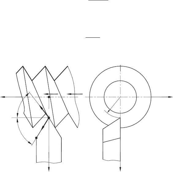
x
z
y
B
A
y
w
R
i
v
f
d
f
k
r
A
f
a
Fig. A13. Determining the uncut chip thickness in thread cutting.

412 Tribology of Metal Cutting
Consider the determination of the uncut chip thickness t
1
in a thread-cutting operation
as an example of the use of the proposed methodology. A model of this operation is
shown in Fig. A13. A thread cutting is fed incrementally after each pass by feed f in the
direction of f so the cutting edge AB does the entire cutting. In this model, vector a is a
unit vector along the cutting edge so it always lies in the tool cutting edge plane in any
system of consideration. The xyz coordinate system is set, as shown in Fig. A13. In this
coordinate system, the vector of the cutting feed f is determined by its projection on the
corresponding coordinate axes as
f = if cos δ
f
−jf sin δ
f
(A33)
and unit vector a as
a = i cos κ
r
+j sin κ
r
(A34)
If R
i
is the location radius of point A of the cutting edge, the velocity of this point in its
spiral motion is
v
A
= iν
f
+ω × R
i
= iν
f
+kωR
i
, (A35)
where ν
f
is the velocity of the tool in the x direction. It is understood that
ν
f
= knp, (A36)
where k is the number of starts of the thread being cut, n is the number of revolutions
per second of the vortices (rpm/60) and p is the thread pitch.
A normal S to the tool cutting edge plane in the tool-in-use system is determined by the
cross product of vectors v
A
and a located in this plane as
N = a ×v
A
=
'
'
'
'
'
'
ijk
cos κ
r
sin κ
r
0
ν
f
0 ωR
i
'
'
'
'
'
'
= iωR
i
sin κ
r
+jωR
i
cos κ
r
−kν
f
sin κ
r
(A37)
and its modulus
N
= ω
R
2
i
+h
2
h
sin
2
κ
r
, (A38)
where h
h
= ν
f
/ω is the helix parameter.
Using Eq. (A32), one can obtain
t
1
=
ωR
i
sin κ
r
cos δ
f
+ωR
i
f cos κ
r
sin δ
f
ω
R
2
i
+h
2
h
sin
2
κ
r
=
fR
i
sin
κ
r
+δ
f
R
2
i
+h
2
h
sin
2
κ
r
(A39)
Basics, Definitions and Cutting Tool Geometry 413
As shown, the uncut chip thickness varies along the cutting edge because radius R
i
differs for each of its point. In a particular case of bar turning, δ
f
= 0 and h
h
= 0, thus
Eq. (A39) becomes
t
1
= f sin κ
r
(A40)
which is the same as Eq. (A3) obtained earlier for this case.
References
[1] Astakhov, V.P., Metal Cutting Mechanics, CRC Press, Boca Raton, USA, 1998.
[2] Oxley, P.L.B., Mechanics of Machining: An Analytical Approach to Assessing Machinability,
John Wiley & Sons, New York, USA, 1989.
[3] Klushin, M.I., Metal Cutting: Basics of Plastic Deformation of the Layer Been Removed,
Mashgiz, Moscow, Russia, 1958.
[4] Stabler, G.V., The chip flow law and its consequences. In Proceedings of the 5th International
MTDR Conference, 1964.
[5] Colwell, L.V., Predicting the angle of chip flow for single point cutting tools, Transactions
of the ASME, 76 (1954), 199–202.
[6] Rodin, P.R., The Basics of Shape Formation by Cutting (in Russian), Visha Skola, Kyev,
Ukraine, 1972.
[7] Astakhov, V.P., Galitsky, V.V., Osman, M.O.M., A novel approach to the design of self
piloting drills. Part 1. Geometry of the cutting tip and grinding process, ASME Journal of
Engineering for Industry, 117 (1995), 453–463.
[8] Astakhov, V.P., Galitsky, V.V., Osman, M.O.M., A novel approach to the design of
self-piloting drills with external chip removal. Part 2: Bottom clearance topology and
experimental results, ASME Journal of Engineering for Industry, 117 (1995), 464–474.

APPENDIX B
Experimental Determination of the Chip
Compression Ratio (CCR)
B1 General Experimental Techniques
Although a number of experimental methods for the determination of the chip compres-
sion ratio (CCR) were known to researchers, modern books and other publications on
metal cutting do not consider any of them because CCR is not regarded as an important
parameter in metal cutting studies. Because it is argued in this book that major tribologi-
cal parameters and characteristics of metal cutting correlate with CCR, a need to present
a few common experimental methods for the determination of CCR is felt.
The simplest method is to measure the chip thickness and then calculate CCR as
ζ = t
2
/t
1
, (B1)
where t
2
is the chip thickness and t
1
is the uncut chip thickness.
However this is not always possible because the chip: (a) might have a saw-toothed free
surface and (b) be very small and 3D-curved.
The second method is the weighing method. A small (5–10 mm long) straight piece of
the chip is separated from the rest of the chip. Then, its length L
c
and width d
w1
are
measured. When the piece of the chip selected for the study is not straight, a computer
vision system available nowadays in most shops is used to measure its length properly.
Then, it is weighed so its weight G
ch
(N) is determined. The chip thickness is then
calculated as
t
2
=
G
ch
d
w1
L
c
ρ
w
g
, (B2)
where ρ
w
is the density of the work material (kg/m
3
) and g = 9.81 m/s
2
is the gravity
constant.
414
Experimental Determination of the Chip Compression Ratio (CCR) 415
For finishing operations when the depth of cut is shallow, it becomes rather difficult to
measure the width of the chip. CCR is determined in this case using the ratio of the chip
and the uncut chip cross-sectional areas, A
ch
and A
w
, respectively, i.e.
ζ =
A
ch
A
w
(B3)
As such, the cross-sectional area of the chip is determined using the weighing method as
A
ch
=
G
ch
L
c
ρ
w
g
(B4)
and the cross-sectional area of the uncut chip is determined as
A
w
= d
w
f, (B5)
where d
w
is the depth of cut and f is the cutting feed.
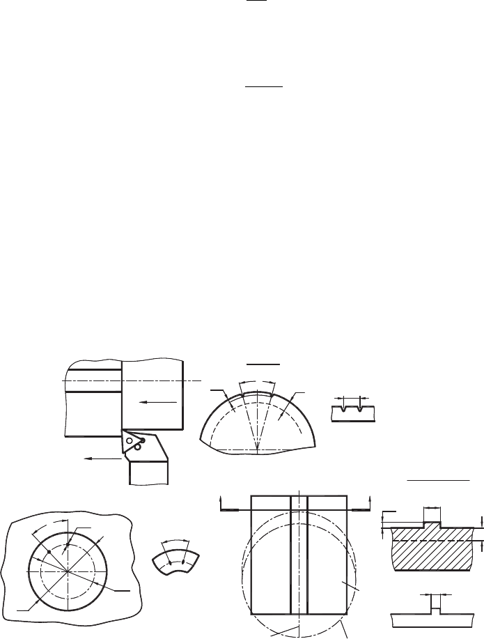
The third method is the direct method, which is applicable in turning, milling, drilling and
other common machining operations. The essence of this method is that the workpiece
is “marked” before cutting and then the resultant marks on the chip are compared with
the original marks. The realization of this method for longitudinal turning is shown in
Fig. B1(a). As shown, two longitudinal grooves are made on the outer surface of the
Tool
(c) MILLING
Fragment of the chip
ØD
Ød
Workpiece
Ød
1
(b) DRILLING
L
l
Trajectory of cutters
Axis of the tool
Fragment of the chip
L
c
A
Workpiece
L
c
SECTION A-A
A
h
1
h
L
l
A
Workpiece
f
Fragment of the chip
(a) TURNING
Workpiece
h
w
View A
L
g1
d
w
L
g2
Fig. B1. Practical methods of determining CCR.

416 Tribology of Metal Cutting
workpiece before testing and the arc distance between these grooves L
g1
is measured.
After the test, a chip section with these marks can be easily found and the distance L
g2
is measured. CCR is then determined as
ζ = L
g1
/L
g2
(B6)
The realization of the method discussed to measure CCR in drilling is shown in
Fig. B1(b). Two small holes of diameter d
1
are drilled as shown in Fig. B1(b) along
the trajectory of the point of the drill cutting edge. Diameter d
2
is smaller than that (D)
of the would-be-hole. The arc distance L
g1
between the centers of these holes is mea-
sured. After the test, a chip fragment having marks from the two holes is found and the
arc distance L
g2
between their centers is measured at high magnification using an optical
comparator or a computer vision system. Using Eq. (B6), CCR is determined.
The realization of the discussed method for face milling is shown in Fig. B1(c). As
shown, the surface of the workpiece is made with a step having width L
g1
=3–6 mm
and height which is 4–6 times smaller that the depth of the cut, i.e. d
w
/h
w
= 4–6. After
the test, the width L
g2
is measured and CCR is determined using Eq. (B6). Shifting the
position of the axes of the tool and the workpiece, one can determine CCR under a wide
range of uncut chip thickness.
B2 Design of Experiment
Approximation of the dependence of CCR on the factor “vt
1
” (the Peclet criterion) can
be accomplished using a simple test program consisting of only two runs. For example,
for the test results of which shown in Fig. 2.8, the following simple design of experiment
can be utilized. Table B1 shows the plan of tests.
Using these test results, CCR can be approximated as follows:
ζ = ζ
0
vt
1
√
(
vt
1
)
2
/
(
vt
1
)
1
x
ζ
, (B7)
where
ζ
0
=
ζ
1
ζ
2
=
√
2.60 × 1.93 = 2.24 (B8)
Table B1. Plan and test results.
Test number (i) 10
3
vt
1
(m
2
/s) CCR (ζ
i
)
1 0.25 2.60
2 1.85 1.93