Astakhov V. Tribology of Metal Cutting
Подождите немного. Документ загружается.

Basics, Definitions and Cutting Tool Geometry 397
SECTION N−N
VIEW S
SECTION P−P
N
N
(Plane P
O
)
(Plane P
p
)
(Plane P)
n
(Plane P)
s
SECTION O−O
F
O
P
P
F
O
(Plane P
f
)
SECTION F−F
S
2
0
1
3
O'
SECTION O'−O'
(Plane O')
a
1o
k
r
k
r1
y
r
a
f
a
o
a
p
a
n
b
n
g
n
l
s
+l
−l
b
p
g
p
b
o
g
o
+g
−g
b
f
g
f
O'
P
f
P
r
P
s
P
s
P
p
P
r
P
r
P
r
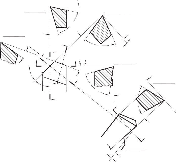
Fig. A4. Tool angles in the tool-in-hand system.
of rake, wedge and clearance angles is 90
◦
, i.e.
γ
p
+β
p
+α
p
= γ
n
+β
n
+α
n
= γ
o
+β
o
+α
o
= γ
f
+β
f
+α
f
= 90
◦
(A1)
• The orientation and inclination of the cutting edge are specified in the tool cutting
edge plane P
s
. In this plane, the cutting edge inclination angle λ
s
is the angle
between the cutting edge and the reference plane. This angle is defined as always
being acute and positive if the cutting edge, when viewed in a direction away from
the selected point at the tool corner being considered, lies on the opposite side of
the reference plane from the direction of primary motion. This angle can be defined
at any point of the cutting edge. The sign of the inclination angle is well defined
in Fig. A4.
• The definition of the tool cutting edge angle κ
r
is shown in Fig. A2. It is defined
as the acute angle that the tool cutting edge plane makes with the working plane

398 Tribology of Metal Cutting
assumed and is measured in the reference plane P
r
. It can also be defined as the acute
angle between the projection of the main cutting edge into the reference plane and
the x direction. Angle κ
r
is always positive and it is measured in a counter-clockwise
direction from the position of the working plane assumed.
• Similarly, the tool minor (end) cutting edge angle κ
r1
is the acute angle that the minor
cutting edge plane makes with the working plane assumed and is measured in the
reference plane P
r
. It can also be defined as the acute angle between the projection of
the minor (end) cutting edge into the reference plane and the x direction (Fig. A4).
Angle κ
r1
is always positive (including zero) and it is measured in a clockwise
direction from the position of the working plane assumed.
A3.1 Cutting edge angle
The tool cutting edge angle significantly affects the cutting process because, for a given
feed and cutting depth, it defines the uncut chip thickness, width of cut, and thus tool
life. The physical background of this phenomenon can be explained as follows: when κ
r
decreases, the chip width increases correspondingly because the active part of the cutting
edge increases. The latter results in improved heat removal from the tool and hence the
tool life increases. For example, if the tool life of a High Speed Steel (HSS) face milling
tool having κ
r
= 60
◦
is taken to be 100%, when κ
r
= 30
◦
, its tool life is 190%, and
when κ
r
= 10
◦
its tool life is 650%. Even more profound effect of κ
r
is observed in
the machining with single-point cutting tools. For example, in rough turning of carbon
steels, the change of κ
r
from 45 to 30
◦
sometimes leads to a fivefold increase in the
tool life.
The reduction of κ
r
, however, has its drawbacks. One of them is the corresponding
increase of the radial component, (F
y
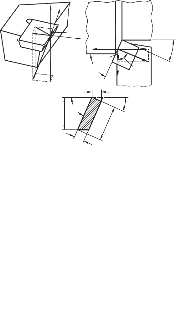
) of the cutting force. Figure A5(a) shows that in
general, the cutting force, (R) is a 3D vector and thus it can be resolved into three orthogo-
nal components, namely, the power (tangential, torque) component (F
z
) (often referred to
in literature on metal cutting as (F
T
), axial component (F
x
) and radial component (F
y
).
For simplicity, these are often called tangential, axial and radial forces, respectively.
As shown in Fig. A5(b), the radial and axial forces are related as
F
x
F
y
= tan κ
r
(A2)
From Eq. (A2), lowering κ
r
from 45 to 20
◦
results in more than twofold increase in
the radial force that increases the bending force acting on the workpiece and thus may
reduce the accuracy of machining because the rigidity of the workpiece varies along its
length. When the workpiece is machined between the centers, an increased radial force
causes the so-called barreling, and when the workpiece is clamped only in the chuck,
tapering may occur. Besides, since lowering κ
r
leads to an increased radial force, this
force often causes vibrations so that the advantages of small cutting edge angle may not
become too profound.
Basics, Definitions and Cutting Tool Geometry 399
R
F
x
y
x
x
y
F
z
R
xy
F
y
Fx
b
1
a
1
f
d
w
(a) (b)
(c)
z
k
r
k
r
k
r1
k
r
k
r1
F
y
R
xy
Fig. A5. The cutting force system and the uncut chip thickness for a single-point cutting tool.
Another drawback of small κ
r
is the reduction in the uncut chip thickness t
1
. From
Fig. A5(c)
t
1
= f sin κ
r
, (A3)
where f is the cutting feed per revolution.
It follows from Eq. (A3) that under a given feed f, the uncut chip thickness can be varied
in a wide range by changing the angle κ
r
. When this angle becomes zero, the uncut chip
thickness is also zero (no cutting) and when κ
r
= 90
◦
, the uncut chip thickness reaches
its maximum becoming t
1
= f as in orthogonal cutting. Hence, t
1
∈
(
0,f
)
.
The following equation for the uncut chip area correlates the feed (f ) and the depth of
cut (d
w
) with the uncut chip thickness (t
1
) and non-orthogonal chip width d
w1
= b
1
d
w
f = t
1
d
w1
= A
w
(A4)
and
t
1
= f sin κ
r
(A5)
d
w1
=
d
w
sin κ
r
, (A6)
where A
w
is the cross-sectional area of the uncut chip.
400 Tribology of Metal Cutting
From Eq. (A4), under a given feed and depth of cut, any change of t
1
causes a
corresponding change of d
w1
= b
1
. As shown, when t
1
∈
(
0,f
)
, the chip width
d
w1
∈
(
∞,d
w
)
.
In general, the specific cutting force (the force that is acting on the unit length of the
cutting edge) is proportional to the uncut chip thickness. For this reason, the uncut chip
thickness is often referred to as the chip load in literature on metal cutting. As discussed
earlier in this book, this parameter is of great importance in determining many tribological
characteristics of the cutting process. A rule of thumb here is: the smaller the chip load,
the higher the tool life, and vice versa. However, there is the minimum uncut chip
thickness (under other given cutting parameters) below which the opposite effect is true.
Two factors primarily limit the minimum allowable uncut chip thickness:
• Decreasing the uncut chip thickness, one should increase the width of cut according
to Eq. (A4). When t
1
→ 0, d
w1
→∞, i.e. the length of the cutting edge should be
increased to infinity. Obviously, this is not practical.
• Uncut chip thickness cannot be less than the radius of the cutting edge.
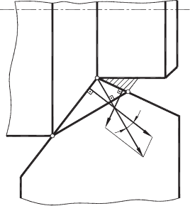
Real cutting cannot be regarded as free cutting because real tools always have more than
one cutting edge engaged in cutting. There have been a number of attempts to allow
for the inter-influence of the neighboring cutting edges in determining the direction of
chip flow. They are well summarized in [2]. Klushin [3] and Stabler [4] suggested the
determination of the true uncut chip thickness t
1T
in a plane perpendicular to the direction
of chip flow while the true uncut chip width b
1T
(
d
w1T
)
in the perpendicular direction
and equal to the length of the segment AB, which joins the ends of the major and minor
cutting edges engaged in cutting, as shown in Fig. A6. In this figure, the directions
AC and BC are orthogonal chip flow directions of the major and minor cutting edges,
respectively, and the direction AB is the resultant chip-flow direction. The angle between
AC and AB is referred to as the chip-flow angle η
ch
. The segment AB is often referred
A
C
B
AC
BC
AB
h
ch
Fig. A6. Chip-flow direction.
Basics, Definitions and Cutting Tool Geometry 401
d
w
d
w
d
w
r
n
k
r
k
r
k
r
k
r1
k
r1
k
r1
k
r1
k
r
k
r
r
n
d
w
f
O
(a) (b)
(c) (d)
f
f
1.1f
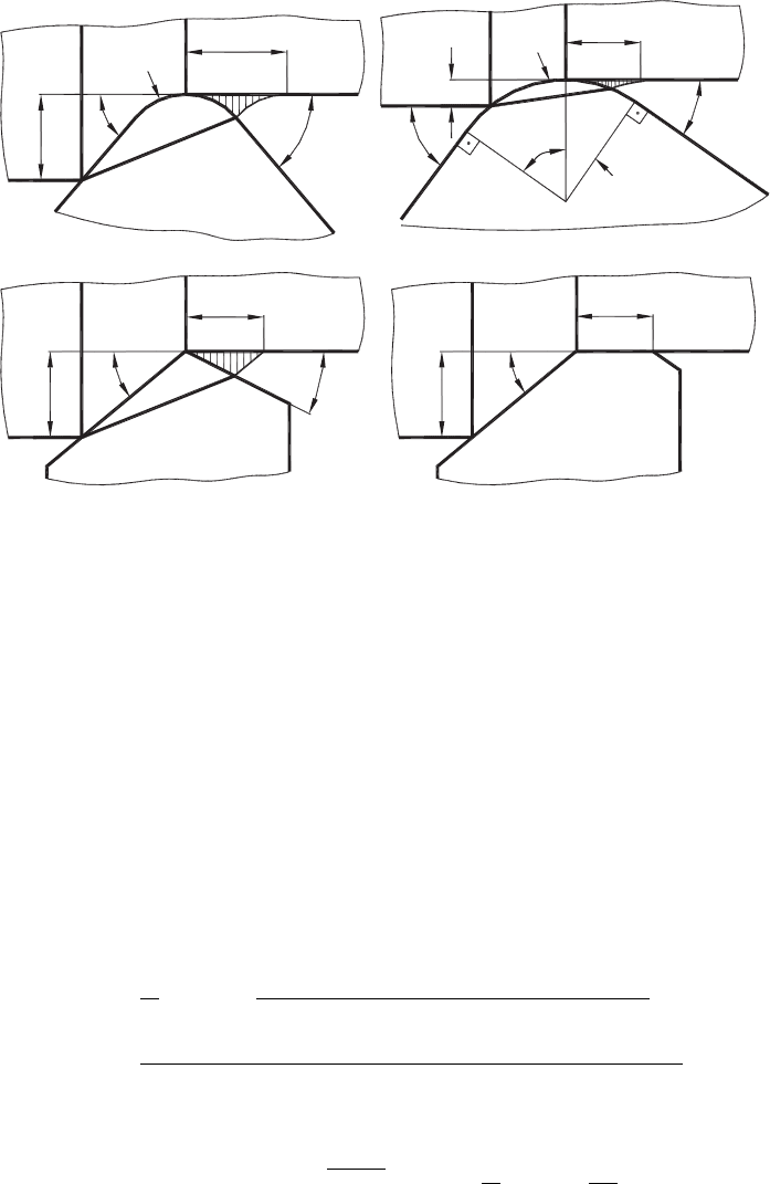
Fig. A7. Four basic configurations in non-free cutting.
to as the equivalent cutting edge, as suggested by Colwell [5]. Therefore, in non-free
cutting, the uncut chip thickness depends on the orientation of the equivalent cutting edge.
Figure A7 presents four basic configurations in non-free cutting. The first configuration,
shown in Fig. A7(a), represents the most common single-point tools in use today. The cut-
ting tool is made with a nose radius r
n
and set so that the depth of cut is greater than the
nose radius.
If the following relationships are justified
d
w
≥ r
n
(
1 − cos κ
r
)
,f≤ 2r
n
sin κ
r1
(A7)
then the formulas for calculation of t
1T
and b
1T
are as follows:
t
1T
=
f
c
1
sin arctan
c
1
[
1 − e
1
(1 − cos κ
r
)
]
cot κ
r
+e
1
(sin κ
r
+g
1
)
(A8)
b
1T
=
c
1
d
w
sin arctan {c
1
/
([
1 − e
1
(1 − cos κ
r
)
]
cot κ
r
+e
1
(sin κ
r
+g
1
)
)
}
, (A9)
where
c
1
= 1 −e
1
1 −
1 − g
1
,e
1
=
r
n
t
1
,g
1
=
f
2r
n
(A10)

402 Tribology of Metal Cutting
The second configuration, shown in Fig. A7(b) is similar to the first except that only the
radius part of the cutting edge is engaged in cutting. If the following relationships are
justified
d
w
<r
n
(
1 − cos κ
r
)
,f≤ 2r
n
sin κ
r1
(A11)
the formulas for calculation of t
1T
and b
1T
are as follows:
t
1T
=
f
c
1
sin arctan
c
1
√
2e
1
−1 +e
1
g
1
(A12)
b
1T
=
c
1
d
w
sin arctan
c
1
/(e
1
g
1
+
√
2e
1
−1)
(A13)
In the third configuration (Fig. A7(c)), the nose radius is rather small compared to the
depth of cut, so that only the straight parts of the major and minor cutting edges are
considered. Then the formulas for calculation of t
1T
and b
1T
are as follows:
t
1T
=
f
q
1
sin arctan
q
1
1 + cot κ
r
−q
1
(A14)
b
1T
=
c
1
d
w
sin arctan
c
1
/(e
1
g
1
+
√
2e
1
−1)
, (A15)
where
q
1
= 1 −
f
d
w
1
cot κ
r
+cot κ
r1
(A16)
In the fourth configuration (Fig. A7(d)), the nose radius is rather small so that only
the straight parts of the major and minor cutting edges are considered. To improve the
machined surface finish, the minor cutting edge is positioned parallel to the axis of
rotation of the workpiece so that κ
r1
= 0. As such, the length of the minor cutting edge
is usually selected to be equal to 1.1f . The formulas for calculation of t
1T
and b
1T
are
as follows:
t
1T
= f sin arctan
1
cot κ
r
+2.2e
1
g
1
(A17)
b
1T
=
d
w
sin arctan
(
1/(cot κ
r
+2.2e
1
g
1
)
)
(A18)
Although the fourth configuration has been known for many years and its advantages are
well documented, its implementation has often been accompanied by vibration and thus
was restricted by the rigidity of the machine tools. Only recently, when machine tools
became rigid enough, it became possible to use tools with such geometry on rigid milling
machines. Cutting inserts of such geometry known now as wiper inserts are widely used
in practice.
Basics, Definitions and Cutting Tool Geometry 403
In operation, “wiper” technology is designed to improve surface finishes in milling
applications. It works by positioning an insert with a flat, just-below-the-other ordinary
parallel land inserts on a face mill. As the “wiper” passes through the cut, it smoothens
the surface. It allows using much higher feed rate without compromising surface finish
of the machined areas.
Example 1
Problem: Find the uncut chip area for the major and minor cutting edges (assuming
κ
r1
= 0
◦
) when feed f = 0.3mm/rev, depth of cut d
w
= 2 mm for tools having the
cutting edge angle κ
r
= 45
◦
and κ
r
= 85
◦
.
Solution: Using Eq. (A4), we can calculate the uncut chip area of the major cutting
edge for the first and second tools because the depth of cut and the cutting feed are the
same for both the tools
A
w
= f × d
w
= 0.3 ×2 = 0.6mm
2
Using Eq. (A25), we can calculate the maximum uncut chip area for the minor cut-
ting edge
For the first tool
A
wm
= 0.5f
2
tan κ
r
= 0.5 ×0.3
2
tan 45
◦
= 0.045 mm
2
For the second tool
A
wm
= 0.5f
2
tan κ
r
= 0.5 ×0.3
2
tan 85
◦
= 0.515 mm
2
As shown, the uncut chip area for the minor cutting edge for the second tool is almost
the same as that for the major cutting edge. Therefore, the cutting forces generated due
to the minor cutting edge cannot be ignored because the cross-sectional area of the uncut
chip for this edge is almost the same like the major cutting edge. Moreover, since this
edge is not meant to cut any significant amount of the work material, its cutting geometry
(the rake and the flank angles) are not selected to perform efficient cutting, so the cutting
forces generated by this edge are normally much higher than those generated by the
major cutting edge under the same conditions. The problem gets worsened when the
depth of cut decreases.
A3.2 Rake angle
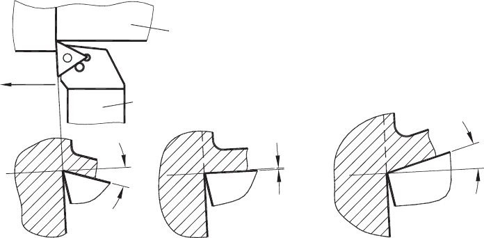
Rake angles are three types, positive, zero (sometimes referred to as neutral) and negative,
as shown in Figs. A8(a)–(c), respectively. It is generally accepted that the increase in
the rake angle reduces the horsepower consumption per unit volume of the layer being
removed as 1% per degree starting from γ =−20
◦
. As a result, the cutting force and
tool–chip contact temperature change in approximately the same way. So, it seems to be
reasonable to select a high positive rake angle for practical cutting operations. Everyday
404 Tribology of Metal Cutting
f
Workpiece
Tool
+g
−
g
g = 0°
(a) (b) (c)
Fig. A8. (a) Positive, (b) zero and (c) negative rake angles.
machining practice, however, shows that there are number of drawbacks in increasing
the rake angle.
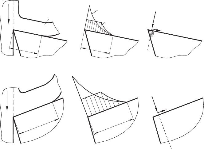
The main drawback is that the strength of the cutting wedge decreases when the rake
angle increases. The reason for that is illustrated in Fig. A9. When cutting with a positive
rake angle, as shown in Fig. A9(a), the interaction of the tool rake face with the moving
chip results in certain distributions of the normal and tangential stresses over the contact
length l
c
. As discussed in Chapter 3, these distributions can be represented in terms
of the corresponding resultant normal N and tangential F forces acting on the cutting
wedge. As shown, the normal force N causes the bending of the tip of the cutting
wedge. The presence of bending significantly reduces the strength of the cutting wedge
causing its chipping. Moreover, the tool–chip contact area reduces with the rake angle,
so the point of application of the normal force shifts closer to the cutting edge. On the
contrary, when cutting with a tool having a negative rake angle (Fig. A9(b)), the normal
force N acting on the tool rake face does not cause the bending mentioned. Instead,
it results in the compression of the tool material. Because hard tool materials have very
high compressive strength, the strength of the cutting edge in this case is much higher
although the normal force N is greater than that for tool with positive rake angles. This is
particularly true when superhard tool materials (for example, Poly-Crystalline Diamond
(PCD) and Cubic Boron Nitride (CBN)) are used in interrupted and hard turning. It has
to be mentioned, however, that rapid development of PCD and CBN materials led to
their increased bending strength, so tools with positive geometries are used in machining
of high-silicon aluminum alloys in the automotive industry even in interrupted cutting
operations.
Another important drawback is that the region of the maximum contact temperature at
the tool–chip interface shifts toward the cutting edge when the rake angle is increased,
which lowers the tool life, as discussed in Chapter 3.
Basics, Definitions and Cutting Tool Geometry 405
Chip
Cutting
direction
F
N
s
max
s
max
t
max
t
max
Normal contact stress
Tangential contact stress
m
Tool
(a)
(b)
Cutting
direction
N
F
l
c
l
c
l
c
l
c
Fig. A9. Forces acting on the cutting edge having: (a) positive rake angle and (b) negative rake
angle.
Realistically, the rake angle is not an independent variable in the tool geometry selection
process because the effect of rake angle depends upon other parameters of the cutting
tool geometry and the cutting process. Moreover, the necessity of applying chip breakers
of different shapes often dictates the resulting rake angle rather than other parameters of
the cutting process like tool life, power consumption and cutting force.
A3.3 Flank angle
If the Flank (relief) angle α = 0
◦
, then the flank surface of the cutting tool is in full
contact with the workpiece. As such, due to spring-back of the workpiece material, there
is significant friction force in such a contact that leads usually to tool breakage. The flank
angle affects the performance of the cutting tool mainly through decreasing the rubbing
on the tool’s flank surfaces. When the uncut chip thickness is small (less than 0.02 mm),
this angle should be in the range of 30–35
◦
to achieve maximum tool life.
The flank angle directly affects the tool life. When angle α increases, wedge angle β
decreases, as shown from Fig. A4. As such, the strength of the region adjacent to the
cutting edge decreases as well as heat dissipates through the tool. These factors lower
the tool life. On the other hand, by increasing the flank angle the following advantages
are obtained:
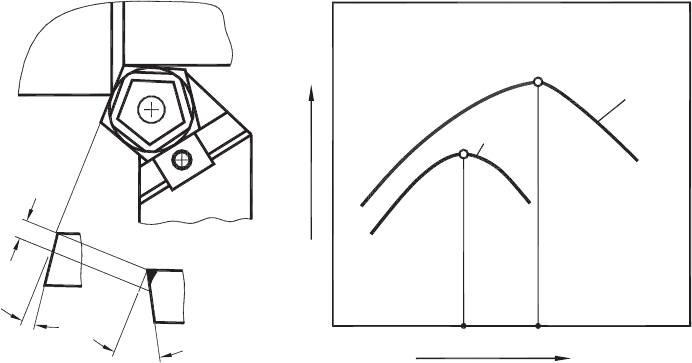
406 Tribology of Metal Cutting
VB
8°
30°
t
1−2
> t
1−1
Flank Angle
Tool Life
T
t
1−1
t
1−2
a
1
a
2
α
(a) (b)
Fig. A10. Influence of flank angle: (a) the difference in the worn tool materials under the same
flank wear for different flank angles and (b) on tool life.
The cutting edge radius decreases with the flank angle that leads to corresponding
decrease in the frictional and deformation components of the flank force. This effect
becomes noticeable in cutting with small feeds. As a result, less heat is generated that
leads to an increase in tool life.
As the flank angle becomes larger, more tool material should be removed (worn out)
to reach the same flank wear as shown in Fig. A10(a). As a result, the tool life
increases.
Due to such contradictive effects, the influence of flank angle on tool life always has a
well-defined maximum, as shown in Fig. A10(b).
One has to remember the most important rule in assigning the flank angle which reads:
“The actual flank angle should not be less than 3
◦
” (exceptions are some form of tools
such as broaching tools, gear hobs and shapers, shaving tools, etc.). Otherwise the
normal cutting operation can be hardly performed due to vibrations and excessive tool
wear. Therefore, it is very important to estimate the actual flank angle(s) accounting
for the tool design, its installation in a machine, its working conditions including the
direction of the prime and feed motions. One should also remember that in machining
difficult-to-machine materials, a 2
◦
change in the flank angle might change the tool life
by twice. The same can be said about the integrity of machined surfaces.
If the actual flank angle is close to 0
◦
or negative, the interference of the tool flank surface
and the workpiece takes place, i.e. the tool profile runs into the workpiece profile. In the
theory of profile generation by cutting tools, the interference of the first, second and third