Astakhov V. Tribology of Metal Cutting
Подождите немного. Документ загружается.

Cutting Tool Wear, Tool Life and Cutting Tool Physical Resource 257
0
0.2
f (mm/rev) f (mm/rev)
0.03
0.3 0.4 0.5
1
2
3
0.05
0.07
0.09
600
700
800
900
q(°)
h
pl
h
s
q
0.07
0.05
0.03
0.01
h
pl
0.1 0.2 0.3
d
w
=1.00 mm
d
w
=2.00 mm
d
w
=0.50 mm
h
s
(µm/10
3
sm
2
)
h
pl
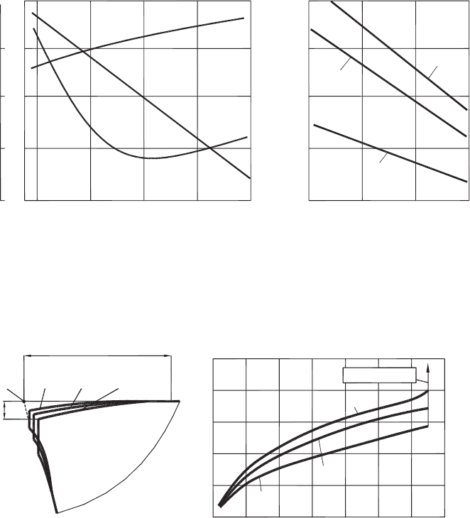
Fig. 4.24. Influence of cutting feed in turning stainless steel AISI 303: (a) on cutting temperature,
tool wear rate and h
pl
criterion, tool material – carbide M20 (92% WC, 8% Co), ν = 72 m/min,
d
w
= 5 mm, γ = 15
◦
, α = α
1
= 10
◦
, κ
r
= 45
◦
, κ
r1
= 10
◦
, r
n
= 1 mm, (b) on h
pl
criterion under
the optimal cutting temperature θ
opt
= 850
◦
C, tool material – carbide P10 (14% TiC, 8% Co),
γ = 10
◦
, α = α
1
= 10
◦
, κ
r
= 45
◦
, κ
r1
= 10
◦
, r
n
= 1 mm.
2
10
t (min)
(b)
t = 0s t = 10s t = 30s t = 60s
468100
20
30
40 80
60
40
20
0
Tool breakage
(a)
h
g
h
f
h
a
h
a
, h
g
(µm)
h
g
I
g
h
f
(µm)
Fig. 4.25. Plastic lowering of the cutting edge. Turning, work material – steel AISI 1045, tool
material – carbide P20 (77% WC, 15% TiC, 8% Co), ν = 180 m/min, d
w
= 2 mm, f = 0.3 mm/rev:
(a) dynamics of the lowering and (b) perimeters of lowering as functions of time.
As explained [16], the stress relaxation has temperature-diffusion nature. Therefore, it
is reasonable to assume that plastic deformation in high-temperature creep takes place
along the isotherms of a quasi-state temperature field.
Talantov presented another experimental evidence to support the suggestion that the plas-
tic lowering of the cutting edge is related to high-temperature creep [24]. He constructed
258 Tribology of Metal Cutting
325 655 640 525 460
410°C
585
300 610 405 430
300°
C
575
615°C
530
485°C
(a) (b)
l
1
= 0.77mm
l
c
= 1.95mm
l
c
= 1.10mm
l
1
= 0.50mm
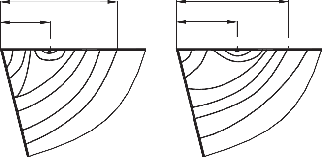
Fig. 4.26. Temperature field in the cutting wedge in turning. Work material – steel AISI 1045,
ν = 1 m/s, f = 0.3 mm/rev, d
w
= 2 mm, for two groups of tool materials: (a) carbide M20
(92% WC, 8% Co and (b) carbide P20 (77% WC, 15% TiC, 8% Co).
temperature fields for two basic groups of carbide tool materials experimentally as shown
in Figs. 4.26(a) and (b). The length of the plastic part l
c−p
of the tool–chip contact length
l
c
was measured for each tool and new tools were made with the restricted rake face
equal to l
c−p
. The experimental comparison of the plastic lowering of the cutting edge
of the tool with the natural and restricted contact lengths showed that this lowering is
much smaller for the latter tools. This is because much less heat is generated due to
the friction at the tool–chip interface so that a smaller thermal energy enters the tool.
By excluding this elastic part, the amount of the thermal energy entered into the cutting
tool substantially reduces the plastic lowering of the cutting edge. This explains the major
advantages of the tool with the restricted contact length known in practice.
It is also known [19,24] that significant intensification of high-temperature creep takes
place if the amplitude of cyclic load increases. As discussed in Chapter 1, the amplitude
of the cyclic cutting force grows when seizure occurs at the tool–chip interface (Fig. 1.25)
that results in the saw-toothed continuous fragmentary chip (Figs. 1.30–1.33). Therefore,
a noticeable increase in the plastic lowering of the cutting edge should be observed under
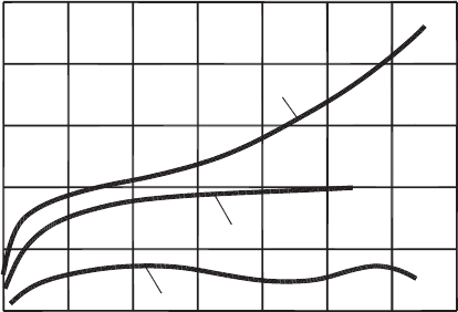
this condition. Figure 4.27 shows parameters characterizing the plastic lowering of the
cutting edge under the high-amplitude cutting force during the formation of this chip
type. Significant intensification of the plastic lowering of the cutting edge in this case
is readily observed if one compares Figs. 4.27 and 4.25(b). It explains the well-known
fact: tool life reduces significantly when the conditions at the tool–chip interface result
in the occurrence of the saw-toothed continuous fragmentary chip.
A comparison of the model of plastic lowering (shown in Figs. 4.23(a) and 4.25(a))
and the data shown in Fig. 4.27 shows that the model of plastic lowering is more com-
plicated than described so far. As shown, for example, h
α
first increases with increasing
Cutting Tool Wear, Tool Life and Cutting Tool Physical Resource 259
80
h
a
02
40
120
160
h
g
46810
h
f
h
a
, h
g
, h
f
(µm)
t (min)
Fig. 4.27. Intensification of the parameters of the plastic lowering of the cutting edge under the
condition of the increased cyclic loading (seizure). Turning of modified AK Steel (AISI Austenitic
Stainless Steel 305), ν = 1 m/s, f = 0.3 mm/rev, d
w
= 2 mm and carbide M20 (92% WC, 8% Co).
h
γ
and then, reaching a certain value, does not change any further. Talantov [24] sug-
gested that this is because the so-called wear land (of width h
f
in Fig. 4.23(a)) increases
not only due to the regular wear of the tool flank but also due to bulk deformation of the
cutting wedge.
To verify this suggestion, a special turning cutting test was carried out where the
actual width h
f −a
of the wear land was measured and the calculated wear land h
f −c
as determined through the radial tool wear h
r
and normal flank angle is,
h
f −c
= h
r
/tan α
n
. (4.28)
The following machining regime was used: workpiece material – AISI steel 1045, cutting
feed, f = 0.3mm/rev, depth of cut d
w
= 2 mm; cutting tool: tool materials – carbide
M20 (92% WC, 8% Co) and carbide P20 (77% WC, 15% TiC, 8% Co), tool geometry:
rake angle γ
n
= 0
◦
, flank angles α of the major and minor cutting edges α
n
= α
1n
= 10
◦
,
tool cutting edge angle of the major cutting edge κ = 45
◦
, tool cutting edge angle of the
minor cutting edge κ
1
= 15
◦
, tool nose radius r
n
= 0.25 mm.
The test results shown in Fig. 4.28 fully support the Talantov’s suggestion. As shown,
the actual width of the wear land h
f −a
is greater than the calculated (Eq. (4.28)) width of
this land, h
f −c
. This is because the actual width of the wear land increases not only due
to tool wear but also due to the creep of the cutting wedge. Analysis of the temperature
field shown in Fig. 4.26(a) and the contact conditions at the tool–chip interface (discussed
in Chapter 3) allows offering the following explanations to the described phenomena.
The cutting wedge is subjected to complicated plastic deformation in the cutting process.
A model of this deformation is shown in Fig. 4.29. A part of the cutting wedge (Zone 2 in
Fig. 4.29) deformed and moved toward the tool flank more intensively than its other parts
260 Tribology of Metal Cutting
0
4
812
h
f−a
, h
f−m
(mm)
t (min)
0.09
0.06
0.03
h
f−a
h
f−a
h
f−m
h
f−m
h
f−m
h
f−a
1045-M20
n=1.67m/s
1045-M20
n=1.33m/s
1045-P20
n=1.67m/s
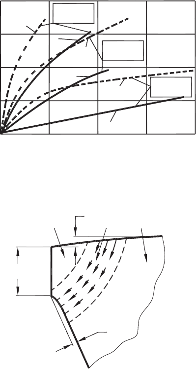
Fig. 4.28. Comparison of the actual (experimentally obtained), h
f −a
and calculated, h
f −c
widths
of the wear land.
h
f−a
h
g
h
a
O
K
Zone 1 Zone 2 Zone 3
Fig. 4.29. A model of the plastic lowering of the cutting edge.
shown as Zones 1 and 2. Such a behavior is explained by the temperature-deformation
stress relaxation where the temperature is a decisive factor. Starting with a certain tem-
perature, the intensity of stress relaxation increases significantly. The process of plastic
deformation where the intensity of stress growth is equal to that of stress relaxation due to
plastic deformation relates to creep. Analysis of the temperature fields of the cutting edge
(for example shown in Fig. 4.26) shows that there are some zones heated to significant
temperature over the whole volume from the rake face to the tool flank, as shown by the
corresponding isotherms. High-temperature creep takes place along these isotherms that
leads to the pushing out of some volumes of the tool material below the formed wear
Cutting Tool Wear, Tool Life and Cutting Tool Physical Resource 261
land on the tool flank. As tool wears, high-temperature creep of the material in Zone 2
becomes a continuous process as the temperatures in this zone increase proportionally
to tool wear.
At the same time, any motion of the tool material within Zone 1 is impossible as this
zone is loaded by the compressive stresses from the rake and flank contact surfaces.
Moreover, the temperatures in Zone 1 are lower than those in Zone 2. As a result, the
tool material in Zone 1 is not subjected to creep. As for Zone 3, high-temperature creep
does not occur here because of a number of reasons: lower temperatures, greater cross-
sectional areas and much lower contact stresses. As such, these temperatures in Zone 3
cause stress relaxation in this zone without its plastic deformation.
The description above allows us to conclude that some zones in the cutting wedge can be
subjected to plastic deformation under certain combination contact stresses/temperatures.
As such, this plastic deformation causes the growth of the wear land on the tool flank
without actual increase in tool wear. Therefore, the notion of the wear land on the tool
flank surface is conditional as this land forms not only due to tool wear but also due
to high-temperature creep (and thus plastic deformation) of the cutting wedge. This
conclusion is of particular importance for cutting tools with coatings.
For years Talantov [24] asked a simple question “How come a coating is able to reduce
tool wear of the tool flank for a long time period? It is known that the coating thick-
ness (the thickness of the coated layer) typically ranges from 3 to 10 µm. If the cutting
wedge would be ideally rigid having the flank angle α
n
= 10
◦
and the coating thick-
ness is 8 µm, then this coating should be gone when the width of the flank wear land
reaches 40 µm. Therefore, the coating under these conditions should be wiped out dur-
ing the first minute of machining. In practice, however, such a coating reduces the tool
wear rate during several dozens of minutes as the width of the flank wear land reaches
0.4–0.7 mm. The known explanations of this fact rely on the existence of “an overhung”
of the coating material over the tool flank although not one study can find this overhung
in reality [24].
Talantov proposed and proved a much simpler and real mechanism to explain the dis-
cussed fact. Figure 4.30 shows the cutting wedge after 10 min of cutting. As shown,
the coating exists over the whole flank wear land having a width of 0.4 mm. Therefore,
this is not just the wear land but rather it is the contact land formed due to the above-
described plastic lowering of the cutting wedge. To demonstrate the validity of such an
explanation, Talantov studied [24] the formation of the contact length in cutting tools
with TiN coating. Figure 4.31 shows the cutting wedge after 3 min of cutting. As shown,
the coating is still intact on the tool flank contact surface (except for some random chip-
ping) while there is no coating on the rake face in the zone, where certain volumes of
the tool material were pushed out towards the tool flank.
According to Talantov [24], the mechanism of high-temperature creep (the model shown
in Fig. 4.29) can be described as follows. In Zone 2 (Fig. 4.29), the fist phase of the
carbide tool material to deform is the cobalt matrix. Due to the action of the contact
stresses, this phase deforms along the direction shown by arrows in Fig. 4.29. This leads
to the destruction of the cobalt matrix which holds carbide particles as a frame. To prove
262 Tribology of Metal Cutting
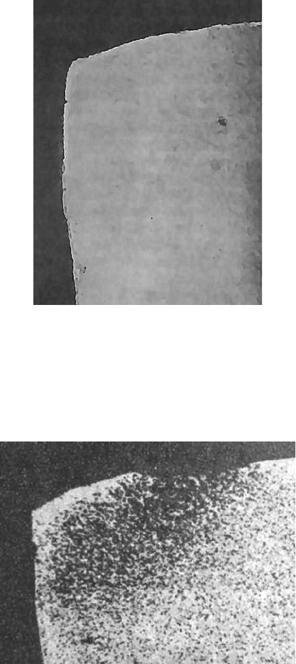
Fig. 4.30. Micrograph of the cutting wedge. Cutting conditions: work material – steel AISI 1070,
tool material – M10, coating – TiN, cutting speed ν = 90 m/min, feed f = 0.1 mm/rev, depth of
cut d
w
= 1.5 mm, cutting time τ = 10 min, magnification ×120.
Fig. 4.31. Micrograph of the cutting wedge. Cutting conditions: work material – steel AISI 1070,
tool material – P20, coating TiC, cutting speed ν = 100 m/min, feed f = 0.3 mm/rev, depth of
cut d
w
= 1.5 mm, cutting time τ = 3 min, magnification ×100.
Cutting Tool Wear, Tool Life and Cutting Tool Physical Resource 263
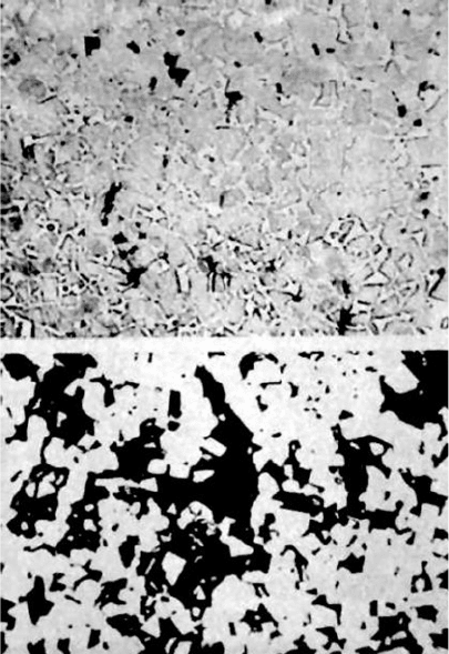
that this is the case, the worn tool wedge was mounted, polished and etched in a ferric
chloride solution in hydrochloric acid. The results of the described destruction can be
shown as a black region in Fig 4.31. As shown, the configuration of this black region
resembles the model shown in Fig. 4.29. The destruction of the cobalt matrix as a frame
can clearly be shown by comparing the initial carbide structure shown in Fig. 4.32(a) and
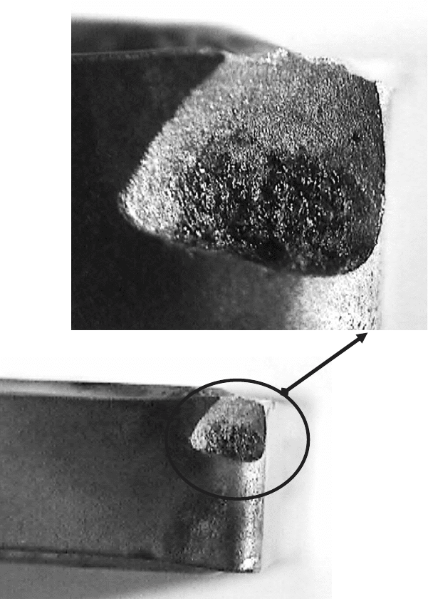
that after 7 min of machining shown in Fig. 4.32(b). This explains the fractography of
the broken cutting wedge shown in Fig. 4.33. As shown, the surface of fracture includes
two distinctive zones: one closer to the rake face represents the black region shown in
Fig 4.31 while the other resembles the fractography of normal brittle fracture of tool
carbide.
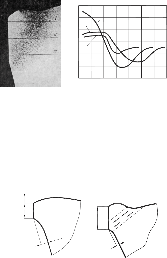
To evaluate the described destruction quantitatively, a microhardness scanning test was
carried out along the lines shown in Fig. 4.34(a). Figure 4.34(b) shows the distribution of
microhardness along these lines. As shown, the maximum microhardness was observed
in the regions of the cutting wedge adjacent to Zone 1 as this zone is always subjected
Fig. 4.32. Micrographs of the cutting wedge in Zone 2: (a) new tool and (b) tool after 7 min
of machining. Work material – tool steel HVG (1% C, 1% Cr, 1.5% W, 1% Mn), tool material
M30 (82% WC, 7% TaC, 3% TiC, 8% Co), cutting regime: cutting speed ν = 3.3 m/s, feed
f = 0.3 mm/rev, depth of cut d
w
= 1.5 mm, cutting time τ = 7 min, magnification ×2000.
264 Tribology of Metal Cutting
Fig. 4.33. Cutting wedge breakage as a result of plastic lowering. Fractography of breakage shows
two distinctive surfaces of fracture.
to high contact compressive stresses during machining [25,26]. The normal, for the tool
material used in the test, microhardness was observed in the regions of the cutting wedge
adjacent to Zone 3 as these regions were not subjected to high temperature and stresses
in cutting. The lowest microhardness readings are observed in the regions of the cutting
wedge adjacent to Zone 2 as a result of high temperature enhanced difussional stress
relaxation that led to the softening of the tool material in these regions.
Cutting Tool Wear, Tool Life and Cutting Tool Physical Resource 265
(a) (b)
I
0 0.2
13000
14000
15000
16000
17000
18000
HV (MPa)
0.4 0.6 0.8 1.0
Distance from
the flank (mm)
II
III
Fig. 4.34. Cutting wedge structure after 7 min of machining: (a) micrograph ×400, (b) micro-
hardness distribution along lines I, II and III. The cutting conditions are the same as in
Fig. 4.31.
Talantov suggested [24] that the plastic lowering of the cutting edge takes place dif-
ferently for different tool materials. He developed two distinctive modes shown in
Figs. 4.35 (a) and (b) for carbide tool. The first one shown in Fig. 4.35(a) is charac-
terized by the plastic lowering of the cutting and by bulging of the tool flank surface.
This mode is common for carbides having low thermal conductivity as carbides of ISO
P group (especially containing titanium carbides) when they are used for the machin-
ing of difficult-to-machine work materials of high strength and low thermoconductivity
(a)
h
a
h
a
(b)
h
f
h
f
h
g
Fig. 4.35. Two modes of plastic lowering of the cutting edge: (a) for low-thermoconductivity
carbides, ISO P group (b) for high-thermoconductivity carbides, ISO M group.
266 Tribology of Metal Cutting
i.e. when high temperature and high stress region in the cutting wedge are located close
to the cutting edge. The second mode shown in Fig. 4.35(b) is particularly for carbides of
higher thermoconductivity such as carbides of ISO M group, especially when the uncut
chip thickness (and thus the contact length) is great.
Tool breakage takes place when plastic lowering of the cutting edge reaches a certain
limit. This is because great interfacial stresses develop between plastically deformed due
to creep volumes of the tool material in Zone 2 and those in Zones 1 and 3. As a result
of these stresses, fracture takes place over the border between Zones 1 and 2 (more
common) or between 2 and 3 (less common). The former case is shown in Fig. 4.33.
Reading the described model, one may wonder if the plastic lowering of the cutting edge
is not a continuous phenomenon but rather occurs during a short time just before the
actual breakage of the cutting wedge. In other words, it can be assumed that the occur-
rence of the plastic lowering of the cutting edge results in a significant increase in the
cutting force that, in turn, leads to breakage. To prove that this is not the case, a special
cutting test was carried out where the components of the cutting force were recorded
using a high sensitive tool dynamometer as well as the level of micro vibrations of the
cutting tool using built-in accelerometers. The results of this test indicated that there is
no increase in the cutting force and tool vibration or any other spikes prior breakage of
the cutting wedge. Moreover, a good repitition of tool breakage life (12 min 30 s ±12
s
)
confirms that the plastic lowering of the cutting edge is a steady-state physical process.
4.8.3 Reduction
Plastic lowering of the cutting edge can be controlled to a large extent by the parameters
of the tool geometry. Among these parameters, the flank angle, the configuration of the
rake surface and the nose radius are of prime importance. Figure 4.36 shows profiles
of the flank surface for different flank angles. As shown, the smaller the flank angle,
smaller is the plastic lowering of the cutting edge. This leads to an important conclusion
known from machining practice: in machining of difficult-to-machine materials, the flank
angle should be chosen as small as is possible. The limitation is the possible interference
of the tool flank face and the machined (transient) surface. Therefore, an additional
module should be included in commercial programs for the verification tool path on
CNC machines that can verify the absence of the said interference.
Figure 4.37 shows the influence of the configuration of the rake surface. As shown, the
maximum cutting edge lowering occurs when “normal configuration” of the tool rake
face is used. A significant reduction in this plastic lowering is achieved when the rake
face is reinforced by a chamfer. It follows from Fig. 4.37 that the optimal geometry of
this chamfer exists for a given cutting condition. It should be pointed out that the width
of the discussed chamfer is much lower than the uncut chip thickness hence the tool is
not of the so-called negative geometry.
Figure 4.38 shows the influence of the tool nose radius. As shown, with the increase
in nose radius, plastic lowering decreases particularly in the region of the tool point.