ASME Section VIII div 2 2010. ASME Boiler and Pressure Vessel Code. Alternative Rules
Подождите немного. Документ загружается.


2010 SECTION VIII, DIVISION 2
5-89
5.D.3 Stress Indices for Laterals
5.D.3.1 The stress indices for laterals in cylindrical shells in Table 5.D.3 may be used when all of the
following conditions are satisfied:
a) The angle
θ
equals 45 deg; these indices may be used for angles of
θ
less than 45 degrees (see
Figure 5.D.3).
b) The nozzle is of circular cross section and has an axis that intersects the axis of the cylindrical vessel.
c) The design of the nozzle reinforcement is in accordance with the applicable rules of paragraph 4.5.
d) The following dimensional ratios are satisfied.
40.0
i
D
t
≤
(5.D.11)
0.5
ni
i
d
D
≤
(5.D.12)
3.0
ni
i
d
Dt
≤
(5.D.13)
e) The nominal pressure membrane stress to be used with the pressure indices is determined using the
following equations.
()
(12)
2
i
p
PD t
f
or Regions and
t
σ
+
=
(5.D.14)
()
(3)
2
ni p
p
p
Pd t
f
or Region
t
σ
+
=
(5.D.15)
5.D.3.2 Stress indices for laterals in cylindrical shells may be developed by stress analysis techniques
consistent with the elastic design analysis methods of Part 5, or obtained for other sources.
2010 SECTION VIII, DIVISION 2
5-90
5.D.4 Nomenclature
i
D inside vessel diameter.
ni
d inside nozzle diameter.
p
pressure.
1
r local nozzle radius, see Figure 5.D.2.
2
r local nozzle radius, see Figure 5.D.2.
3
r local nozzle radius, see Figure 5.D.2.
r
σ
stress component normal to the boundary of the section.
t
σ
stress component in the plane of the section under consideration and parallel to the boundary
of the section.
n
σ
stress component normal to the plane of the section (ordinarily the circumferential stress
around the hole in the shell.
t minimum wall thickness in the region under consideration, or the thickness of the vessel, as
applicable.
p
t thickness of perforated plate, or the thickness of the pipe portion of a nozzle, as applicable.
θ
angle between the axis of the nozzle and the normal to the vessel.
标准分享网 www.bzfxw.com 免费下载

2010 SECTION VIII, DIVISION 2
5-91
5.D.5 Tables
Table 5.D.1 – Stress Indices For Nozzles In Spherical Shells And Portions Of Formed Heads
Stress Inside Corner Outside Corner
n
σ
2.0 2.0
t
σ
0.2
−
2.0
r
σ
2t
R
−
0.0
σ
2.2 2.0
Table 5.D.2 – Stress Indices For Nozzles In Cylindrical Shells
Material Longitudinal Plane Transverse Plane
Inside Corner Outside Corner Inside Corner Outside Corner
n
σ
3.1 1.2 1.0 2.1
t
σ
0.2
−
1.0
0.2
−
2.6
r
σ
t
R
−
0.0
t
R
−
0.0
σ
3.3 1.2 1.2 2.6

2010 SECTION VIII, DIVISION 2
5-92
Table 5.D.3 – Stress Indices For Laterals
Load Stress Region 1 Region 2 Region 3
Inside (1) Outside (1) Inside Outside Inside Outside
Pressure
max
σ
5.5 0.8 3.3 0.7 1.0 1.0
S
5.75 0.8 3.5 0.75 1.2 1.1
In-Plane Branch
Moment,
B
M
max
σ
0.1 0.1 0.5 0.5 1.0 1.6
S
0.1 0.1 0.5 0.5 1.0 1.6
Vessel
Moments,
R
M
or
RT
M
max
σ
2.4 2.4 0.6 1.8 0.2 0.2
S
2.7 2.7 0.7 2.0 0.3 0.3
Out-Of-Plane
Branch
Moment,
BT
M
max
σ
0.13 NA 0.06 NA NA 2.5 (2)
S
0.22 NA 0.07 NA NA 2.5 (2)
Notes:
1. Inside/outside refers to inside corner (pressure side)/outside fillet and in the plane of symmetry as
shown in Figure 5.D.3
2. Maximum stress/stress intensity in Region 3 for transverse moment
BT
M
occurs 90
o
away from in-
plane moment.
标准分享网 www.bzfxw.com 免费下载
2010 SECTION VIII, DIVISION 2
5-93
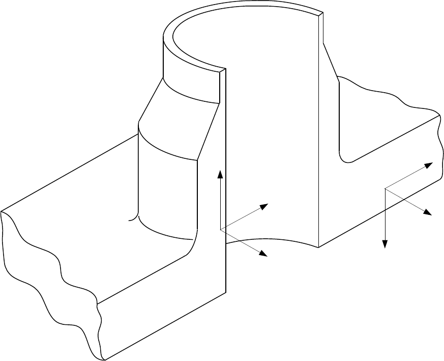
5.D.6 Figures
σ
t
σ
n
σ
r
σ
r
σ
n
σ
t
Figure 5.D.1
Direction of Stress Components
2010 SECTION VIII, DIVISION 2
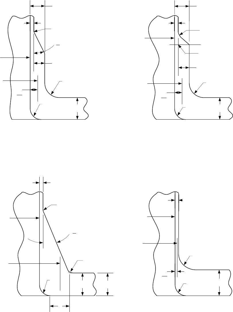
5-94
Shell Thickness
x
t
r
2
r
1
r
m
= r + 0.5t'
n
r
3
r
t
p
t'
n
= t
p
+ 0.667x
θ < 45°
t
r
1
r
m
r
3
r
t
n
θ < 45°
t
p
r
2
Offset
t
n
2
t
n
t
p
r
1
r
2
t
t
n
2
r
m
Offset
r
3
r
θ = 90°
t
r
1
r
2
t
n
2
r
m
r
t
n
, t
p
Figure 5.D.2
Nozzle Nomenclature and Dimensions
标准分享网 www.bzfxw.com 免费下载
2010 SECTION VIII, DIVISION 2
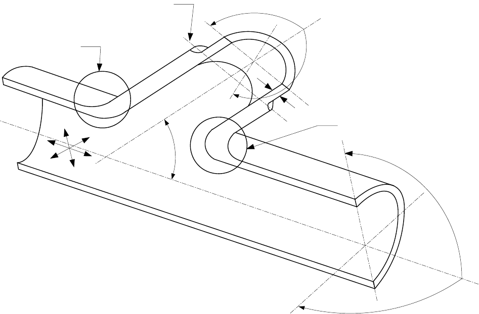
5-95
Region 1
M
R
M
RT
Region 3
A
A
t
P
M
BT
M
Β
Region 2
P
θ
Figure 5.D.3
Nomenclature and Loading for Laterals
2010 SECTION VIII, DIVISION 2
5-96
ANNEX 5.E
DESIGN METHODS FOR PERFORATED PLATES BASED ON
ELASTIC STRESS ANALYSIS
(NORMATIVE)
5.E.1 Overview
5.E.1.1 This paragraph contains a method of analysis for flat perforated plates subjected to applied loads or
loadings resulting from structural interaction with adjacent members. This method applies to perforated plates
that satisfy the following conditions:
a) The holes are in an equilateral triangular or square penetration pattern.
b) The holes are circular and the axis of the hole is perpendicular to the surface of the plate.
c) There are 19 or more holes.
d) The effective ligament efficiency satisfies the following criteria in paragraph 5.E.4.
5.E.1.2 Rolling or pressure expansion of tubes into a tubesheet will result in compression on the inside
diameter of the tubesheet perforation and the tube itself. Thermal transients that occur during operation may
result in thermal differential between the tube and the tubesheet resulting in a loss of the compression
obtained during fabrication. For tubes that are also welded, such thermal cycling can cause fatigue of the
weld joining the tube to the tubesheet. For tubes that are not welded, thermal cycling can cause the tube to
loose contact resulting in leakage. A transient thermal and stress analysis can determine the magnitude of
cyclic stress in the tube weld. For small ligaments, the pressure expansion of tubes can cause significant
ligament deformation and stresses.
5.E.2 Stress Analysis of the Equivalent Solid Plate
5.E.2.1 The analysis method for perforated plates presented in this paragraph is based on the concept of an
effective solid plate. In this method, the material properties of the actual perforated plate are replaced by
material properties of an effective solid plate that approximate the stiffness of the actual perforated plate. A
stress analysis is then performed where the effective solid plate is used in the model that is geometrically
similar to the perforated plate, and subject to the actual loading conditions. After completion of the stress
analysis, the values of the stresses in the actual perforated plate are obtained by applying stress multiplying
factors to the stress results computed for the effective solid plate.
5.E.2.2 An accurate model of the overall tubesheet behavior may be achieved by employing the concept of
an equivalent elastic material of anisotropic properties. For triangular penetration patterns the in-plane
behavior of the tubesheet is isotropic and the anisotropy of the equivalent material must only be considered
for stresses in the thickness direction. The tubesheet can be analyzed using an axisymmetric solid numerical
analysis with the effective elastic matrix
[]
E
to simulate the anisotropic behavior. For square penetration
patterns the equivalent material properties depend on the orientation of the loading with respect to the
symmetry axes of the pattern. The tubesheet can be analyzed using an axisymmetric solid numerical
analysis with the effective average elastic matrix
[]
E
for in-plane loading to simulate the anisotropic behavior.
When the tubesheet loading is not axisymmetric (e.g. channels with divider plates), a three-dimensional solid
numerical analysis may be required.
标准分享网 www.bzfxw.com 免费下载

2010 SECTION VIII, DIVISION 2
5-97
5.E.3 Stiffness Effects of the Tubes
5.E.3.1 The in-plane stiffening effect of the tubes in the perforations may be included in the analysis. The
extent to which the tubes stiffen the perforated plate depends on the materials, the manufacturing processes,
operating conditions, and degree of corrosion. This stiffening effect may be included in the calculations by
including part or all of the tube walls in the ligament efficiency used to obtain the effective elastic constants of
the plate. Such stiffening may either increase or decrease stresses in the plate itself and in the attached
shells.
5.E.3.2 Where applicable, the stiffening effect resulting from the staying action of the tubes should be
incorporated into the numerical analysis. For fixed-fixed type exchangers, the axial stiffness of the tubes shall
be included in the analysis. When including the tube stiffness, the difference in axial strain due to pressure
between the shell and tubes (Poisson’s effect) as well as differential thermal expansion between tubes and
shell should also be included in the numerical analysis.
5.E.4 Effective Material Properties for the Equivalent Solid Plate
5.E.4.1 The effective elastic constants of the perforated plate are determined as a function of the effective
ligament efficiency
*
μ
that is computed in accordance with paragraph 4.18.6.4.
5.E.4.2 If the hole pattern is irregular or has isolated thin ligaments in a uniform hole pattern, the calculated
elastic constants shall represent the average ligament size over the entire modeled plate in order to capture
the global response. The stress multipliers used for the fatigue assessment of paragraph 5.E.7.2 shall be
computed considering the appropriate ligament efficiency for the location of interest.
5.E.4.3 The effective elastic constants of the perforated plate material are determined based on the hole
pattern and thickness of the plate. Either one of the following two options may be used in the analysis.
a) Option A – The effective elastic constants are provided below. Elastic constants are provided for the
effective elastic modulus and effective Poisson’s ratio. A value for the effective shear modulus, which is
required in the analysis method in this annex, is not provided. The effective shear modulus shall be
evaluated using Option B.
1) Triangular Hole Pattern – The effective elastic modulus and effective Poison’s ratio are provided in
Tables 5.E.1 and 5.E.2, respectively.
2) Square Hole Pattern – The effective elastic modulus and effective Poisson’s ratio are provided in
Tables 5.E.3 and 5.E.4, respectively. The effective elastic modulus and Poisson’s ratio represent
an equivalent isotropic value considering the values of the pitch and diagonal properties.
3) Range of Applicability – The range of applicability in terms of the effective tube pitch is
*
0.1 1.0
μ
≤≤. The effective elastic constants
*
E and
*
ν
can be used for in-plane loading and
bending loading of all values of
hp.
4) The value of the in-plane shear modulus is given by Equation (5.E.1). The value of the out-of-plane
shear modulus
*
z
G shall be computed using Option B.
()
*
*
*
21
E
G
υ
=
+
(5.E.1)

2010 SECTION VIII, DIVISION 2
5-98
b) Option B – The effective elastic constants for plane stress and generalized plane strain are provided
below.
1) Triangular Hole Pattern – The effective elastic modulus and effective Poison’s ratio are provided in
Table 5.E.5
2) Square Hole Pattern – The effective elastic modulus and effective Poisson’s ratio for the pitch and
diagonal directions are provided in Tables 5.E.6 and 5.E.7, respectively.
3) Effects Of Poisson’s Ratio – The effective material constants in Tables 5.E.5, 5.E.6, and 5.E.7 are
based on a Poisson’s ratio of
0.3
ν
= . The material constants can be determined for other values
of Poisson’s ratio using the following procedure.
i) For a given value of
*
μ
, determine
*
E and
*
ν
using the equations in Tables 5.E.5, 5.E.6, and
5.E.7, as applicable. These values correspond to
0.3
ν
=
.
ii) Determine
0
F using the following equation:
*
0
E
F
E
= (5.E.2)
iii) Determine
1
F using the following equation:
*
10
0.3FF
ν
=− (5.E.3)
iv) The value of
*
ν
for any value of the Poisson’s ratio,
ν
, is:
*
10
() FF
ν
νν
=+
(5.E.4)
v) With the value of
*
()
ν
ν
determined above, the effective elastic modulus and shear modulus
can be determined for any value of the Poisson’s ratio by using the equations in Tables 5.E.5,
5.E.6, and 5.E.7, as applicable.
4) Range of Applicability – The range of applicability in terms of the effective tube pitch is
*
0.1 1.0
μ
≤≤. The range of applicability in terms of hp is:
i) The effective elastic constants
*
E and
*
ν
can be used for in-plane loading and bending
loading when
2.0hp≥ .
ii) The effective elastic constants
*
E and
*
ν
can be used for in-plane loading when 2.0hp
<
.
The effective constants in Option A can be used for bending loading when
2.0hp< .
iii) The effective elastic constants
*
G ,
*
p
G ,
*
d
G , and
*
z
G can be used for in-plane loading and
bending loading for all values of
hp.
iv) The effective elastic constants for plane stress shall be used when
2hp< , and the effective
elastic constants for generalized plane strain shall be used when
2hp≥ .
c) Option C – The effective elastic constants for the geometry being evaluated can be derived by stress
analysis. In this case, the tube layout geometry is modeled and loads are applied to introduce normal
and shear stresses. The effective elastic constants can be derived from the stress and strain results
from the stress analysis.
标准分享网 www.bzfxw.com 免费下载