ASME Section VIII div 2 2010. ASME Boiler and Pressure Vessel Code. Alternative Rules
Подождите немного. Документ загружается.

2010 SECTION VIII, DIVISION 2
5-69
C
L
A
A
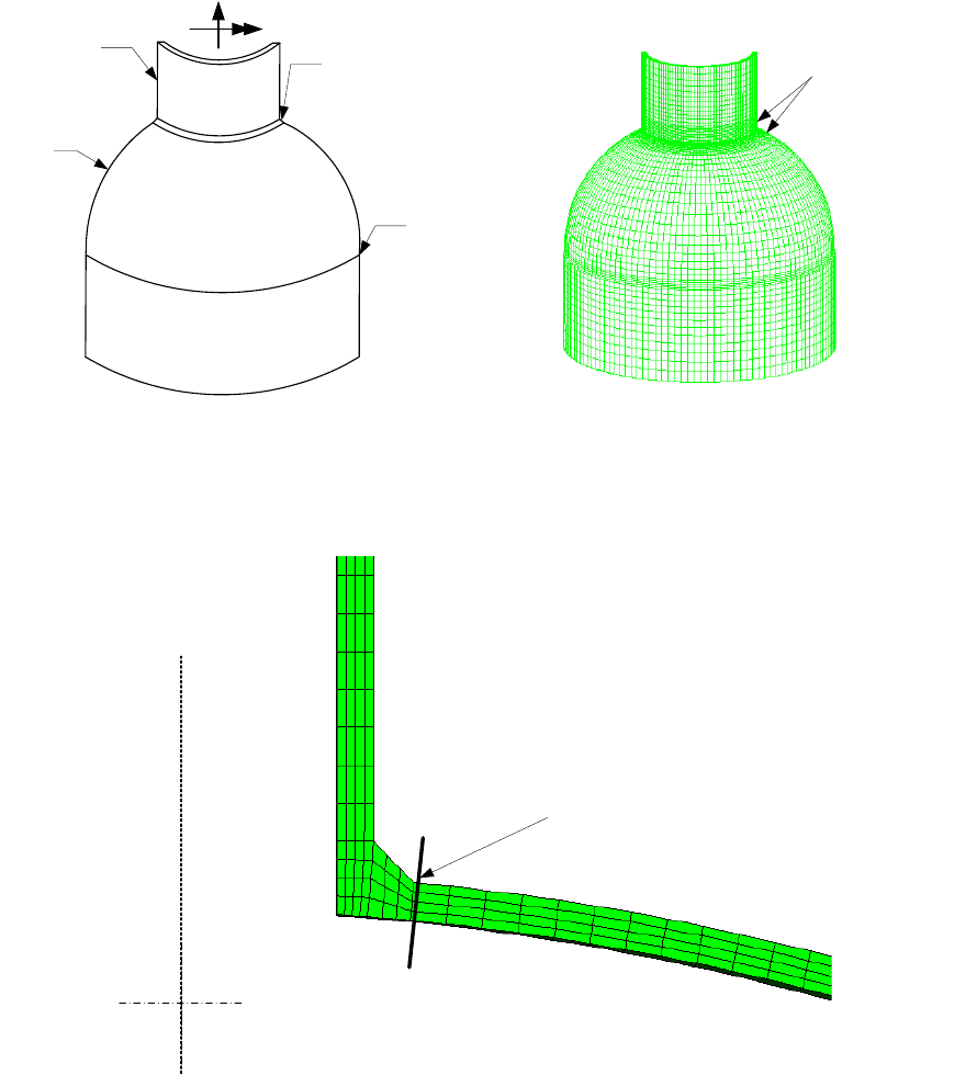
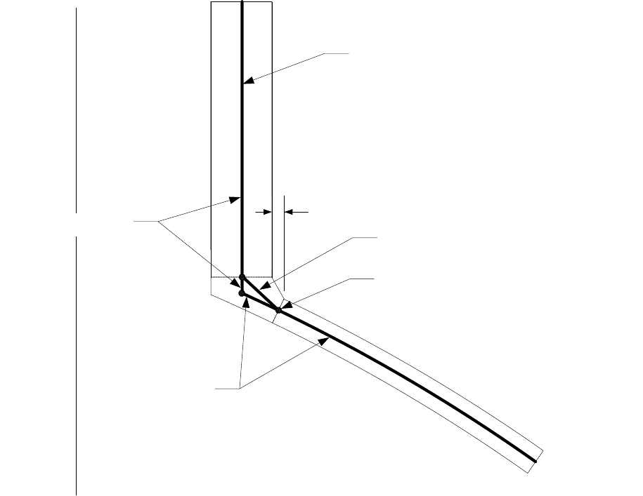
Stress Evaluation Line
Weld Toe
Elements should
be orthogonal to
Weld Joint
F
M
nozzle
corner joint with fillet
weld
head
butt joint
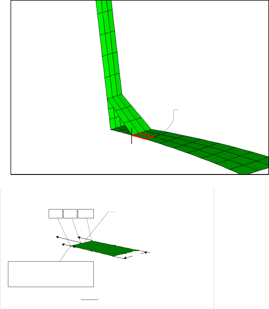
(a) Component Geometry (b) Finite Element Mesh
(c) Section A-A Stress Classification LIne
Figure 5.A.5
Continuum Finite Element Model Stress Classification Line for the Structural Stress Method
2010 SECTION VIII, DIVISION 2
5-70
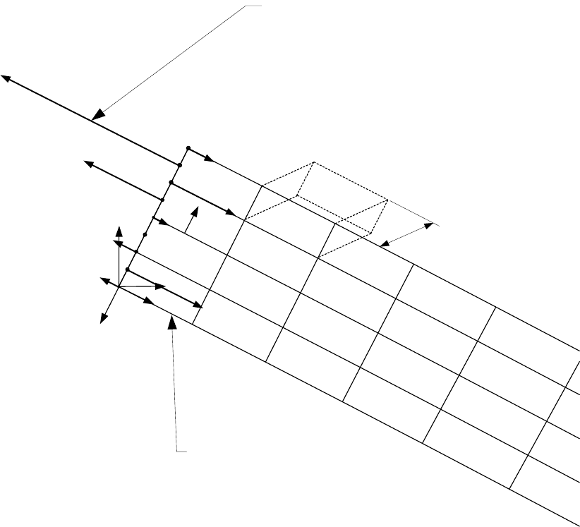
Elements Orthogonal to Stress
Evaluation Line
y
L
x
L
y
g
x
g
Internal Nodal Forces (NF
j
)
Transformed to local coordinate system
s
j
(Element Width for 3D
continuum)
w
A
A
Figure 5.A.6
Computation of Membrane and Bending Equivalent Stresses by the Structural Stress Method Using
Nodal Force Results from a Finite Element Model with Continuum Elements
标准分享网 www.bzfxw.com 免费下载
2010 SECTION VIII, DIVISION 2
5-71
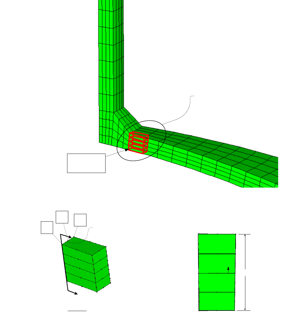
Element Nodal
Internal Forces
See Detail A
i=1
i=2
i=3
EL1
EL2
EL3
EL4
i=1,2,3 following
weld toe
A
A
Detail A
i=3 i=2 i=1
EL1
EL2
EL3
EL4
S
j
t
Section A-A
Figure 5.A.7
Processing Nodal Force Results with the Structural Stress Method Using the Results from a Finite
Element Model with Three Dimensional Second Order Continuum Elements
2010 SECTION VIII, DIVISION 2
5-72
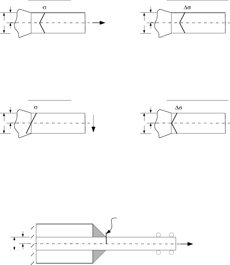
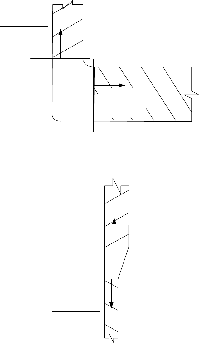
t
t/2
t
t/2
Structural Stress Structural Stress Range
t
t/2
t
t/2
Structural Stress Structural Stress Range
Tension
Bending
(a) Symmetric Structural Stress State (symmetric joint and symmetric loading)
(b) Anti-symmetric Structural Stress State (symmetric joint and anti-symmetric loading)
s
s
s
s
t
(c) Example of Symmetric Joint (double plate lap fillet weld)
F
F
F
t/2
SCL at fillet weld toe (extends
across one-half of the thickness)
Figure 5.A.8
Processing Structural Stress Method Results for a Symmetric Structural Stress Range
标准分享网 www.bzfxw.com 免费下载
2010 SECTION VIII, DIVISION 2
5-73
C
L
Head Thickness
Nozzle Thickness
Weld Leg
Weld Throat Thickness (see Note 1)
Shell Model at Mean
Radius of Nozzle and Shell
Stress Evaluation Point
Note 1: The thickness and material properties of the shell element used to model the fillet weld should be
established based on producing an equivalent stiffness of the actual fillet weld.
Figure 5.A.9
Computation of Membrane and Bending Equivalent Stresses by the Structural Stress Method Using
the Results from a Finite Element Model with Shell Elements
2010 SECTION VIII, DIVISION 2
5-74
A
A
Y
L
EL1
i=1 i=2 i=3
w
NF1
NF2
NF3
NF1-NF3 Transformed to Y
L
direction
weld toe
See Detail A
Detail A
Figure 5.A.10
Processing Nodal Force Results with the Structural Stress Method Using the Results from a Finite
Element Model With Three Dimensional Second Order Shell Elements
标准分享网 www.bzfxw.com 免费下载
2010 SECTION VIII, DIVISION 2
5-75
Nozzle Neck
SCL
Shell SCL
Element set
processed for
shell SCL
Element set
processed for
nozzle SCL
Thin
Plate
SCL
Thick
Plate
SCL
Element set
processed for
thick plate SCL
Element set
processed for
thin plate SCL
Figure 5.A.11
Element Sets for Processing Finite Element Nodal Stress Results with the Structural Stress Method
Based on Stress Integration
2010 SECTION VIII, DIVISION 2
5-76
ANNEX 5.B
HISTOGRAM DEVELOPMENT AND CYCLE COUNTING FOR
FATIGUE ANALYSIS
(INFORMATIVE)
5.B.1 General
This annex contains cycle counting procedures required to perform a fatigue assessment for irregular stress
or strain versus time histories. These procedures are used to break the loading history down into individual
cycles that can be evaluated using the fatigue assessment rules of Part 5. Two cycle counting methods are
presented in this Appendix. An alternative cycle counting method may be used if agreed to by the Owner-
User.
5.B.2 Definitions
The definitions used in this Annex are shown below.
a) Event – The Users’ Design Specification may include one or more events that produce fatigue damage.
Each event consists of loading components specified at a number of time points over a time period and
is repeated a specified number of times. For example, an event may be the startup, shutdown, upset
condition, or any other cyclic action. The sequence of multiple events may be specified or random.
b) Cycle – A cycle is a relationship between stress and strain that is established by the specified loading at
a location in a vessel or component. More than one stress-strain cycle may be produced at a location,
either within an event or in transition between two events, and the accumulated fatigue damage of the
stress-strain cycles determines the adequacy for the specified operation at that location. This
determination shall be made with respect to the stabilized stress-strain cycle.
c) Proportional Loading – During constant amplitude loading, as the magnitudes of the applied stresses
vary with time, the size of Mohr’s circle of stress also varies with time. In some cases, even though the
size of Mohr’s circle varies during cyclic loading, if the orientation of the principal axes remains fixed, the
loading is called proportional. An example of proportional loading is a shaft subjected to in-phase torsion
and bending, where the ratio of axial and torsional stress remains constant during cycling.
d) Non-Proportional Loading – If the orientation of the principal axes are not fixed, but change orientation
during cyclic loading, the loading is called non-proportional. An example of non-proportional loading is a
shaft subjected to out-of-phase torsion and bending, where the ratio of axial and torsional stress varies
continuously during cycling.
e) Peak – The point at which the first derivative of the loading or stress histogram changes from positive to
negative.
f) Valley – The point at which the first derivative of the loading or stress histogram changes from negative
to positive.
5.B.3 Histogram Development
5.B.3.1 The loading histogram should be determined based on the specified loadings provided in the Users’
Design Specification. The loading histogram should include all significant operating loads and events that are
applied to the component. The following should be considered in developing the loading histogram.
a) The number of repetitions of each event during the operation life.
标准分享网 www.bzfxw.com 免费下载
2010 SECTION VIII, DIVISION 2
5-77
b) The sequence of events during the operation life, if applicable.
c) Applicable loadings such as pressure, temperature, supplemental loads such as weight, support
displacements, and nozzle reaction loadings.
d) The relationship between the applied loadings during the time history.
5.B.4 Cycle Counting Using the Rainflow Method
5.B.4.1 The Rainflow Cycle Counting Method (ASTM Standard No. E1049) is recommended to determine the
time points representing individual cycles for the case of situations where the variation in time of loading,
stress, or strain can be represented by a single parameter. This cycle counting method is not applicable for
non-proportional loading. Cycles counted with the Rainflow Method correspond to closed stress-strain
hysteresis loops, with each loop representing a cycle.
5.B.4.2 Recommended Procedure
a) STEP 1 – Determine the sequence of peaks and valleys in the loading histogram. If multiple loadings
are applied, it may be necessary to determine the sequence of peaks and valleys using a stress
histogram. If the sequence of events is unknown, the worst case sequence should be chosen.
b) STEP 2 – Re-order the loading histogram to start and end at either the highest peak or lowest valley, so
that only full cycles are counted. Determine the sequence of peaks and valleys in the loading history. Let
X
denote the range under consideration, and let Y denote the previous range adjacent to
X
.
c) STEP 3 – Read the next peak or valley. If out of data, go to STEP 8.
d) STEP 4 – If there are less than 3 points, go to STEP 3; If not, form ranges X and Y using the three most
recent peaks and valleys that have not been discarded.
e) STEP 5 – Compare the absolute values of ranges X and Y.
1) If
X
Y< go to STEP 3
2) If
X
Y≥
go to STEP 6
f) STEP 6 – Count range
Y as one cycle; discard the peak and valley of Y . Record the time points and
loadings or component stresses, as applicable, at the starting and ending time points of the cycle.
g) STEP 7 – Return to STEP 4 and repeat STEPs 4 to 6 until no more time points with stress reversals
remain.
h) STEP 8 – Using the data recorded for the counted cycles perform fatigue assessment in accordance with
Part 5.
5.B.5 Cycle Counting Using Max-Min Cycle Counting Method
5.B.5.1 Overview
The Max-Min Cycle Counting Method is recommended to determine the time points representing individual
cycles for the case of non-proportional loading. The cycle counting is performed by first constructing the
largest possible cycle, using the highest peak and lowest valley, followed by the second largest cycle, etc.,
until all peak counts are used.
5.B.5.2 Recommended Procedure
a) STEP 1 – Determine the sequence of peaks and valleys in the loading history. If some events are
known to follow each other, group them together but otherwise arrange the random events in any order.

2010 SECTION VIII, DIVISION 2
5-78
b) STEP 2 – Calculate the elastic stress components
ij
σ
produced by the applied loading at every point in
time during each event at a selected location of a vessel. All stress components must be referred to the
same global coordinate system. The stress analysis must include peak stresses at local discontinuities.
c) STEP 3 – Scan the interior points of each event and delete the time points at which none of the stress
components indicate reversals (peaks or valleys).
d) STEP 4 – Using the stress histogram from STEP 2, determine the time point with the highest peak or
lowest valley. Designate the time point as
m
t , and the stress components as
m
ij
σ
.
e) STEP 5 – If time point
m
t is a peak in the stress histogram, determine the component stress range
between time point
m
t and the next valley in the stress histogram. If time point
m
t is a valley, determine
the component stress range between time point
m
t
and the next peak. Designate the next time point
as
n
t , and the stress components as
n
ij
σ
. Calculate the stress component ranges and the von Mises
equivalent stress range between time points
m
t
and
n
t
.
mn m n
ij ij ij
σ
σσ
Δ= −
(5.B.1)
()()
()( )
0.5
22
11 22 22 33
2
222
33 11 12 23 31
1
2
6
mn mn mn mn
mn
range
mn mn mn mn mn
S
σσ σσ
σσ σσσ
⎡⎤
Δ−Δ +Δ−Δ +
⎢⎥
Δ=
⎢⎥
Δ−Δ + Δ+Δ+Δ
⎢⎥
⎣⎦
(5.B.2)
f) STEP 6 – Repeat STEP 5, for the current time point,
m
t
and the time point of the next peak or valley in
the sequence of the stress histogram. Repeat this process for every remaining time point in the stress
histogram.
g) STEP 7 – Determine the maximum von Mises equivalent stress range obtained in STEP 5 and record
the time points
m
t and
n
t that define the start and end points of the
th
k cycle.
h) STEP 8 – Determine the event or events to which the time points
m
t and
n
t belong and record their
specified number of repetitions as
m
N
and
n
N
, respectively.
i) STEP 9 – Determine the number of repetitions of the
th
k cycle.
1) If
mn
NN< : Delete the time point
m
t from those considered in STEP 4, and reduce the number of
repetitions at time point
n
t from
n
N to ()
nm
NN− .
2) If
mn
NN>
: Delete the time point
n
t
from those considered in STEP 4, and reduce the number of
repetitions at time point
m
t from
m
N to ()
mn
NN− .
3) If
mn
NN= : Delete both time points
m
t and
n
t from those considered in STEP 4.
j) STEP 10 – Return to STEP 4 and repeat STEPs 4 to 10 until no more time points with stress reversals
remain.
k) STEP 11 – Using the data recorded for the counted cycles, perform fatigue assessment in accordance
with Part 5. Note that an elastic-plastic fatigue assessment (see Part 5, paragraph 5.5.4) may be applied
if
mn
range
SΔ exceeds the yield point of the cyclic stress range-strain range curve of the material.
标准分享网 www.bzfxw.com 免费下载