ASME Section VIII div 2 2010. ASME Boiler and Pressure Vessel Code. Alternative Rules
Подождите немного. Документ загружается.

2010 SECTION VIII, DIVISION 2
5-49
Table 5.7 – Uniaxial Strain Limit for use in Multiaxial Strain Limit Criterion
Material
Maximum
Temperature
Lu
ε
Uniaxial Strain Limit (1), (2), (3)
s
l
α
2
m
Elongation
Specified
Reduction of
Area Specified
Ferritic Steel
480°C (900°F)
(
)
0.60 1.00
R
−
2ln1
100
E
⎡
⎤
⋅+
⎢
⎥
⎣
⎦
100
ln
100
R
A
⎡⎤
⎢⎥
−
⎣⎦
2.2
Stainless Steel
and Nickel
Base Alloys
480°C (900°F)
(
)
0.75 1.00
R
−
3ln1
100
E
⎡
⎤
⋅+
⎢
⎥
⎣
⎦
100
ln
100
R
A
⎡⎤
⎢⎥
−
⎣⎦
0.6
Duplex
Stainless Steel
480°C (900°F)
(
)
0.70 0.95
R
−
2ln1
100
E
⎡
⎤
⋅+
⎢
⎥
⎣
⎦
100
ln
100
R
A
⎡⎤
⎢⎥
−
⎣⎦
2.2
Super Alloys
(4)
480°C (900°F)
(
)
1.90 0.93
R
−
ln 1
100
E
⎡
⎤
+
⎢
⎥
⎣
⎦
100
ln
100
R
A
⎡⎤
⎢⎥
−
⎣⎦
2.2
Aluminum
120°C (250°F)
(
)
0.52 0.98
R
−
1.3 ln 1
100
E
⎡
⎤
⋅+
⎢
⎥
⎣
⎦
100
ln
100
R
A
⎡⎤
⎢⎥
−
⎣⎦
2.2
Copper
65°C (150°F)
(
)
0.50 1.00
R
−
2ln1
100
E
⎡
⎤
⋅+
⎢
⎥
⎣
⎦
100
ln
100
R
A
⎡⎤
⎢⎥
−
⎣⎦
2.2
Titanium and
Zirconium
260°C (500°F)
(
)
0.50 0.98
R
−
1.3 ln 1
100
E
⎡
⎤
⋅+
⎢
⎥
⎣
⎦
100
ln
100
R
A
⎡⎤
⎢⎥
−
⎣⎦
2.2
Notes:
1. If the elongation and reduction in area are not specified, then
2Lu
m
ε
=
. If the elongation or
reduction in area is specified, then
Lu
ε
is the maximum number computed from columns 3, 4 or 5,
as applicable.
2.
R
is the ratio of the minimum specified yield strength divided by the minimum specified ultimate
tensile strength.
3.
E
is the % elongation and
R
A is the % reduction in area determined from the applicable material
specification.
4. Precipitation hardening austenitic alloys
2010 SECTION VIII, DIVISION 2
5-50
Table 5.8 – Temperature Factors For Fatigue Screening Criteria
Metal temperature Differential
Temperature Factor For Fatigue Screening
Criteria
°C °F
28 or less 50 or less 0
29 to 56 51 to 100 1
57 to 83 101 to 150 2
84 to 139 151 to 250 4
140 to 194 251 to 350 8
195 to 250 351 to 450 12
Greater than 250 Greater than 450 20
Notes:
1. If the weld metal temperature differential is unknown or cannot be established, a value of 20 shall be
used.
2. As an example illustrating the use of this table, consider a component subject to metal temperature
differentials for the following number of thermal cycles.
Temperature Differential Temperature Factor Based On
Temperature Differential
Number Of Thermal
Cycles
28 °C (50 °F)
0 1000
50 °C (90 °F)
1 250
222 °C (400 °F)
12 5
The effective number of thermal cycles due to changes in metal temperature is:
() ()
(
)
1000 0 250 1 5 12 310
TE
Ncycles
Δ
=++=
标准分享网 www.bzfxw.com 免费下载

2010 SECTION VIII, DIVISION 2
5-51
Table 5.9 – Fatigue Screening Criteria For Method A
Description
Integral
Construction
Attachments and nozzles in the knuckle
region of formed heads
350
FP PO TE T
NNNN
α
ΔΔ ΔΔ
+
++≤
All other components
1000
FP PO TE T
NNNN
α
ΔΔ ΔΔ
+
++≤
Non-integral
construction
Attachments and nozzles in the knuckle
region of formed heads
60
FP PO TE T
NNNN
α
ΔΔ ΔΔ
+
++≤
All other components
400
FP PO TE T
NNNN
α
ΔΔ ΔΔ
+
++≤
Table 5.10 – Fatigue Screening Criteria Factors For Method B
Description
1
C
2
C
Integral
Construction
Attachments and nozzles in the knuckle
region of formed heads
4
2.7
All other components
3
2
Non-integral
construction
Attachments and nozzles in the knuckle
region of formed heads
5.3 3.6
All other components
4
2.7
Table 5.11 – Weld Surface Fatigue-Strength-Reduction Factors
Weld
Condition
Surface
Condition
Quality Levels (see Table 5.12)
1 2 3 4 5 6 7
Full penetration
Machined 1.0 1.5 1.5 2.0 2.5 3.0 4.0
As-welded 1.2 1.6 1.7 2.0 2.5 3.0 4.0
Partial
Penetration
Final Surface
Machined
NA 1.5 1.5 2.0 2.5 3.0 4.0
Final Surface
As-welded
NA 1.6 1.7 2.0 2.5 3.0 4.0
Root NA NA NA NA NA NA 4.0
Fillet
Toe machined NA NA 1.5 NA 2.5 3.0 4.0
Toe as-welded NA NA 1.7 NA 2.5 3.0 4.0
Root NA NA NA NA NA NA 4.0

2010 SECTION VIII, DIVISION 2
5-52
Table 5.12 – Weld Surface Fatigue-Strength-Reduction Factors
Fatigue-Strength-Reduction
Factor
Quality
Level
Definition
1.0 1
Machined or ground weld that receives a full volumetric examination,
and a surface that receives MT/PT examination and a VT examination.
1.2 1
As-welded weld that receives a full volumetric examination, and a
surface that receives MT/PT and VT examination
1.5 2
Machined or ground weld that receives a partial volumetric
examination, and a surface that receives MT/PT examination and VT
examination
1.6 2
As-welded weld that receives a partial volumetric examination, and a
surface that receives MT/PT and VT examination
1.5 3
Machined or ground weld surface that receives MT/PT examination
and a VT examination (visual), but the weld receives no volumetric
examination inspection
1.7 3
As-welded or ground weld surface that receives MT/PT examination
and a VT examination (visual), but the weld receives no volumetric
examination inspection
2.0 4
Weld has received a partial or full volumetric examination, and the
surface has received VT examination, but no MT/PT examination
2.5 5
VT examination only of the surface; no volumetric examination nor
MT/PT examination.
3.0 6 Volumetric examination only
4.0 7 Weld backsides that are non-definable and/or receive no examination.
Notes:
1. Volumetric examination is RT or UT in accordance with Part 7.
2. MT/PT examination is magnetic particle or liquid penetrant examination in accordance with Part 7
3. VT examination is visual examination in accordance with Part 7.
4. See WRC Bulletin 432 for further information.
标准分享网 www.bzfxw.com 免费下载
2010 SECTION VIII, DIVISION 2
5-53
Table 5.13 – Fatigue Penalty Factors For Fatigue Analysis
Material
e
K (1)
max
T (2)
m n
(
o
C) (
o
F)
Low alloy steel 2.0 0.2 371 700
Martensitic stainless steel 2.0 0.2 371 700
Carbon steel 3.0 0.2 371 700
Austenitic stainless steel 1.7 0.3 427 800
Nickel-chromium-iron 1.7 0.3 427 800
Nickel-copper 1.7 0.3 427 800
Notes:
1. Fatigue penalty factor
2. The fatigue penalty factor should only be used if all of the following are satisfied:
• The component is not subject to thermal ratcheting, and
• The maximum temperature in the cycle is within the value in the table for the material.
2010 SECTION VIII, DIVISION 2
5-54
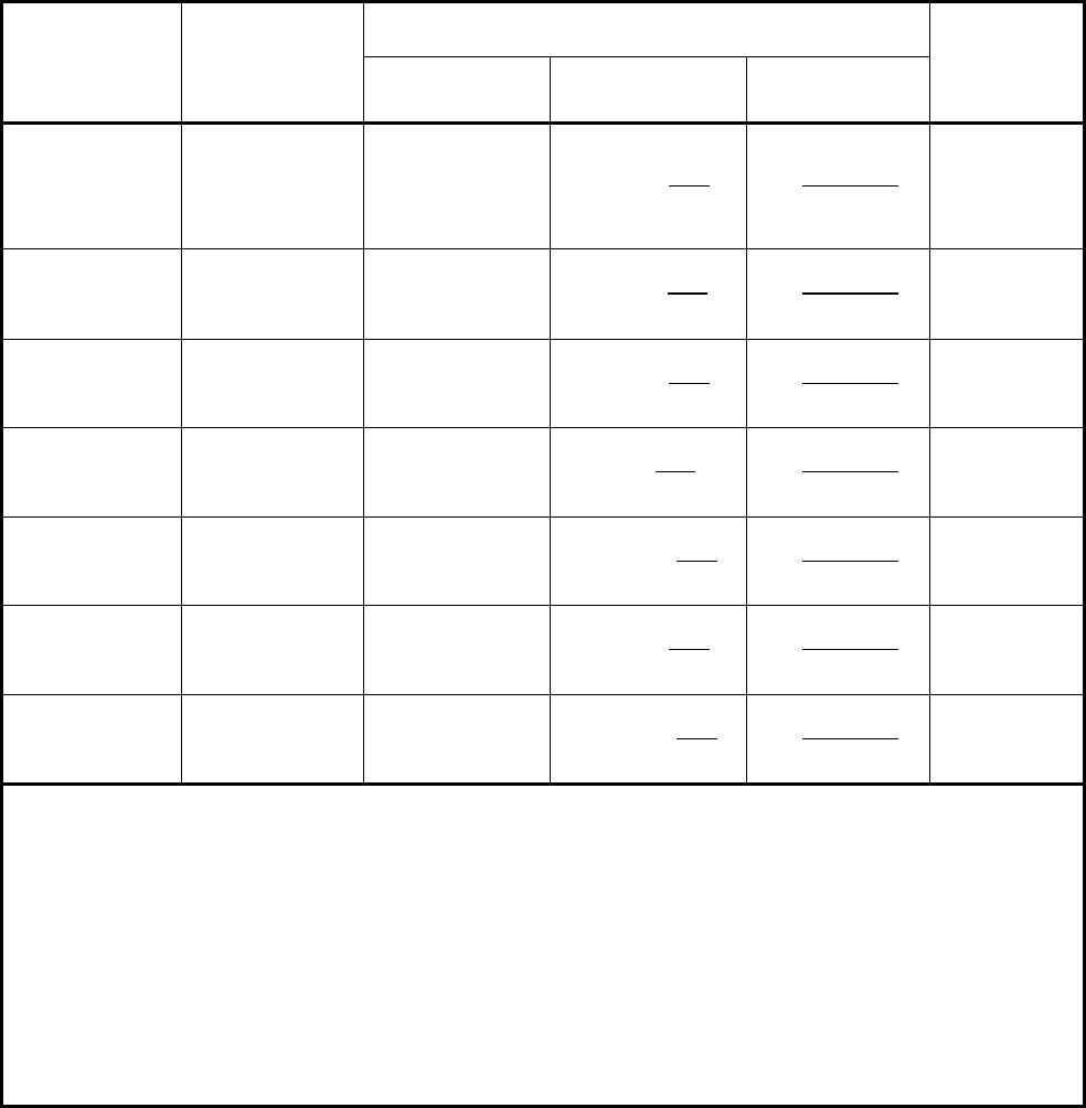
5.15 Figures
P
m
S
P
L
1.5S
P
L
+ P
b
P
L
+ P
b
+ Q
P
L
+ P
b
+ Q + F
S
PS
S
a
Use design loads
Use operating loads
Primary
General
Membrane
Local
Membrane
Bending
Secondary
Membrane
plus Bending
Peak
Stress
Category
Descrip-
tion (For
examples,
see Table
5.2)
Average primary
stress across
solid section.
Excludes dis-
continuities and
concentrations.
Produced only
by mechanical
loads.
Average stress
across any solid
section.
Considers dis-
continuities but
not concentra-
tions. Produced
only by mech-
anical loads.
Component of
primary stress
proportional to
distance from
centroid of solid
section.
Excludes dis-
continuities and
concentrations.
Produced only
by mechanical
loads.
Self-equilibrating
stress necessary
to satisfy contin-
uity of structure.
Occurs at struc-
tural discontinui-
ties. Can be
caused by
mechanical load
or by differential
thermal
expansion.
Excludes local
stress
concentrations.
1. Increment
added to
primary or
secondary
stress by a
concentration
(notch).
2. Certain ther-
mal stresses
which may
cause fatigue
but not distor-
tion of vessel
shape.
Symbol P
m
P
L
P
b
QF
1.5S
Figure 5.1
Stress Categories and Limits of Equivalent Stress
标准分享网 www.bzfxw.com 免费下载
2010 SECTION VIII, DIVISION 2
5-55
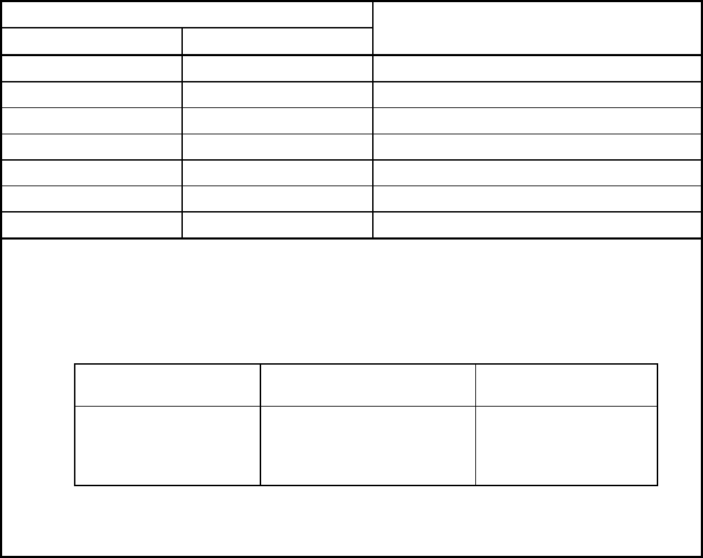
C
L
t
w
M
1
F
1
Girth Weld
External Loads Acting
Circumferentially Around
Shell
Figure 5.2
Example of Girth Weld Used to Tie Layers for Solid Wall Equivalence
t
w
Conical Section
C
L
Figure 5.3
Example of Circumferential Butt Weld Attachment Between Layered Sections in Zone of Discontinuity
2010 SECTION VIII, DIVISION 2
5-56
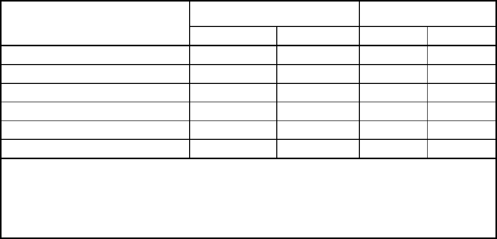
t
H
C
L
Circle Weld
w
F
1
Q
1
External Loads Acting
Around Circle of
Spherical Shell
M
1
Figure 5.4
An Example of Circle Weld Used to Tie Layers for Solid Wall Equivalence
标准分享网 www.bzfxw.com 免费下载
2010 SECTION VIII, DIVISION 2
5-57
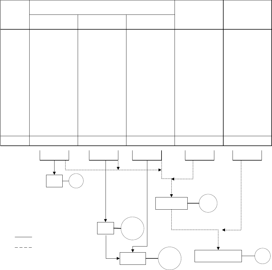
ANNEX 5.A
LINEARIZATION OF STRESS RESULTS FOR STRESS
CLASSIFICATION
(INFORMATIVE)
5.A.1 Scope
This Annex provides recommendations for post-processing of the results from an elastic finite element stress
analysis for comparison to the limits in paragraph 5.2.2.
5.A.2 General
a) In the finite element method, when continuum elements are used in an analysis, the total stress
distribution is obtained. Therefore, to produce membrane and bending stresses, the total stress
distribution shall be linearized on a stress component basis and used to calculate the equivalent
stresses. If shell elements (shell theory) are used, then the membrane and bending stresses shall be
obtained directly from shell stress resultants.
b) Membrane and bending stresses are developed on cross sections through the thickness of a component.
These sections are called stress classification planes (SCPs). In a planar geometry, a Stress
Classification Line (SCL) is obtained by reducing two opposite sides of a SCP to an infinitesimal length.
SCPs are flat planes that cut through a section of a component and SCLs are straight lines that cut
through a section of a component. SCLs are surfaces when viewed in an axisymmetric or planar
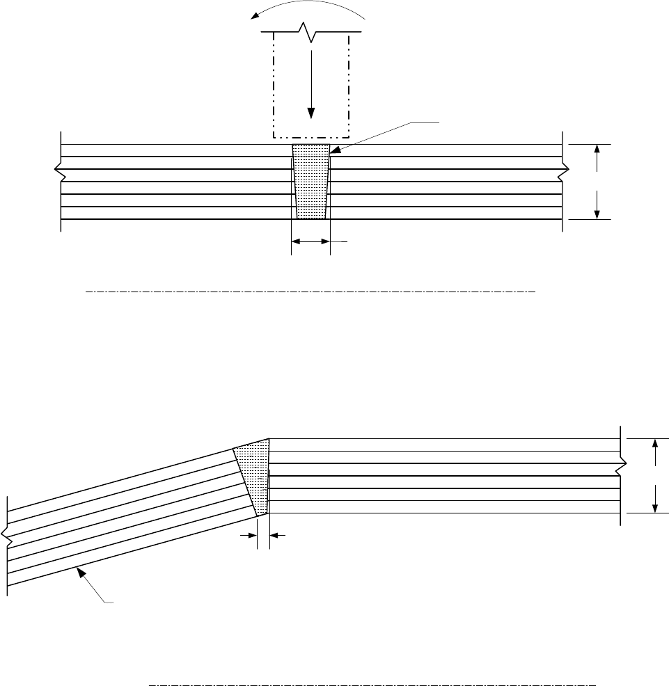
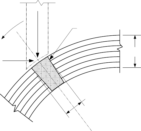
geometry. Examples of an SCP and SCL are given in Figure 5.A.1 and Figure 5.A.2.
c) The following three approaches are provided for linearization of finite element results.
1) Stress Integration Method – This method can be used to linearize stress results from continuum
finite element models [Ref. WRC-429].
2) Structural Stress Method Based on Nodal Forces – This method is based on processing of nodal
forces, and has been shown to be mesh insensitive and correlate well with welded fatigue data [Ref.
WRC-474].
3) Structural Stress Method Based on Stress Integration – This method utilizes the Stress Integration
Method, but restricts the set of elements that contribute to the line of nodes being processed.
d) The Structural Stress Method based on Stress Integration is recommended unless another method can
be shown to produce a more accurate assessment for the given component and loading condition. This
method matches the Structural Stress Method Based on Nodal Forces, which is insensitive to mesh
refinement. In addition, this method can be performed with post-processing tools typically provided by
commercial finite element analysis software.
5.A.3 Selection of Stress Classification Lines
a) Pressure vessels usually contain structural discontinuity regions where abrupt changes in geometry,
material or loading occur. These regions are typically the locations of highest stress in a component.
For the evaluation of failure modes of plastic collapse and ratcheting, Stress Classification Lines (SCLs)
are typically located at gross structural discontinuities. For the evaluation of local failure and fatigue,
SCLs are typically located at local structural discontinuities.
2010 SECTION VIII, DIVISION 2
5-58
b) For SCLs that span a material discontinuity (e.g. base metal with cladding), the SCL should include all
materials and associated loadings. If one of the materials, such as cladding, is neglected for strength
calculations, then only the base metal thickness should be used to calculate the membrane and bending
stresses from the linearized forces and moments across the full section for the evaluation of plastic
collapse.
c) To most accurately determine the linearized membrane and bending stresses for comparison to elastic
stress limits, the following guidelines should be followed. These guidelines can be used as a qualitative
means to evaluate the applicability of different SCLs. Failure to comply with any of these criteria may not
produce valid membrane and/or bending stresses. Application of the limit load or elastic-plastic analysis
methods in Part 5 is recommended for cases where elastic stress analysis and stress linearization may
produce ambiguous results.
1) SCLs should be oriented normal to contour lines of the stress component of highest magnitude.
However, as this may be difficult to implement, similar accuracy can be obtained by orienting the
SCL normal to the mid-surface of the cross section. SCL orientation guidelines are shown in Figure
5.A.3.
2) Hoop and meridional component stress distributions on the SCL should be monotonically increasing
or decreasing, except for the effects of stress concentration or thermal peak stresses, see Figure
5.A.3.b.
3) The distribution of the through-thickness stress should be monotonically increasing or decreasing.
For pressure loading the through-thickness stress should be equal to the compressive pressure on
the applied surface, and approximately zero on the other surface defining the SCL (see Figure
5.A.3.c). When the SCL is not perpendicular to the surfaces, this requirement will not be satisfied.
4) The shear stress distribution should be parabolic and/or the stress should be low relative to the
hoop and meridional stresses. Depending on the type of loading, the shear stress should be
approximately zero on both surfaces defined by the SCL. Guidelines are provided in Figure 5.A.3.d.
i) The shear stress distribution along an SCL will approximate a parabolic distribution only when
the inner and outer surfaces are parallel and the SCL is normal to the surfaces. If the surfaces
are not parallel or an SCL is not normal to the surfaces, the appropriate shear distribution will
not be obtained. However, if the magnitude of shear stress is small as compared to the hoop
or meridional stresses, this orientation criterion can be waived.
ii) When the shear stress distribution is approximately linear, the shear stress is likely to be
significant.
5) For pressure boundary components, the hoop or meridional stresses typically are the largest
magnitude component stresses and are the dominant terms in the equivalent stress. Typically the
hoop or meridional stresses deviate from a monotonically increasing or decreasing trend along an
SCL if the SCL is skewed with respect to the interior, exterior, or mid surfaces. For most pressure
vessel applications, the hoop or meridional stresses due to pressure should be nearly linear.
5.A.4 Stress Integration Method
5.A.4.1 Continuum Elements
5.A.4.1.1 Overview
Stress results derived from a finite element analysis utilizing two-dimensional or three-dimensional continuum
elements may be processed using the stress integration method. Stress components are integrated along
SCLs through the wall thickness to determine the membrane and bending stress components. The peak
stress components can be derived directly using this procedure by subtracting the membrane plus bending
stress distribution from the total stress distribution. Using these components, the equivalent stress shall be
computed per Equation (5.1).
标准分享网 www.bzfxw.com 免费下载