ASME Section VIII div 2 2010. ASME Boiler and Pressure Vessel Code. Alternative Rules
Подождите немного. Документ загружается.

2010 SECTION VIII, DIVISION 2
4-135
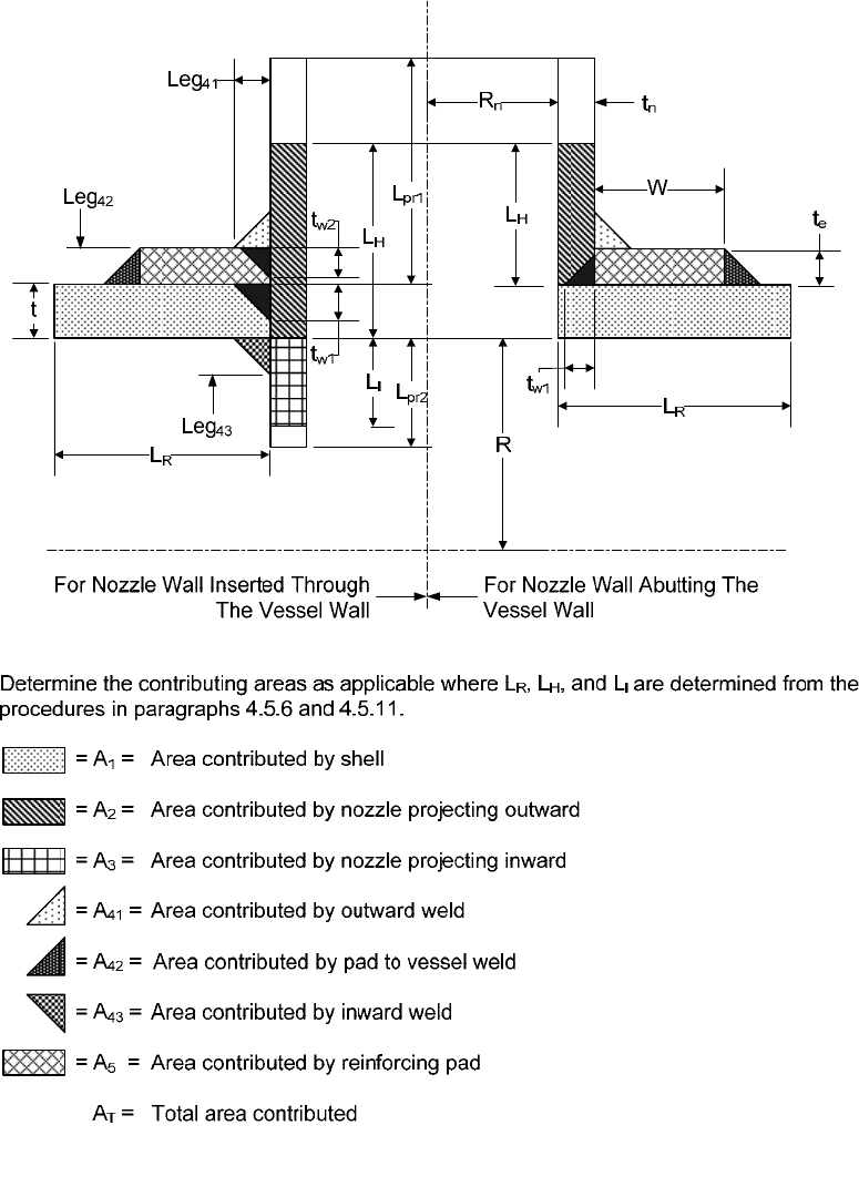
4.5.20 Figures
Notes: 1. Do not include any area that falls outside of the limits defined by L
H
, L
R
, and L
I
. Fo
r
example, if W ≥ L
R
, then W = L
R
and A
42
= 0.0.
2. In accordance paragraph 4.1.4.1, all dimensions are in the corroded condition.
Figure 4.5.1 – Nomenclature for Reinforced Openings
2010 SECTION VIII, DIVISION 2
4-136
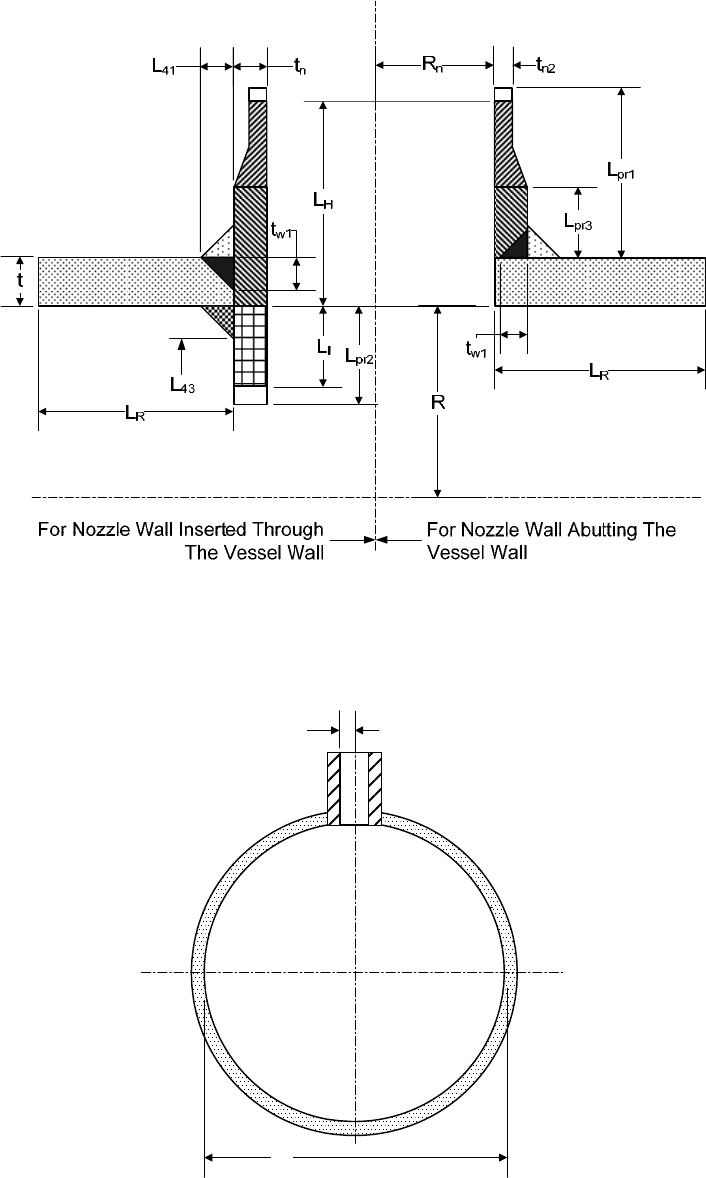
Figure 4.5.2 – Nomenclature for Variable Thickness Openings
R
n
D
i
Figure 4.5.3 – Radial Nozzle in a Cylindrical Shell
标准分享网 www.bzfxw.com 免费下载
2010 SECTION VIII, DIVISION 2
4-137
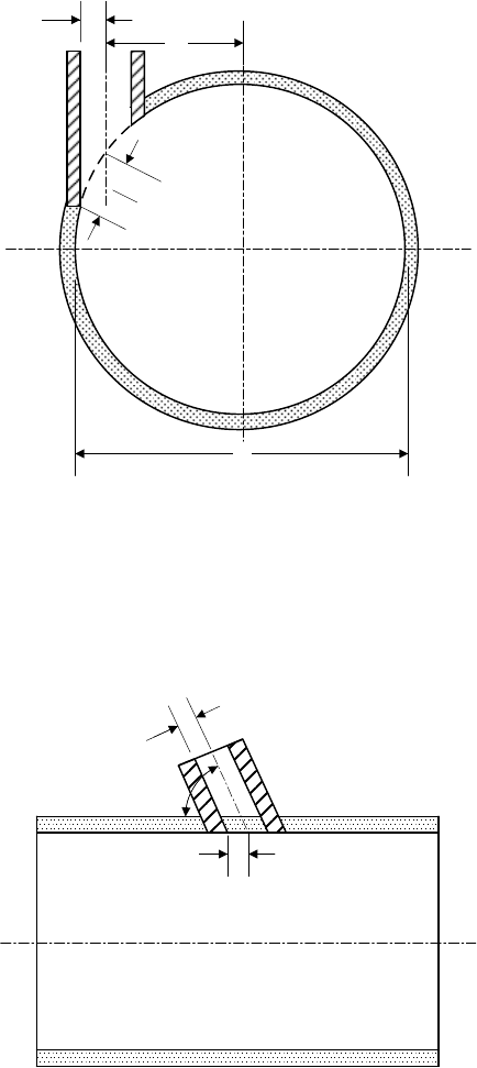
D
x
R
n
D
i
R
nc1
Figure 4.5.4 – Hillside Nozzle in a Cylindrical Shell
R
R
nc
θ
Figure 4.5.5 – Nozzle in a Cylindrical Shell Oriented at an Angle from the Longitudinal Axis
2010 SECTION VIII, DIVISION 2
4-138
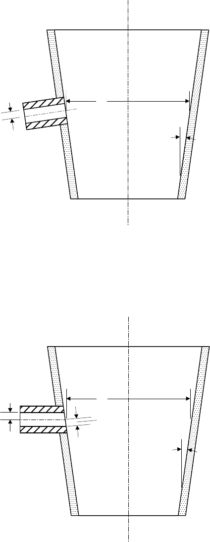
D
i
R
n
α
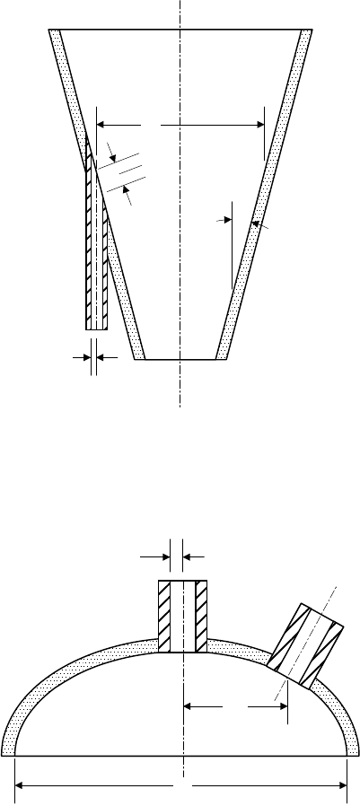
Figure 4.5.6 – Radial Nozzle in a Conical Shell
D
i
R
nc
R
n
α
Figure 4.5.7 – Nozzle in a Conical Shell Oriented Perpendicular to the Longitudinal Axis
标准分享网 www.bzfxw.com 免费下载
2010 SECTION VIII, DIVISION 2
4-139
D
i
R
nc
R
n
α
Figure 4.5.8 – Nozzle in a Conical Shell Oriented Parallel to the Longitudinal Axis
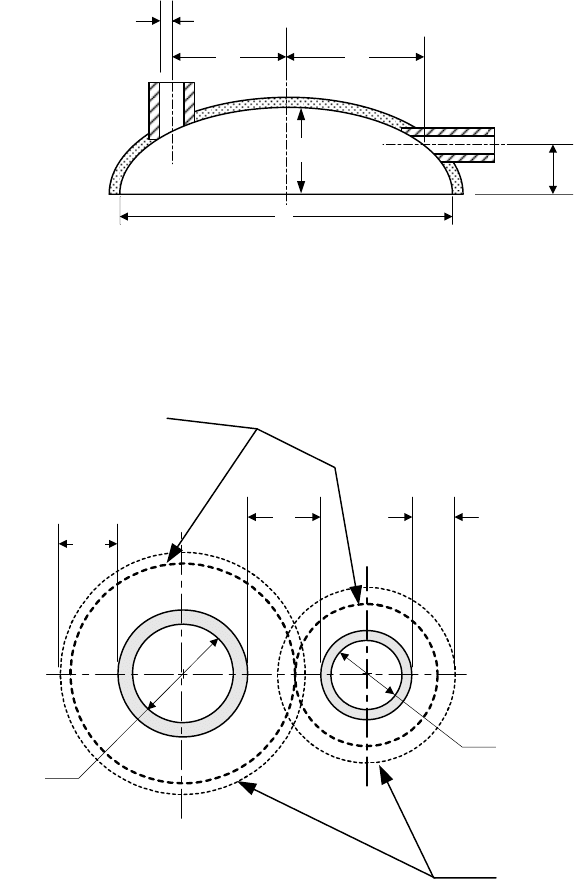
D
i
D
R
R
n
Figure 4.5.9 – Radial Nozzle in a Formed Head
2010 SECTION VIII, DIVISION 2
4-140
D
R
R
n
D
R
h
D
i
D
T
Figure 4.5.10 – Hillside or Perpendicular Nozzle in a Formed Head
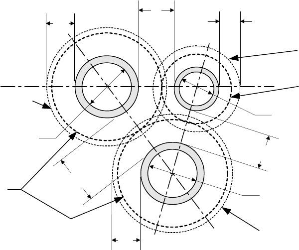
L
s
Nozzle A
Nozzle B
Initial Calculated
Limits of
Reinforcement
Modified Limits of
Reinforcement
L
Rb
L
Ra
2R
na
2R
nb
Figure 4.5.11 – Example of Two Adjacent Nozzle Openings
标准分享网 www.bzfxw.com 免费下载
2010 SECTION VIII, DIVISION 2
4-141
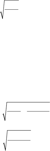
Nozzle A
Nozzle B
2R
nb
L
Rc
2R
nc
Nozzle C
L
S2
L
S3
L
s
L
Ra
2R
na
L
Rb
Modified Limits of
Reinforcement
Modified Limits of
Reinforcement
Initial Calculated Limits
of Reinforcement
Initial Calculated Limits
of Reinforcement
Initial Calculated Limits
of Reinforcement
Figure 4.5.12 – Example of Three Adjacent Nozzle Openings
2010 SECTION VIII, DIVISION 2
4-142
4.6 Design Rules for Flat Heads
4.6.1 Scope
4.6.1.1 The minimum thickness of unstayed flat heads, cover plates and blind flanges shall conform to
the requirements given in paragraph 4.6. These requirements apply to both circular and noncircular heads
and covers. Some acceptable types of flat heads and covers are shown in Table 4.6.1. In this table, the
dimensions of the component parts and the dimensions of the welds are exclusive of extra metal required for
corrosion allowance.
4.6.1.2 The design methods in this paragraph provide adequate strength for the design pressure. A
greater thickness may be necessary if a deflection criterion is required for operation (e.g. leakage at threaded
or gasketed joints).
4.6.1.3 For flat head types with a bolted flange connection where the gasket is located inside the bolt
circle, calculations shall be made for two design conditions, gasket seating and operating conditions. Details
regarding computation of design bolt loads for these two conditions are provided in paragraph 4.16.
4.6.2 Flat Unstayed Circular Heads
4.6.2.1 Circular blind flanges conforming to any of the flange standards listed in Part 1 and the
requirements of paragraph 4.1.11 are acceptable for the diameters and pressure-temperature ratings in the
respective standard when the blind flange is of the types shown in Table 4.6.1, Detail 7.
4.6.2.2 The minimum required thickness of a flat unstayed circular head or cover that is not attached with
bolting that results in an edge moment shall be calculated by the following equation.
ho
CP
td
SE
=
(4.6.1)
4.6.2.3 The minimum required thickness of a flat unstayed circular head, cover, or blind flange that is
attached with bolting that results in an edge moment (see Table 4.6.1, Detail 7) shall be calculated by the
equations shown below. The operating and gasket seating bolt loads,
o
W and
g
W , and the moment arm of
this load,
G
h , in these equations shall be computed based on the flange geometry and gasket material as
described in paragraph 4.16.
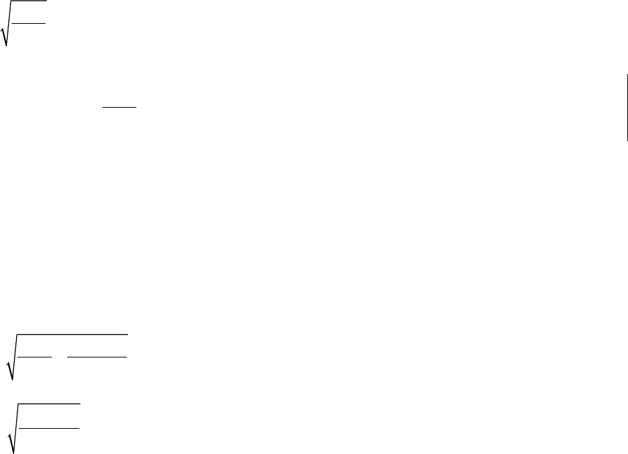
max ,
og
ttt
⎡⎤
=
⎣⎦
(4.6.2)
where
3
1.9
oG
o
ho ho
Wh
CP
td
SE SEd
=+
(4.6.3)
3
1.9
g
G
g
hg
Wh
td
SEd
=
(4.6.4)
标准分享网 www.bzfxw.com 免费下载
2010 SECTION VIII, DIVISION 2
4-143
4.6.3 Flat Unstayed Non-Circular Heads
4.6.3.1 The minimum required thickness of a flat unstayed non-circular head or cover that is not attached
with bolting that results in an edge moment shall be calculated by the following equation.
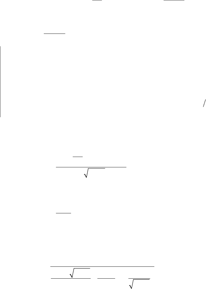
ho
Z
CP
td
SE
=
(4.6.5)
where
2.4
min 2.5, 3.4
d
Z
D
⎡⎤
⎛⎞
=−
⎜⎟
⎢⎥
⎝⎠
⎣⎦
(4.6.6)
4.6.3.2 The minimum required thickness of a flat unstayed non-circular head, cover, or blind flange that
is attached with bolting that results in an edge moment (see Table 4.6.1, Detail 7) shall be calculated by the
equations shown below. The operating and gasket seating bolt loads,
o
W and
g
W
, and the moment arm of
this load,
G
h , in these equations shall be computed based on the flange geometry and gasket material as
described in paragraph 4.16.
max ,
og
ttt
⎡⎤
=
⎣⎦
(4.6.7)
where
2
6
oG
o
ho ho
Wh
ZCP
td
SE SELd
=+
(4.6.8)
2
6
gG
g
hg
Wh
td
SELd
=
(4.6.9)
The parameter
Z
is given by Equation (4.6.6).
4.6.4 Integral Flat Head With A Centrally Located Opening
4.6.4.1 Flat heads which have a single, circular, centrally located opening that exceeds one-half of the
head diameter shall be designed in accordance with the rules which follow. A general arrangement of an
integral flat head with or without a nozzle attached at the central opening is shown in Figure 4.6.1.
a) The shell-to-flat head juncture shall be integral, as shown in Table 4.6.1, Details 1, 2, 3, and 4.
Alternatively, a butt weld, or a full penetration corner weld similar to the joints shown in Table 4.6.1
Details 5 and 6 may be used.
b) The central opening in the flat head may have a nozzle that is integral or integrally attached by a full
penetration weld, or a nozzle attached by non-integral welds (i.e.: a double fillet or partial penetration
weld, or may have an opening without an attached nozzle or hub. In the case of a nozzle attached by
non-integral welds, the head is designed as a head without an attached nozzle or hub.
4.6.4.2 The head thickness does not have to meet the rules in paragraphs 4.6.2 or 4.6.3. The flat head
thickness and other geometry parameters need only satisfy the allowable stress limits in Table 4.6.3.
2010 SECTION VIII, DIVISION 2
4-144
4.6.4.3 A procedure that can be used to design an integral flat head with a single, circular centrally
located opening is shown below.
a) STEP 1 – Determine the design pressure and temperature of the flat head opening.
b) STEP 2 – Determine the geometry of the flat head opening (see Figure 4.6.1).
c) STEP 3 – Calculate the operating moment,
o
M
, using the following equation.
222
11
0.785 0.785( )
22
nn
on sn
gRg
MBPR BBP
+
⎛⎞ ⎛⎞
=++−
⎜⎟ ⎜⎟
⎝⎠ ⎝⎠
(4.6.10)
where
1
2
sn
n
BB
R
g
−
=−
(4.6.11)
d) STEP 4 – Calculate
F , V , and
f
based on
n
B
,
1n
g ,
0n
g and
n
h using the equations in Table 4.16.4
and Table 4.16.5, designate the resulting values as
n
F ,
n
V , and
n
f
.
e) STEP 5 – Calculate F , V , and
f
based on
s
B
,
1
s
g ,
0
s
g and
s
h using the equations in Table 4.16.4
and Table 4.16.5, designate the resulting values as
s
F ,
s
V , and
s
f
.
f) STEP 6 – Calculate Y , T , U ,
Z
, L , e , and d based on
n
KAB
=
using the equations in Table
4.16.4.
g) STEP 7 – Calculate the quantity
()
*
E
θ
using one of the following equations:
For an opening with an integrally attached nozzle:
()
()
2
1
0
*
0
0.91
n
nnn
on
H
nnn
g
BgV
g
ES
fBg
θ
⎛⎞
+
⎜⎟
⎝⎠
=
(4.6.12)
Where
H
S is evaluated using the equation in Table 4.6.2.
For an opening without an attached nozzle or with a nozzle or hub attached with non-integral welds:
()
*
nT
BS
E
t
θ
= (4.6.13)
Where
T
S is evaluated using the equation in Table 4.6.2.
h) STEP 8 – Calculate the quantity
H
M
using the following equation:
()
()
()
*
*
0
3
00
0
1.74
1
H
sss
s
ss s o
ss
E
M
E
VBg
Ft
gBg M
Bg
θ
θ
=
⎛⎞
++
⎜⎟
⎜⎟
+
⎝⎠
(4.6.14)
标准分享网 www.bzfxw.com 免费下载
