ASME Section VIII div 2 2010. ASME Boiler and Pressure Vessel Code. Alternative Rules
Подождите немного. Документ загружается.

2010 SECTION VIII, DIVISION 2
4-145
i) STEP 9 – Calculate the quantity
1
X
using the following equation:
0
1
1
s
oH
ss
o
Ft
MM
Bg
X
M
⎛⎞
−+
⎜⎟
⎜⎟
⎝⎠
=
(4.6.15)
j) STEP 10 – Calculate the stresses at the shell-to-flat head junction and opening-to-flat-head junction
using Table 4.6.2.
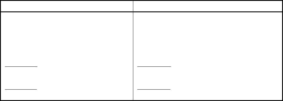
k) STEP 11 – Check the flange stress acceptance criteria in Table 4.6.3. If the stress criteria are satisfied,
then the design is complete. If the stress criteria are not satisfied, then re-proportion the flat head and/or
opening dimensions and go to STEP 3.
4.6.5 Nomenclature
A shell outside diameter.
s
B
inside diameter of the shell.
n
B
inside diameter of the opening.
C
factor depending upon the method of attachment of head, shell dimensions, and other items
as described in Table 4.6.1. It should be noted that the value of
C for a welded cover
includes a factor of 0.667 that effectively increases the allowable stress for such
constructions to 1.5S.
D is the long span of noncircular heads or covers measured perpendicular to short span.
d diameter, or short span, measured as indicated in figure shown in Table 4.6.1.
E joint factor.
e flange stress factor.
n
f
hub stress correction factor for the nozzle opening-to-flat head junction.
s
f
hub stress correction factor the shell-to-flat head junction
E weld joint factor (see paragraph 4.2).
n
F flange stress factor for the nozzle opening-to-flat head junction.
s
F flange stress factor for the shell-to-flat head junction
1
s
g hub thickness at the large end of the shell-to-flat head junction.
0n
g hub thickness at the small end of the nozzle opening-to-flat head junction.
0
s
g hub thickness at the small end of the shell-to-flat head junction.
1n
g hub thickness at the large end of the nozzle opening-to-flat head junction.
1
s
g hub thickness at the large end of the shell-to-flat head junction.
G
h gasket moment arm (see Table 4.16.6).
n
h hub length at the large end of the nozzle opening-to-flat head junction.
s
h hub length at the large end of the shell-to-flat head junction.
L perimeter of a noncircular bolted head measured along the centers of the bolt holes, or the
flange stress factor, as applicable.
o
M
operating moment.
H
M
moment acting at the shell-to-flat head junction.

2010 SECTION VIII, DIVISION 2
4-146
m thickness ratio
rs
tt.
P internal design pressure.
r
inside corner radius on a head formed by flanging or forging.
ho
S allowable stress from Annex 3.A for the head evaluated at the design temperature.
hg
S allowable stress from Annex 3.A for the head evaluated at the gasket seating condition.
T flange stress factor.
t minimum required thickness of the flat head or cover.
g
t
required thickness of the flat head or cover for the gasket seating condition.
o
t required thickness of the flat head or cover for the design operating condition.
f
t nominal thickness of the flange on a forged head at the large end.
h
t nominal thickness of the flat head or cover.
r
t required thickness of a seamless shell.
s
t nominal thickness of the shell.
1
t throat dimension of the closure weld
U flange stress factor.
n
V flange stress factor for the nozzle opening-to-flat head junction.
s
V flange stress factor for the shell-to-flat head junction
o
W operating bolt load at the design operating condition.
g
W gasket seating bolt load at the design gasket seating condition.
Y length of the flange of a flanged head, measured from the tangent line of knuckle, or the
flange stress factor, as applicable.
Z
factor for noncircular heads and covers that depends on the ratio of short span to long span,
or the flange stress factor, as applicable.
1
Z
integral flat head stress parameter.
()
*
E
θ
slope of head with central opening or nozzle times the modulus of elasticity, disregarding the
interaction of the integral shell at the outside diameter of the head.
标准分享网 www.bzfxw.com 免费下载
2010 SECTION VIII, DIVISION 2
4-147
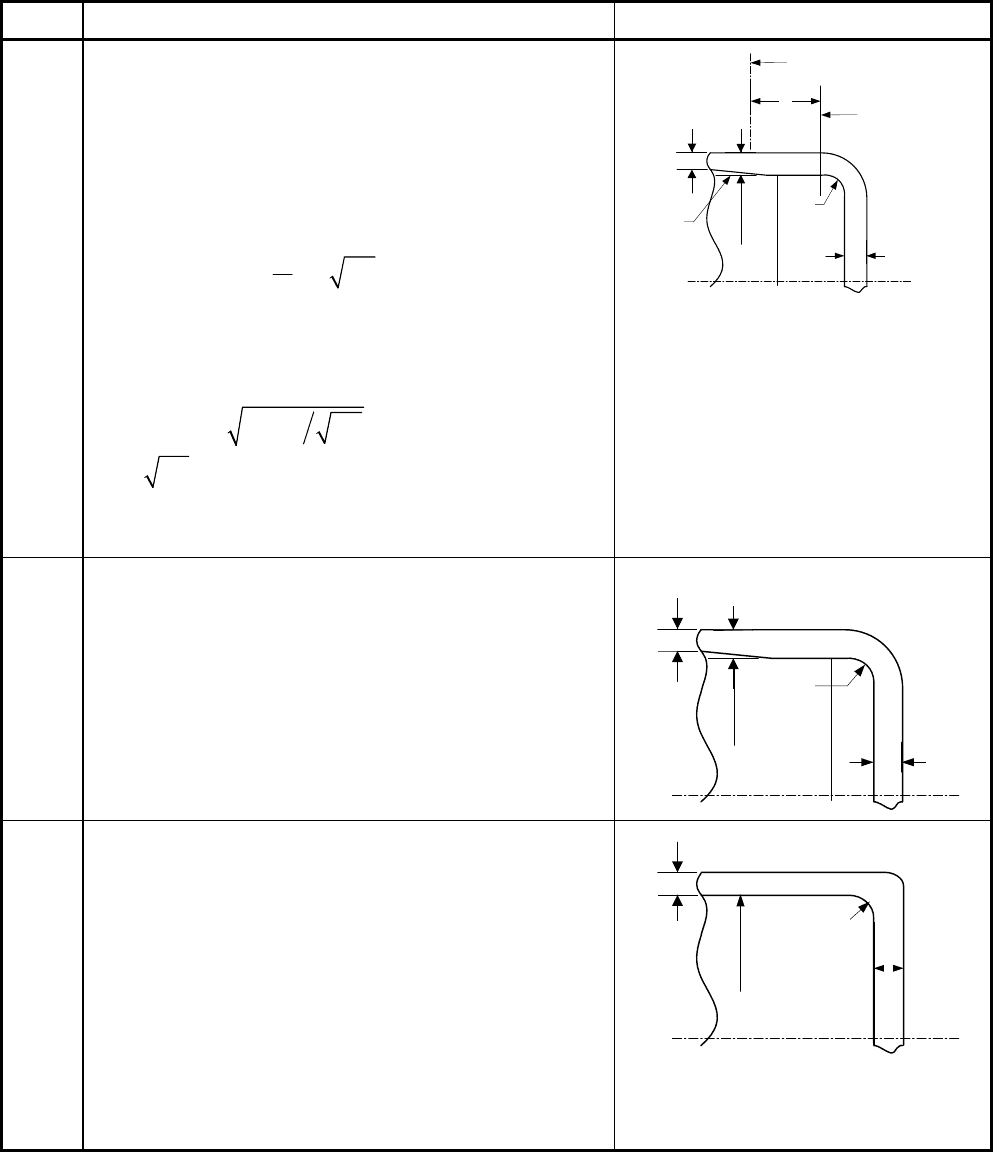
4.6.6 Tables
Table 4.6.1 – C Parameter for Flat Head Designs
Detail Requirements Figure
1
•
0.17C = for flanged circular and noncircular heads
forged integral with or butt welded to the vessel with
an inside corner radius not less than three times the
required head thickness, with no special requirement
with regard to length of flange.
•
0.10C = for circular heads, when the flange length
for heads of the above design is not less than:
2
1.1 0.8
s
h
h
t
Ydt
t
⎛⎞
⎛⎞
⎜⎟
=−
⎜⎟
⎜⎟
⎝⎠
⎝⎠
•
0.10C = for circular heads, when the flange length
Y less than the requirements in the above equation
but the shell thickness is not less than:
1.12 1.1
s
hh
ttYdt=− for a length of at least
2
s
dt . When 0.10C = is used, the taper shall be
at least 1:3.
•
3rt=
minimum shall be used
Taper
Y
t
s
Center Of Weld
t
Tangent Line
t
r
d
2
•
0.17C = for forged circular and noncircular heads
integral with or butt welded to the vessel, where the
flange thickness is not less than two times the shell
thickness, the corner radius on the inside is not less
than three times the flange thickness.
•
3
f
rt= minimum shall be used
t
s
t
f
t
r
d
3
•
[
]
max 0.33 , 0.20Cm= for forged circular and
noncircular heads integral with or butt welded to the
vessel, where the flange thickness is not less than
the shell thickness, the corner radius on the inside is
not less than the following:
10 (0.375 .)
38 (1.5 .)
s
rmm in
f
or t mm in
=
≤
(
)
min 0.25 , 19 0.75 .
38 (1.5 .)
s
s
rtmmin
for t mm in
⎡⎤
=
⎣⎦
>
t
s
t
d
r
2010 SECTION VIII, DIVISION 2
4-148
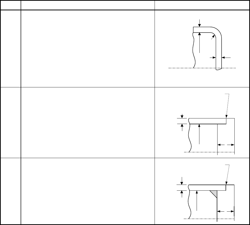
Table 4.6.1 – C Parameter for Flat Head Designs
Detail Requirements Figure
4
•
0.13C =
for integral flat circular heads when:
- the dimension
d does not exceed 610 mm (24 in.)
- the ratio of thickness of the head to the dimension
d is not less than 0.05 or greater than 0.25
- the head thickness
h
t is not less than the shell
thickness
s
t
- the inside corner radius is not less than
0.25t
- the construction is obtained by special techniques
of upsetting and spinning the end of the shell, such
as employed in closing header ends.
•
3rt=
minimum shall be used
t
t
r
d
5
0.33C = for circular plates welded to the end of the
shell when
s
t is at least 1.25
r
t and the weld details
conform to the requirements of paragraph 4.2.
t
d
t
s
See paragraph 4.2 for
detail of weld joint,
t
s
not less than 1.25 t
r
6
[
]
max 0.33 , 0.20Cm=
for circular plates if an inside
fillet weld with minimum throat thickness of
0.7
s
t is used
and the details of the outside weld conform to the
requirements of paragraph 4.2.
t
d
t
s
See paragraph 4.2 for
details of weld joint
标准分享网 www.bzfxw.com 免费下载
2010 SECTION VIII, DIVISION 2
4-149
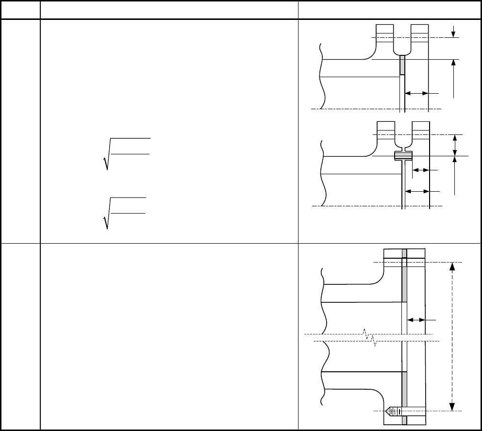
Table 4.6.1 – C Parameter for Flat Head Designs
Detail Requirements Figure
7
•
0.3C =
for circular and noncircular heads and
covers bolted to the vessel as indicated in the
figures.
• When the cover plate is grooved for a peripheral
gasket, the net cover plate thickness under the
groove or between the groove and the outer edge of
the cover plate shall be not less than the following
thickness.
For circular heads and covers:
3
1.9
oG
o
ho
Wh
td
Sd
=
For noncircular heads and covers:
2
6
oG
o
ho
Wh
td
SLd
=
t
d
h
G
t
d
h
G
t
o
8
0.25C = for circular covers bolted with a full-face
gasket to shells and flanges.
t
d
2010 SECTION VIII, DIVISION 2
4-150
Table 4.6.1 – C Parameter for Flat Head Designs
Detail Requirements Figure
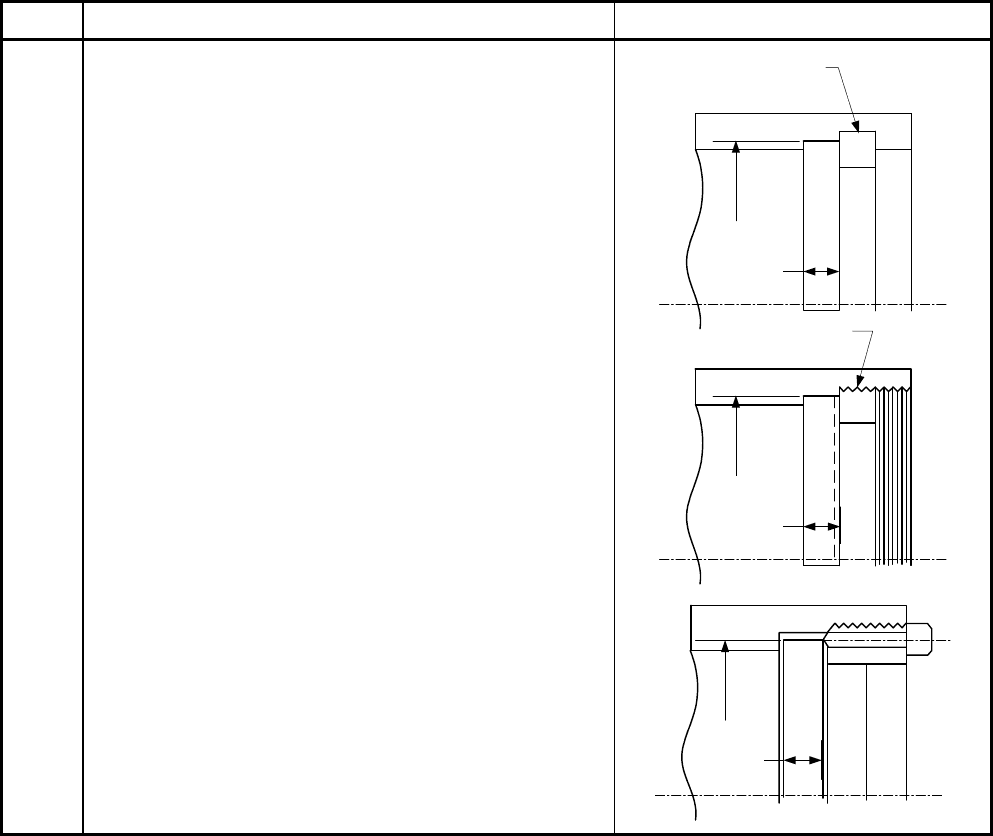
9
0.3C =
for a circular plate inserted into the end of a
vessel and held in place by a positive mechanical locking
arrangement when all possible means of failure (either by
shear, tension, compression, or radial deformation,
including flaring, resulting from pressure and differential
thermal expansion) are resisted with a design factor of at
least four. Seal welding may be used, if desired.
t
d
Retaining Ring
t
d
Threaded Ring
t
d
标准分享网 www.bzfxw.com 免费下载
2010 SECTION VIII, DIVISION 2
4-151
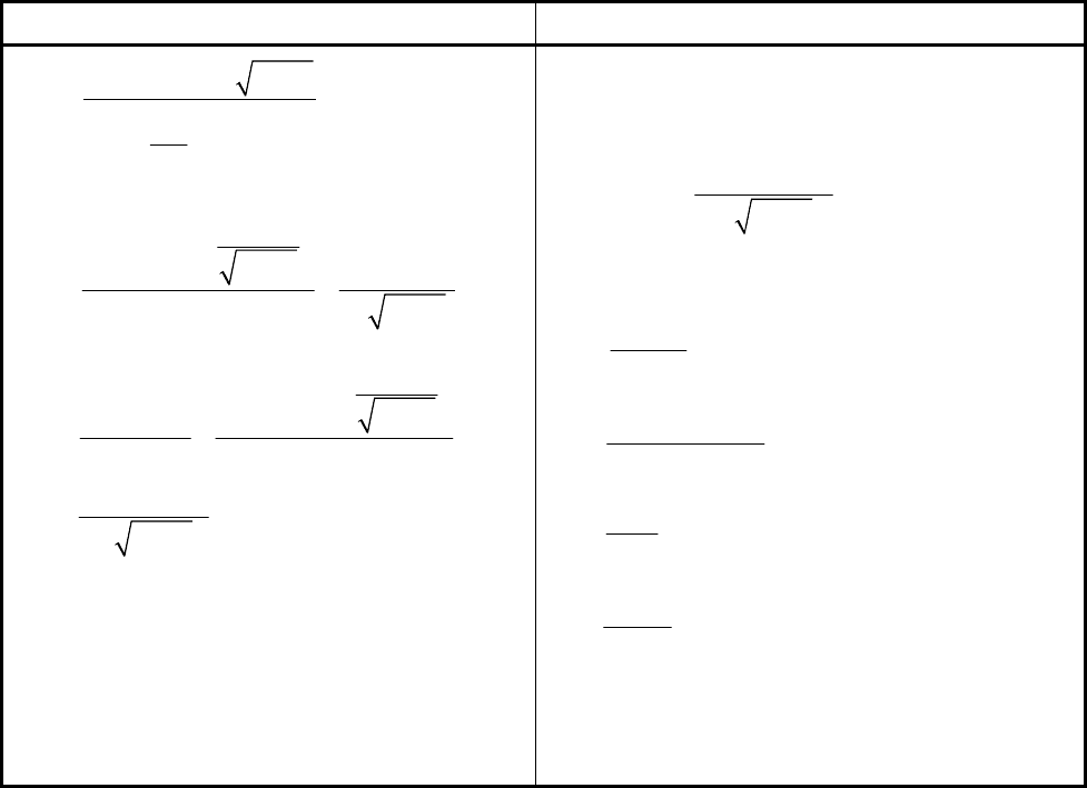
Table 4.6.2 – Junction Stress Equations for an Integral Flat Head With Opening
Head/Shell Junction Stresses Opening/Head Junction Stresses
()
*
10
2
1
0
1.1
sss
HS
s
ss
s
fX E Bg
S
g
BV
g
θ
=
⎛⎞
⎜⎟
⎝⎠
0
2
0
1.91 1
0.64
s
H
ss
sH
RS
s
sss
Ft
M
Bg
FM
S
Bt
BBgt
⎛⎞
+
⎜⎟
⎜⎟
⎝⎠
=+
()
*
0
1
2
0
0.57 1
0.64
s
H
ss
TS
ss
sH
sss
Ft
M
Bg
XE t
S
BBt
ZF M
BBgt
θ
⎛⎞
+
⎜⎟
⎜⎟
⎝⎠
=− +
1HO H
SXS
=
1RO R
SXS
=
1
1
0
0.64
sH
TO T
sss
ZFM
SXS
BBgt
=+
where
2
1
no
H
nn
f
M
S
Lg B
=
(
)
2
1.33 1
o
R
n
te M
S
Lt B
+
=
2
o
TR
n
YM
SZS
tB
=−
2
1
2
2
1
K
Z
K
=
−
Note:
0.0
RH
SS
=
= for the case of an opening
without a nozzle
2010 SECTION VIII, DIVISION 2
4-152
Table 4.6.3 – Stress Acceptance Criteria for an Integral Flat Head With Opening
Head/Shell Junction Stresses Opening/Head Junction Stresses
1.5
H
Sho
SS≤
RS ho
SS≤
TS ho
SS≤
()
2
HS RS
ho
SS
S
+
≤
()
2
HS TS
ho
SS
S
+
≤
1.5
H
Oho
SS
≤
RO ho
SS
≤
TO ho
SS
≤
(
)
2
HO RO
ho
SS
S
+
≤
(
)
2
HO TO
ho
SS
S
+
≤
标准分享网 www.bzfxw.com 免费下载
2010 SECTION VIII, DIVISION 2
4-153
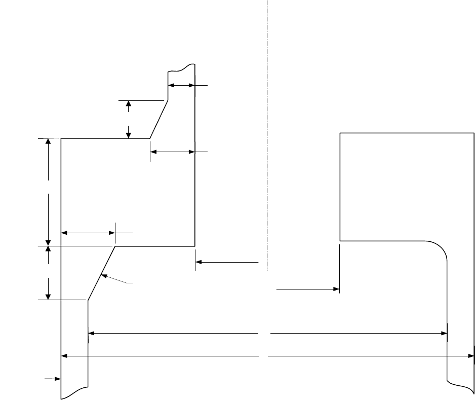
4.6.7 Figures
B
n
For Nozzle
t
h (Shell)
g
o
(Shell)
g
o
(Nozzle)
This Half Depicts
Opening Without Nozzle
B
s
B
n
Without Nozzle
A
g
1
(Nozzle)
g
1
(Nozzle)
This Half Depicts
Opening With Nozzle
h (Nozzle)
Juncture May Or
May Not Have Taper
L
C
Figure 4.6.1 – Integral Flat head With a Large Central Opening

2010 SECTION VIII, DIVISION 2
4-154
4.7 Design Rules for Spherically Dished Bolted Covers
4.7.1 Scope
4.7.1.1 Design rules for four configurations of circular spherically dished heads with bolting flanges are
provided in paragraph 4.7. The four head types are shown in Figures 4.7.1, 4.7.2, 4.7.3, and 4.7.4. The
design rules cover both internal and external pressure, pressure that is concave and convex to the spherical
head, respectively. The maximum value of the pressure differential shall be used in all of the equations.
4.7.1.2 For head types with a bolted flange connection where the gasket is located inside the bolt circle,
calculations shall be made for two design conditions, gasket seating and operating conditions. Details
regarding computation of design bolt loads and flange moments for these two conditions are provided in
paragraph 4.16. If a flange moment is computed as a negative number, the absolute value of this moment
shall be used in all of the equations.
4.7.1.3 Calculations shall be performed using dimensions in the corroded condition and the uncorroded
condition, and the more severe case shall control.
4.7.2 Type A Head Thickness Requirements
4.7.2.1 The thickness of the head and skirt for a Type A Head Configuration (see Figure 4.7.1) shall be
determined in accordance with the rules in paragraph 4.3 for internal pressure (pressure on the concave
side), and paragraph 4.4 for external pressure (for pressure on the convex side). The skirt thickness shall be
determined using the appropriate formula for cylindrical shells. The head radius,
L , and knuckle radius, r ,
shall comply with the limitations given in these paragraphs.
4.7.2.2 The flange thickness of the head for a Type A Head Configuration shall be determined in
accordance with the rules of paragraph 4.16. When a slip-on flange conforming to the standards listed in
Table 1.1 is used, design calculations per paragraph 4.16 need not be done provided the design pressure-
temperature is within the pressure-temperature rating permitted in the flange standard.
4.7.2.3 Detail (a) in Figure 4.7.1 is permitted if both of the following requirements are satisfied.
a) The material of construction satisfies the following equation.
0.625
yT
u
S
S
≤ (4.7.1)
b) The component is not in cyclic service, i.e. a fatigue analysis is not required in accordance with
paragraph 4.1.1.4.
4.7.3 Type B Head Thickness Requirements
4.7.3.1 The thickness of the head for a Type B Head Configuration (see Figure 4.7.2) shall be
determined by the following equations.
a) Internal pressure (pressure on the concave side)
5
6
PL
t
S
=
(4.7.2)
b) External pressure (pressure on the convex side) – the head thickness shall be determined in accordance
with the rules in paragraph 4.4.
标准分享网 www.bzfxw.com 免费下载
