ASME Section VIII div 2 2010. ASME Boiler and Pressure Vessel Code. Alternative Rules
Подождите немного. Документ загружается.


2010 SECTION VIII, DIVISION 2
4-165
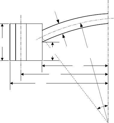
T
B/2
C/2
t
A/2
R
q
φ
Figure 4.7.5 – Type D Head Geometry for Alternative Design Procedure
2010 SECTION VIII, DIVISION 2
4-166
4.8 Design Rules for Quick-Actuating (Quick Opening) Closures
4.8.1 Scope
4.8.1.1 Design requirements for quick-actuating or quick-opening closures are provided in Paragraph
4.8. Specific calculation methods are not provided. However, the rules of Part 4 and Part 5 can be used to
qualify the design of a quick-actuating or quick-opening closure.
4.8.2 Definitions
4.8.2.1 Quick-actuating or quick-opening closures are those that permit substantially faster access to the
contents space of a pressure vessel than would be expected with a standard bolted flange connection
(bolting through one or both flanges). Closures with swing bolts are not considered quick actuating (quick-
opening).
4.8.2.2 Holding elements are structural members of the closure used to attach or hold the cover to the
vessel, and/or to provide the load required to seal the closure. Hinge pins or bolts can be holding elements.
4.8.2.3 Locking components are parts of the closure that prevent a reduction in the load on a holding
element that provides the force required to seal the closure, or prevent the release of a holding element.
Locking components may also be used as holding elements.
4.8.2.4 The locking mechanism or locking device consists of a combination of locking components.
4.8.2.5 The use of a multi-link component, such as a chain, as a holding element is not permitted.
4.8.3 General Design Requirements
4.8.3.1 Quick-actuating closures shall be designed such that the locking elements will be engaged prior
to or upon application of the pressure and will not disengage until the pressure is released.
4.8.3.2 Quick-actuating closures shall be designed such that the failure of a single locking component
while the vessel is pressurized (or contains a static head of liquid acting at the closure) will not:
a) Cause or allow the closure to be opened or leak; or
b) Result in the failure of any other locking component or holding element; or
c) Increase the stress in any other locking component or holding element by more than 50% above the
allowable stress of the component.
4.8.3.3 Quick-actuating closures shall be designed and installed such that it may be determined by visual
external observation that the holding elements are in satisfactory condition.
4.8.3.4 Quick-actuating closures shall also be designed so that all locking components can be verified to
be fully engaged by visual observation or other means prior to the application of pressure to the vessel.
4.8.3.5 When installed, all vessels having quick-actuating closures shall be provided with a pressure-
indicating device visible from the operating area and suitable to detect pressure at the closure.
标准分享网 www.bzfxw.com 免费下载
2010 SECTION VIII, DIVISION 2
4-167
4.8.4 Specific Design Requirements
4.8.4.1 Quick-actuating closures that are held in position by positive locking devices and that are fully
released by partial rotation or limited movement of the closure itself or the locking mechanism and any
closure that is other than manually operated shall be so designed that when the vessel is installed the
following conditions are met:
a) The closure and its holding elements are fully engaged in their intended operating position before
pressure can be applied in the vessel.
b) Pressure tending to force the closure open or discharge the contents clear of the vessel shall be
released before the closure can be fully opened for access.
c) In the event that compliance with paragraphs 4.8.4.1.a and 4.8.4.1.b above is not inherent in the design
of the closure and its holding elements, provisions shall be made so that devices to accomplish this can
be added when the vessel is installed.
4.8.4.2 The design rules of paragraph 4.16 of this code may not be applicable to design Quick-Actuating
or Quick-Opening Closures, see paragraph 4.16.1.4.
4.8.4.3 The designer shall consider the effects of cyclic loading, other loadings (see paragraph 4.1.5.3)
and mechanical wear on the holding and locking components.
4.8.4.4 It is recognized that it is impractical to write requirements to cover the multiplicity of devices used
for quick access, or to prevent negligent operation or the circumventing of safety devices. Any device or
devices that will provide the safeguards broadly described in paragraphs 4.8.4.1.a, 4.8.4.1.b and 4.8.4.1.c
above will meet the intent of this Division.
4.8.5 Alternative Designs for Manually Operated Closures
4.8.5.1 Quick-actuating closures that are held in position by a locking mechanism designed for manual
operation shall be designed such that if an attempt is made to open the closure when the vessel is under
pressure, the closure will leak prior to full disengagement of the locking components and release of the
closure. The design of the closure and vessel shall be such that any leakage shall be directed away from the
normal position of the operator.
4.8.5.2 Manually operated closures need not satisfy paragraphs 4.8.4.1.a, 4.8.4.1.b and 4.8.4.1.c, but
such closures shall be equipped with an audible or visible warning device that will warn the operator if
pressure is applied to the vessel before the holding elements and locking components are fully engaged in
their intended position or if an attempt is made to disengage the locking mechanism before the pressure
within the vessel is released.
4.8.6 Supplementary Requirements for Quick-Actuating (Quick-Opening) Closures
Annex 4.B provides additional design information for the Manufacturer and provides installation, operational,
and maintenance requirements for the Owner.

2010 SECTION VIII, DIVISION 2
4-168
4.9 Design Rules for Braced and Stayed Surfaces
4.9.1 Scope
4.9.1.1 Design requirements for braced and stayed surfaces are provided in this paragraph.
Requirements for the plate thickness and requirements for the staybolt or stay geometry including size, pitch,
and attachment details are provided.
4.9.2 Required Thickness of Braced and Stayed Surfaces
4.9.2.1 The minimum thickness for braced and stayed flat plates and those parts that, by these rules,
require staying as flat plates with braces or staybolts of uniform diameter symmetrically spaced, shall be
calculated by the following equation.
s
P
tp
SC
=
(4.9.1)
4.9.2.2 When stays are used to connect two plates, and only one of these plates requires staying, the
value of
C
shall be governed by the thickness of the plate requiring staying.
4.9.3 Required Dimensions and Layout of Staybolts and Stays
4.9.3.1 The required area of a staybolt or stay at its minimum cross section, usually located at the root of
the thread, exclusive of any corrosion allowance, shall be obtained by dividing the load on the staybolt
computed in accordance with paragraph 4.9.3.2 by the allowable tensile stress value for the staybolt material,
multiplying the result by 1.10.
4.9.3.2 The area supported by a staybolt or stay shall be computed on the basis of the full pitch
dimensions, with a deduction for the area occupied by the stay. The load carried by a stay is the product of
the area supported by the stay and the maximum allowable working pressure. When a staybolt or stay for a
shell is unsymmetrical because of interference with other construction details, the area supported by the
staybolt or stay shall be computed by taking the distance from the center of the spacing on one side of the
staybolt or stay to the center of the spacing on the other side.
4.9.3.3 When the edge of a flat stayed plate is flanged, the distance from the center of the outermost
stays to the inside of the supporting flange shall not be greater than the pitch of the stays plus the inside
radius of the flange.
4.9.4 Requirements for Welded-in Staybolts and Welded Stays
4.9.4.1 Welded-in staybolts may be used provided the following requirements are satisfied.
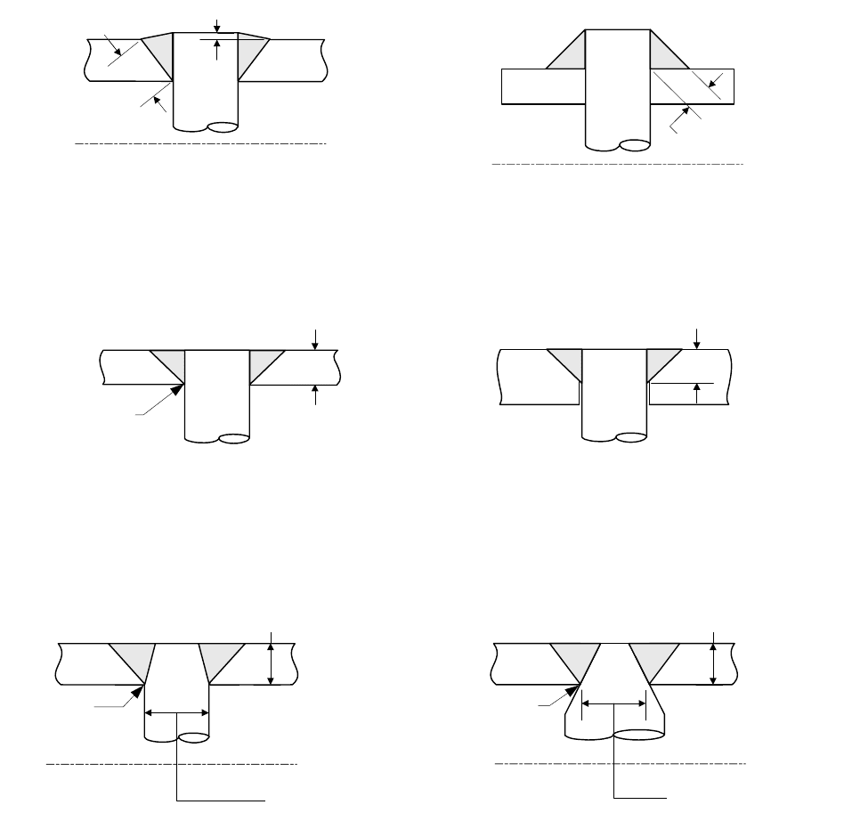
a) The configuration is in accordance with the typical arrangements shown in Figure 4.9.1.
b) The required thickness of the plate shall not exceed 38 mm (1.5 in.).
c) The maximum pitch shall not exceed 15 times the diameter of the staybolt; however, if the required plate
thickness is greater than 19 mm (0.75 in.), the staybolt pitch shall not exceed 508 mm (20 in.).
d) The size of the attachment welds is not less than that shown in Figure 4.9.1.
e) The allowable load on the welds shall not exceed the product of the weld area (based on the weld
dimension parallel to the staybolt), the allowable tensile stress of the material being welded, and a weld
joint factor of 60%.
标准分享网 www.bzfxw.com 免费下载
2010 SECTION VIII, DIVISION 2
4-169
4.9.4.2 Welded stays may be used provided the following requirements are satisfied.
a) The configuration is in accordance with the typical arrangements shown in Figure 4.9.1.
b) The pressure does not exceed 2 MPa (300 psi).
c) The required thickness of the plate does not exceed 13 mm (0.5 in.).
d) The size of the fillet welds is not less than the plate thickness requiring stay.
e) The inside welds are visually examined before the closing plates are attached.
f) The allowable load on the fillet welds shall not exceed the product of the weld area (based on the
minimum leg dimension), the allowable tensile stress of the material being welded, and a weld joint
factor of 55%.
g) The maximum diameter or width of the hole in the plate shall not exceed 32 mm (1.25 in.).
h) The maximum pitch,
s
p
, is determined by Equation (4.9.1) with 2.1C
=
if either plate thickness is less
than or equal to 11 mm (0.4375 in.) thick, and
2.2C
=
for all other plate thicknesses.
4.9.5 Nomenclature
C stress factor for braced and stayed surfaces (see Table 4.9.1).
P design pressure.
s
p
maximum pitch. The maximum pitch is the greatest distance between any set of parallel
straight lines passing through the centers of staybolts in adjacent rows. Each of the three
parallel sets running in the horizontal, the vertical, and the inclined planes shall be
considered.
S allowable stress from Annex 3.A evaluated at the design temperature.
t minimum required plate thickness.
s
t nominal thickness of the thinner stayed plate (see Figure 4.9.1).

2010 SECTION VIII, DIVISION 2
4-170
4.9.6 Tables
Table 4.9.1 – Stress Factor For Braced And Stayed Surfaces
Braced And Stayed Surface Construction
C
Welded stays through plates not over 11 mm (0.4375 in.) in thickness 2.1
Welded stays through plates over 11 mm (0.4375 in.) in thickness 2.2
标准分享网 www.bzfxw.com 免费下载

2010 SECTION VIII, DIVISION 2
4-171
4.9.7 Figures
3 mm (1/8 in.)
t
s
min.
t
s
min.
Complete
Penetration
t
s
t
s
min.
t
s
Complete
Penetration
Diameter Used To
Satisfy Paragraph 4.9.3
t
s
Complete
Penetration
Diameter Used To
Satisfy Paragraph 4.9.3
(a)
(b)
(c)
(d)
(e)
(f)
Note: t
s
is the nominal thickness of the thinner stayed plate
Figure 4.9.1 – Typical Forms of Welded Staybolts

2010 SECTION VIII, DIVISION 2
4-172
4.10 Design Rules for Ligaments
4.10.1 Scope
4.10.1.1 Rules for determining the ligament efficiency for hole patterns in cylindrical shells are covered in
this paragraph. The ligament efficiency or weld joint factor (see paragraph 4.10.3) is used in conjunction with
the design equations for shells in paragraph 4.3.
4.10.2 Ligament Efficiency
4.10.2.1 When a cylindrical shell is drilled for tubes in a line parallel to the axis of the shell for substantially
the full length of the shell as shown in Figures 4.10.1 through 4.10.3, the efficiency of the ligaments between
the tube holes shall be determined as follows.
a) When the pitch of the tube holes on every row is equal (see Figure 4.10.1), the ligament efficiency is:
p
d
E
p
−
= (4.10.1)
b) When the pitch of tube holes on any one row is unequal (as in Figures 4.10.2 and 4.10.3), the ligament
efficiency is:
1
1
p
nd
E
p
−
=
(4.10.2)
c) When the adjacent longitudinal rows are drilled as described in paragraph 4.10.2.1.b, diagonal and
circumferential ligaments shall also be examined. The least equivalent longitudinal efficiency shall be
used to determine the minimum required thickness and the maximum allowable working pressure.
d) When a cylindrical shell is drilled for holes so as to form diagonal ligaments, as shown in Figure 4.10.4,
the efficiency of these ligaments shall be determined by Figures 4.10.5 and 4.10.6. Figure 4.10.5 is
used to determine the efficiency of longitudinal and diagonal ligaments with limiting boundaries where
the condition of equal efficiency of diagonal and longitudinal ligaments form one boundary and the
condition of equal efficiency of diagonal and circumferential ligaments form the other boundary. Figure
4.10.6 is used for determining the equivalent longitudinal efficiency of diagonal ligaments. This efficiency
is used in the equations for setting the minimum required thickness.
1) Figure 4.10.5 is used when either or both longitudinal and circumferential ligaments exist with
diagonal ligaments. To use Figure 4.10.5, compute the value of
1
*
p
p and also the efficiency of
the longitudinal ligament. Next find in the diagram, the vertical line corresponding to the longitudinal
efficiency of the ligament and follow this line vertically to the point where it intersects the diagonal
line representing the ratio of
1
*
p
p . Then project this point horizontally to the left, and read the
diagonal efficiency of the ligament on the scale at the edge of the diagram. The minimum shell
thickness and the maximum allowable working pressure shall be based on the ligament that has the
lower efficiency.
2) Figure 4.10.6 is used for holes that are not in-Iine, or holes that are placed longitudinally along a
cylindrical shell. The diagram may be used for pairs of holes for all planes between the longitudinal
plane and the circumferential plane. To use Figure 4.10.6, determine the angle
θ
between the
longitudinal shell axis and the line between the centers of the openings and compute the value of
*pd
. Find in the diagram, the vertical line corresponding to the value of
θ
and follow this line
vertically to the line representing the value of
*
p
d . Then project this point horizontally to the left,
and read the equivalent longitudinal efficiency of the diagonal ligament. This equivalent longitudinal
标准分享网 www.bzfxw.com 免费下载
2010 SECTION VIII, DIVISION 2
4-173
efficiency is used to determine the minimum required thickness and the maximum allowable
working pressure.
e) When tube holes in a cylindrical shell are arranged in symmetrical groups which extend a distance
greater than the inside diameter of the shell along lines parallel to the axis and the same spacing is used
for each group, the efficiency for one of the groups shall be not less than the efficiency on which the
maximum allowable working pressure is based.
f) The average ligament efficiency in a cylindrical shell, in which the tube holes are arranged along lines
parallel to the axis with either uniform or non-uniform spacing, shall be computed by the following rules
and shall satisfy the requirements of both. These rules only apply to ligaments between tube holes and
not to single openings. They may give lower efficiencies in some cases than those for symmetrical
groups which extend a distance greater than the inside diameter of the shell as covered in paragraph
4.10.2.1.e. When this occurs, the efficiencies computed by the rules under paragraph 4.10.2.1.b shall
govern.
1) For a length equal to the inside diameter of the shell for the position which gives the minimum
efficiency, the efficiency shall be not less than that on which the maximum allowable working
pressure is based. When the inside diameter of the shell exceeds 1520 mm (60 in.), the length
shall be taken as 1520 mm (60 in.), in applying this rule.
2) For a length equal to the inside radius of the shell for the position which gives the minimum
efficiency, the efficiency shall be not less than 80% of that on which the maximum allowable
working pressure is based. When the inside radius of the shell exceeds 762 mm (30 in.), the length
shall be taken as 762 mm (30 in.), in applying this rule.
4.10.3 Ligament Efficiency and the Weld Joint Factor
When ligaments occur in cylindrical shells made from welded pipe or tubes and their calculated efficiency is
less than 85% (longitudinal) or 50% (circumferential), the efficiency to be used in paragraph 4.3 to determine
the minimum required thickness is the calculated ligament efficiency. In this case, the appropriate stress
value in tension may be multiplied by the factor 1.18.
4.10.4 Nomenclature
d diameter of tube holes
E longitudinal ligament efficiency
long
E longitudinal ligament efficiency in percent
p
longitudinal pitch of tube holes
1
p
unit length of ligament
*
p
diagonal pitch of tube holes
θ
angle of the diagonal pitch with respect to the longitudinal line
s longitudinal dimension of diagonal pitch, *cosp
θ
⋅
n number of tube holes in length
1
p

2010 SECTION VIII, DIVISION 2
4-174
4.10.5 Figures
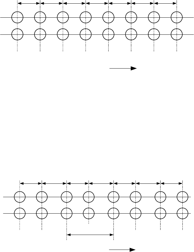
Longitudinal Line
General Note: 133 mm (5-1/4 in.)
133
mm
133
mm
133
mm
133
mm
133
mm
133
mm
133
mm
Figure 4.10.1 – Example of Tube Spacing With the Pitch of Holes Equal in Every Row
Longitudinal Line
General Note: 133 mm (5-1/4 in.)
171 mm (6-3/4 in.)
133
mm
171
mm
133
mm
171
mm
133
mm
171
mm
133
mm
p
1
= 305 mm
(12 in.)
Figure 4.10.2 – Example of Tube Spacing With the Pitch of Holes Unequal in Every Second Row
标准分享网 www.bzfxw.com 免费下载
