ASME Section VIII div 2 2010. ASME Boiler and Pressure Vessel Code. Alternative Rules
Подождите немного. Документ загружается.

2010 SECTION VIII, DIVISION 2
4-105
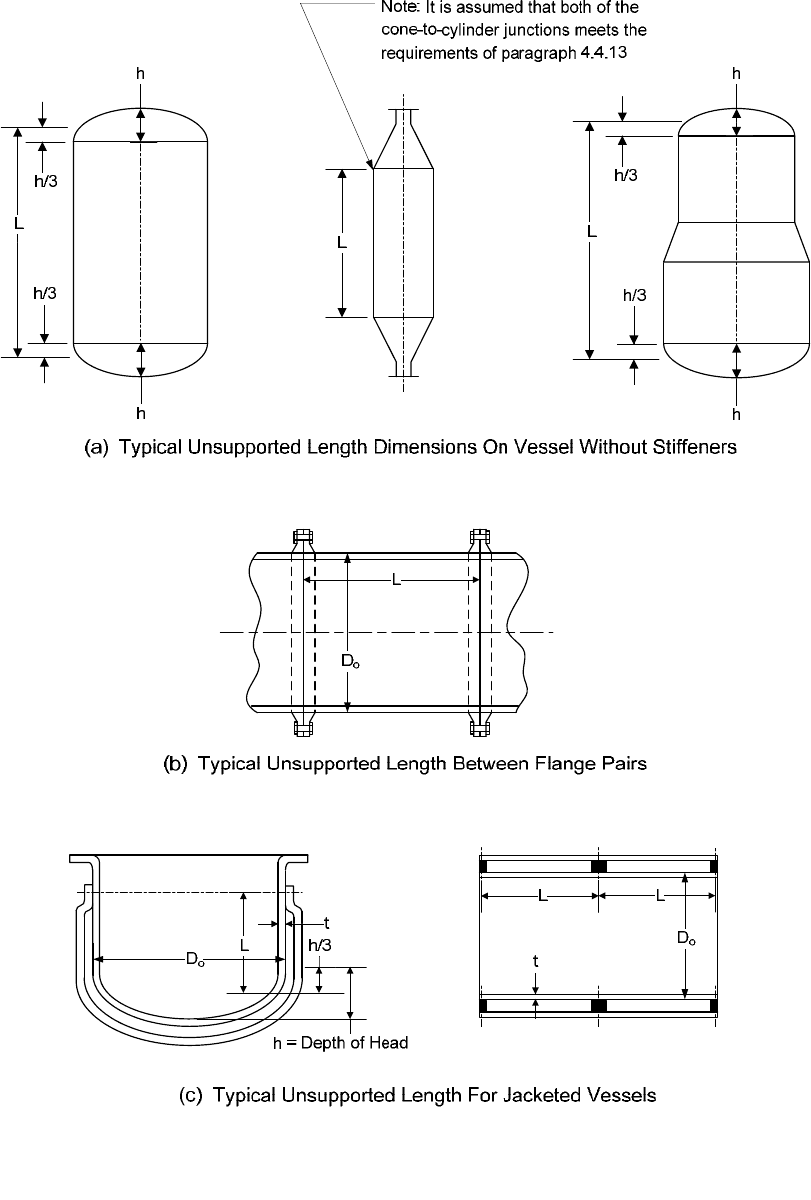
4.4.17 Figures
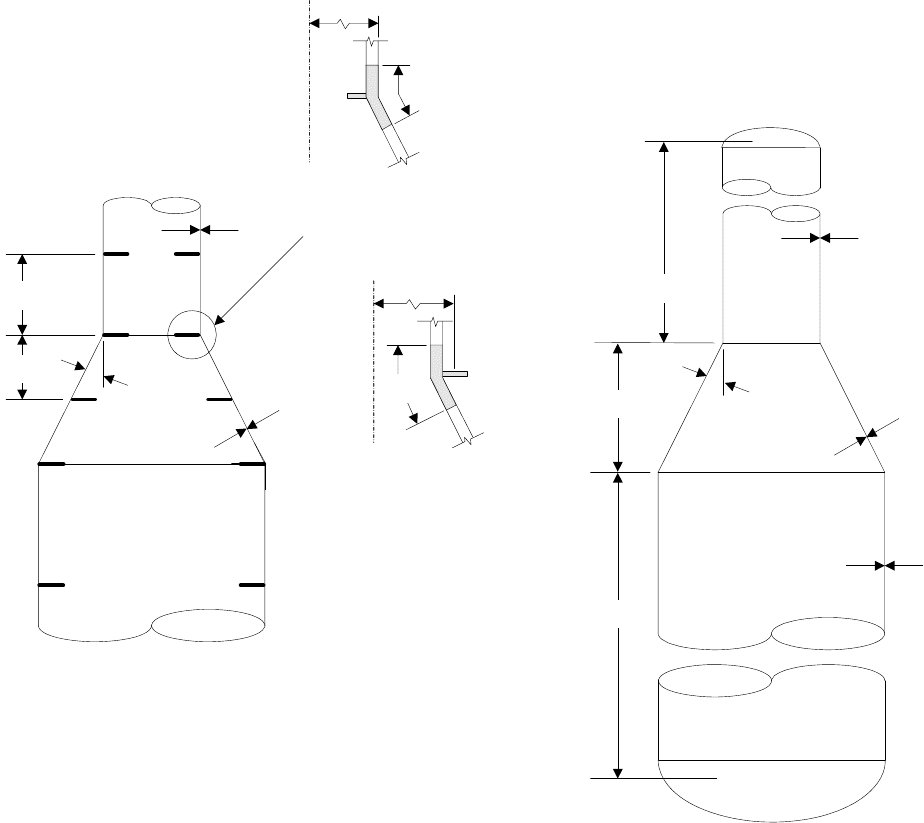
Figure 4.4.1 – Lines of Support or Unsupported Length for Typical Vessel Configurations
2010 SECTION VIII, DIVISION 2
4-106
L=L
t
D
o
h/3
h h
h h
h/3 h/3
Large Ring
(Effective as
Bulkhead)
Head (Effective
as Bulkhead)
(b) Ring Stiffened
(a) Unstiffened
L
L
L
B1
0.5L
B2
L
f
0.5L
B3
0.5L
1
L
S
0.5L
2
L
1
L
2
L
h/3
L
B2
L
B3
L
L
t
D
o
Head
(Effective
as Bulkhead)
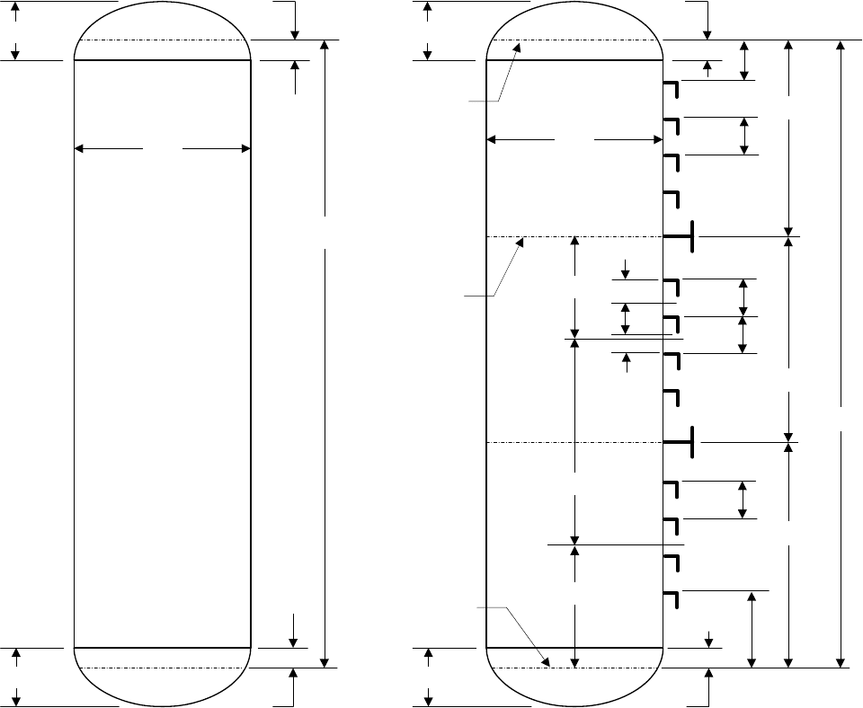
Figure 4.4.2 – Lines of Support or Unsupported Length for Unstiffened and Stiffened Cylindrical
Shells
标准分享网 www.bzfxw.com 免费下载
2010 SECTION VIII, DIVISION 2
4-107
A
L
, I
L
(a) Sections Through Stiffening Rings
A
S
, I
S
(b) Stiffener Variables for Local Buckling Calculation
R
t
R
c
= R + Z
c
L
e
Z
s
Z
c
R
t
R
c
=R+Z
c
L
e
Z
L
Z
c
Shell
t
1
h
1
Shell
t
2
h
2
t
1
h
1
t
2
Shell
h
2
2h
1
t
1
(a-1) Stiffening Ring which
Acts as a Bulkhead
(a-2) Small Stiffening Ring
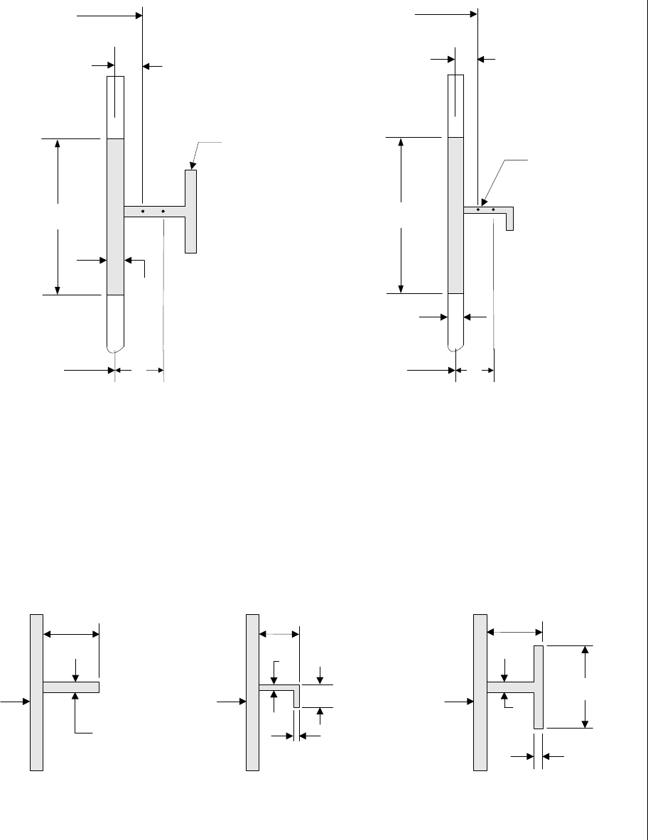
Figure 4.4.3 – Stiffener Ring Parameters
2010 SECTION VIII, DIVISION 2
4-108
This Section Shall
have Moment
Of Inertia Required
For Ring
Butt Weld In Ring
C
Type Of Construction
When Gap Is Greater
Than Length Of Arc
permitted in paragraph
4.4.5.2.g.3
B
K
Unstiffened
Cylinder
At
Least
120°
Support
This section shall have a
moment of inertia required
for the ring unless requirements
parapraph 4.4.5.2.g.2 are met.
Gap
E
F
This section shall have the
moment of inertia required
for the ring.
Length Of Any Gap In
Unsupported Shell Not To
Exceed Length of arc shown in
Figure 4.4.5
(see paragraph 4.4.5.2.g.3)
Section 1-1
Gap in Ring
for Drainage
Butt Weld
D
Strut Member
A
Butt Weld
Gap (Not To Exceed 8
Times The Thicknes
Of The Shell Plate)
Shell
See
paragraph
4.4.5.2.g.3
Butt Weld
In Ring
1
1
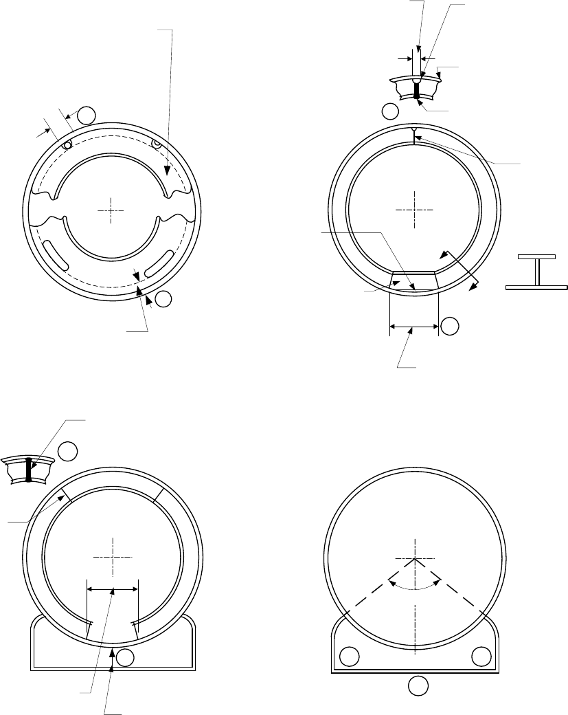
Figure 4.4.4 – Various Arrangements of Stiffening Rings for Cylindrical Vessels Subjected to External
Pressure
标准分享网 www.bzfxw.com 免费下载
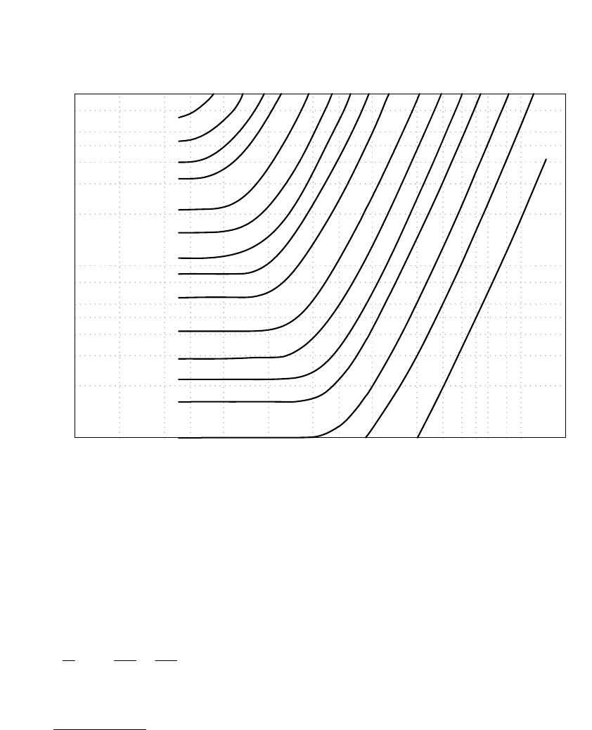
2010 SECTION VIII, DIVISION 2
4-109
Design Length Divided By Outside Diameter, L
ec
/D
o
0.01 0.02 0.040.06 0.1 0.2 0.4 0.6 1 2 3 4 5 6 8 10 20
Outside Diameter Divided By Thickness, D
o
/t
10
20
30
40
50
60
80
100
200
300
400
500
600
800
1000
Arc = 0.030D
O
Arc = 0.035D
O
Arc = 0.040D
O
Arc = 0.045D
O
Arc = 0.055D
O
Arc = 0.065D
O
Arc = 0.075D
O
Arc = 0.085D
O
Arc = 0.010D
O
Arc = 0.125D
O
Arc = 0.150D
O
Arc = 0.175D
O
Arc = 0.200D
O
Arc = 0.250D
O
A
r
c
=
0
.
3
0
0
D
O
A
r
c
=
0
.
3
9
0
D
O
Notes:
1. Cylindrical Shells –
ec
L is the unsupported length of the cylinder and
o
D is the outside diameter.
2. Conical Shells –
ec
L and
o
D are established using the following equations for any cross section having a
diameter
x
D . In these equations
L
D and
S
D are the cone large end and small end outside diameters,
respectively and
L is the unsupported length of the conical section under evaluation.
1
2
SS
ec
LL
DD
L
L
DD
⎛⎞⎛⎞
⎛⎞
=+
⎜⎟⎜⎟
⎜⎟
⎝⎠
⎝⎠⎝⎠
(4.4.133)
()
[]
0.5
cos
LS
o
DD
D
α
+
=
(4.4.134)
Figure 4.4.5 – Maximum Arc of Shell Left Unsupported Because of a Gap in the Stiffening Ring of a
Cylindrical Shell Under External Pressure
2010 SECTION VIII, DIVISION 2
4-110
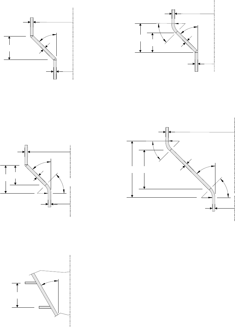
b
e
=0.55[(D
o
t)
1/2
+(D
o
t
c
/cosα)
1/2
]
L
1
α
L
c
t
t
t
c
α
L
1
L
c
L
1
t
(a) Stiffened (b) Unstiffened
C
L
t
c
Internal
Junction Ring
0.5D
c
b
e
External
Junction Ring
C
L
0.5D
o
Figure 4.4.6 – Lines of Support or Unsupported Length for Unstiffened and Stiffened Conical Shells
标准分享网 www.bzfxw.com 免费下载
2010 SECTION VIII, DIVISION 2
4-111
α
L
ce
=L
c
α
α
α
r
k
r
f
α
α
α
α
r
k
r
f
L
c
L
ce
=L
c
L
c
L
c
t
L
R
S
R
L
t
c
t
S
t
L
R
L
R
S
t
S
t
c
t
L
R
S
t
S
R
L
t
c
t
L
R
L
R
S
t
S
t
c
L
ce
L
ce
L
ce
(a) Cone without a Knuckle at Large End
without a Flare at the Small End
(b) Cone with a Knuckle at Large End
without a Flare at the Small End
(c) Cone without a Knuckle at Large End
with a Flare at the Small End
(d) Cone with a Knuckle at Large End
with a Flare at the Small End
(e) Cone with Stiffening Rings
Figure 4.4.7 – Lines of Support or Unsupported Length for Unstiffened and Stiffened Conical Shell
Transitions with or without a Knuckle

2010 SECTION VIII, DIVISION 2
4-112
4.5 Design Rules for Openings in Shells and Heads
4.5.1 Scope
The rules in paragraph 4.5 are applicable for the design of nozzles in shells and heads subjected to internal
pressure, external pressure, and external forces and moments from supplemental loads as defined in
paragraph 4.1. Configurations, including dimensions and shape, and/or loading conditions that do not satisfy
the rules of this paragraph 4.5 may be designed in accordance with Part 5.
4.5.2 Dimensions and Shape of Nozzles
4.5.2.1 Nozzles shall be circular, elliptical, or of any other shape which results from the intersection of a
circular or elliptical cylinder with vessels of the shapes for which design equations are provided in paragraphs
4.3 and 4.4. The design rules in this paragraph shall only be used if the ratio of the inside diameter of the
shell and the shell thickness is less than or equal to 400. In addition, the ratio of the diameter along the major
axis to the diameter along the minor axis of the finished nozzle opening shall be less than or equal to 1.5.
4.5.2.2 Nozzle openings that do not satisfy the criteria of paragraph 4.5.2.1 and other geometries shall
be designed in accordance with Part 5.
4.5.3 Method of Nozzle Attachment
4.5.3.1 Nozzles may be attached to the shell or head of a vessel by the following methods.
a) Welded Connections – Nozzles attachment by welding shall be in accordance with the requirements of
paragraph 4.2.2. If other details not included in this paragraph are required, the nozzle detail shall be
designed using Part 5.
b) Studded Connections – Nozzles may be made by means of studded pad type connections. The vessel
shall have a flat surface machined on the shell, or on a built-up pad, or on a properly attached plate or
fitting. Drilled holes to be tapped shall not penetrate within one-fourth of the wall thickness from the
inside surface of the vessel after deducting corrosion allowance, unless at least the minimum thickness
required as above is maintained by adding metal to the inside surface of the vessel. Where tapped
holes are provided for studs, the threads shall be full and clean and shall engage the stud for a length,
s
t
L , defined by the following equations.
[
]
1
min , 1.5
s
tstst
L
Ld= (4.5.1)
where
1
max , 0.75
st
st st
tp
S
Ld
S
⎡⎤
⎛⎞
=
⎢⎥
⎜⎟
⎜⎟
⎢⎥
⎝⎠
⎣⎦
(4.5.2)
c) Threaded Connections – Pipes, tubes, and other threaded connections that conform to the ANSI/ASME
Standard for Pipe Threads, General Purpose, Inch (ASME B1.20.1) may be screwed into a threaded
hole in a vessel wall, provided the connection size is less than or equal to DN 50 (NPS 2) and the pipe
engages the minimum number of threads specified in Table 4.5.1 after allowance has been made for
curvature of the vessel wall. The thread shall be a standard taper pipe thread except that a straight
thread of at least equal strength may be used if other sealing means to prevent leakage are provided. A
built-up pad or a properly attached plate or fitting may be used to provide the metal thickness and
number of threads required in Table 4.5.1, or to furnish reinforcement when required.
标准分享网 www.bzfxw.com 免费下载

2010 SECTION VIII, DIVISION 2
4-113
d) Expanded Connections – A pipe, tube, or forging may be attached to the wall of a vessel by inserting
through an unreinforced opening and expanding into the shell, provided the diameter is not greater than
DN 50 (NPS 2) pipe size. A pipe, tube, or forging not exceeding 150 mm (6 in.) in outside diameter may
be attached to the wall of a vessel by inserting through a reinforced opening and expanding into the
shell. The expanded connection shall be made using one of the following methods:
1) Firmly rolled in and beaded
2) Rolled in, beaded, and seal-welded around the edge of the bead
3) Expanded and flared not less than 3 mm (0.125 in.) over the diameter of the hole
4) Rolled, flared, and welded; or
5) Rolled and welded without flaring or beading, provided the ends extend at least 6 mm (0.25 in.), but
no more than 10 mm (0.375 in.), through the shell and the throat of the weld is at least 5 mm
(0.1875 in.), but no more than 8 mm (0.3125 in.).
4.5.3.2 Additional requirements for nozzle connections are as follows.
a) When the tube or pipe does not exceed 38 mm (1.5 in.) in outside diameter, the shell may be chamfered
or recessed to a depth at least equal to the thickness of the tube or pipe and the tube or pipe may be
rolled into place and welded. In no case shall the end of the tube or pipe extend more than 10 mm
(0.375 in.) beyond the inside diameter of the shell.
b) Grooving of shell openings in which tubes and pipe are to be rolled or expanded is permissible.
c) Expanded connections shall not be used as a method of attachment to vessels used for the processing
or storage of flammable and/or noxious gases and liquids unless the connections are seal-welded.
d) Reinforcing plates and saddles attached to the outside of a vessel shall be provided with at least one
vent hole that may be tapped for a preliminary compressed air and soap solution (or equivalent) test for
tightness of welds that seal off the inside of the vessel. These vent holes may be left open or may be
plugged when the vessel is in service. If the holes are plugged, the plugging material used shall not be
capable of sustaining pressure between the reinforcing plate and the vessel wall. Vent holes shall not
be plugged during heat treatment.
4.5.4 Nozzle Neck Minimum Thickness Requirements
4.5.4.1 The minimum nozzle neck thickness for nozzles excluding access openings and openings for
inspection shall be determined for internal and external pressure using paragraphs 4.3 and 4.4, as applicable.
Corrosion allowance and the effects of external forces and moments from supplemental loads shall be
considered in these calculations. The resulting nozzle neck thickness shall not be less than the smaller of the
shell thickness or the thickness given in Table 4.5.2. Corrosion allowance shall be added to the minimum
nozzle neck thickness.
4.5.4.2 The minimum nozzle neck thickness for access openings and openings for inspection shall be
determined for internal and external pressure using paragraphs 4.3 and 4.4. Corrosion allowance shall be
considered in these calculations.
4.5.5 Radial Nozzle in a Cylindrical Shell
4.5.5.1 The procedure to design a radial nozzle in a cylindrical shell subject to pressure loading is shown
below. The parameters used in this design procedure are shown in Figures 4.5.1, 4.5.2, and 4.5.3.
a) STEP 1 – Calculate the limit of reinforcement along the vessel wall:
1) For integrally reinforced nozzles:
min , 2
Reffn
LRtR
⎡
⎤
=
⎣
⎦
(4.5.3)

2010 SECTION VIII, DIVISION 2
4-114
2) For nozzles with reinforcing pads:
1Reff
LRtW=+
(4.5.4)
()
()
2Reff e
L
R ttt=++
(4.5.5)
3
2
Rn
LR= (4.5.6)
[
]
123
min , ,
RRRR
LLLL= (4.5.7)
b) STEP 2 – Calculate the limit of reinforcement along the nozzle wall projecting outside the vessel surface:
1
H
enn
Ltt Rt=+ + (4.5.8)
21
=+
Hpr
L L t for nozzles inserted throughthe vessel wall (4.5.9)
21Hpr
L L for nozzles abutting the vessel wall= (4.5.10)
()
3
8
H
e
Ltt=+ (4.5.11)
[
]
123
min , ,
HHHH
L
LLL= (4.5.12)
c) STEP 3 – Calculate the limit of reinforcement along the nozzle wall projecting inside the vessel surface,
if applicable:
1Inn
LRt= (4.5.13)
22Ipr
LL=
(4.5.14)
()
3
8
Ie
L
tt=+
(4.5.15)
[
]
123
min , ,
IIII
LLLL= (4.5.16)
d) STEP 4 – Determine the total available area near the nozzle opening (see Figure 4.5.1).
1234142435
()
Trn rp
A
AfAA A A A fA=+ + + + + +
(4.5.17)
()
0.85
1
max ,1.0
5
R
AtL
λ
⎡⎤
⎛⎞
=⋅
⎢⎥
⎜⎟
⎝⎠
⎢⎥
⎣⎦
(4.5.18)
()
()
2
min , 12.0
nn
ieffeff
Rt
Dt t
λ
⎡⎤
⎧⎫
+
⎪⎪
⎢⎥
=
⎨⎬
⎢⎥
+
⎪⎪
⎢⎥
⎩⎭
⎣⎦
(4.5.19)
标准分享网 www.bzfxw.com 免费下载
