ASME Section VIII div 2 2010. ASME Boiler and Pressure Vessel Code. Alternative Rules
Подождите немного. Документ загружается.

2010 SECTION VIII, DIVISION 2
4-75
D
t
L
r
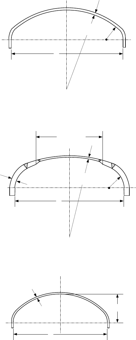
Figure 4.3.3 – Torispherical Head of Uniform Thickness
D
t
sh
L
r
0.8 D Max.
t
th
Figure 4.3.4 – Torispherical Head of Different Thickness of Dome and Knuckle
h
D
t
Figure 4.3.5 – Ellipsoidal Head
2010 SECTION VIII, DIVISION 2
4-76
t
T
t/2
R
m
weld
C
L
Reduced girth
must be on O.D.
R
m
t max.
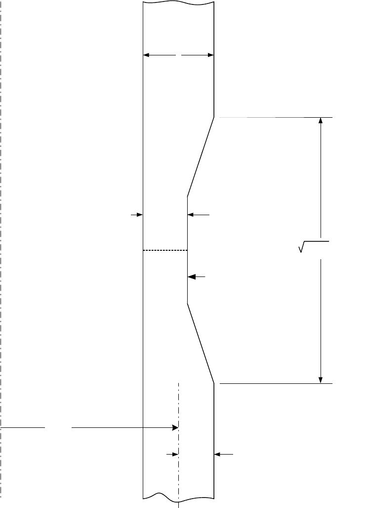
Figure 4.3.6 – Local Thin Band in a Cylindrical Shell
标准分享网 www.bzfxw.com 免费下载
2010 SECTION VIII, DIVISION 2
4-77
R
i
e
M
t
σ
θ
σ
Ζ
τ
Section Considered
M
F
(a) Stresses Within A
Cylindrical Shell
M
t
σ
Ζ
τ
Section Considered
M
F
(b) Stresses Within A
Spherical Shell
M
t
σ
θ
σ
Ζ
τ
M
F
(c) Stresses Within A
Conical Shell
φ
R
i
e
θ
σ
θ
θ
R
i
α
e
θ
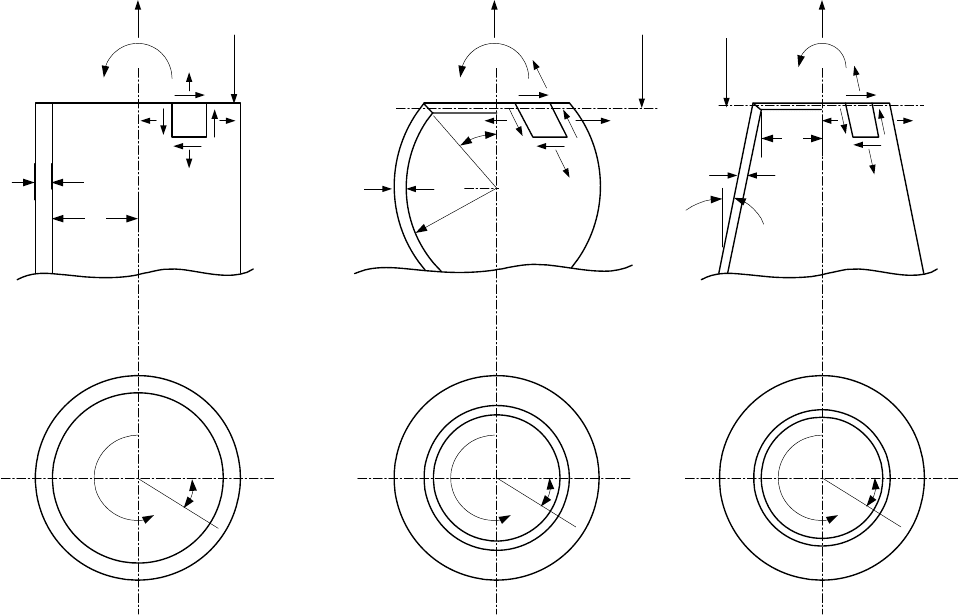
Figure 4.3.7 – Shells Subjected to Supplemental Loadings
2010 SECTION VIII, DIVISION 2
4-78
α
α
α
r
k
r
f
α
α
α
α
r
k
r
f
L
c
L
c
L
c
L
c
t
L
R
S
R
L
t
C
t
S
t
L
R
L
R
S
t
S
t
C
t
L
R
S
t
S
R
L
t
c
t
L
R
L
R
S
t
S
t
C
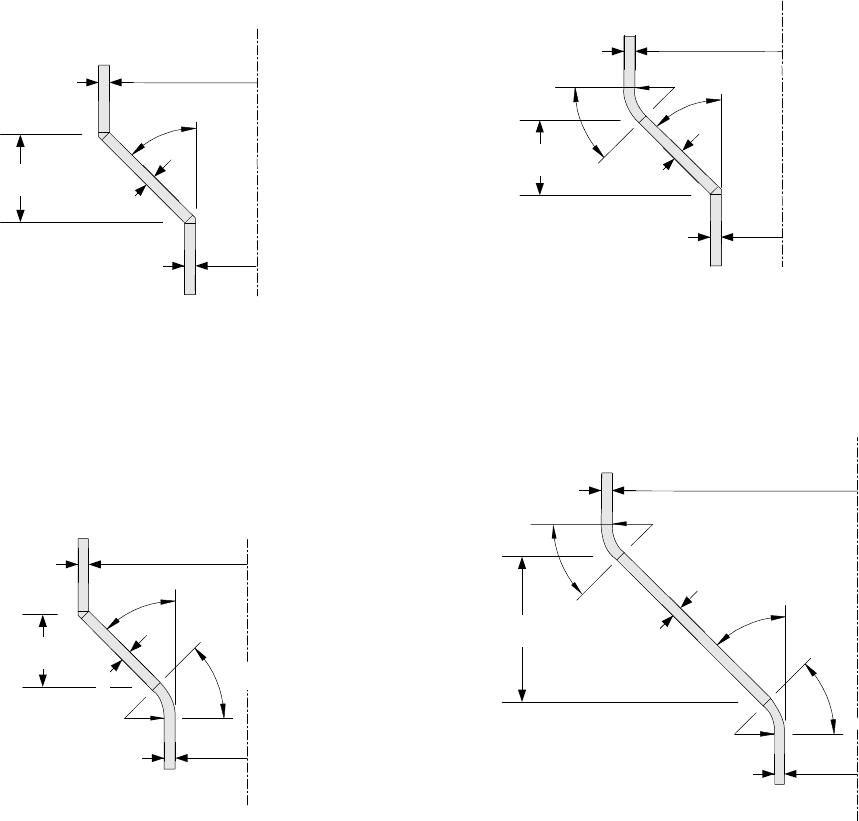
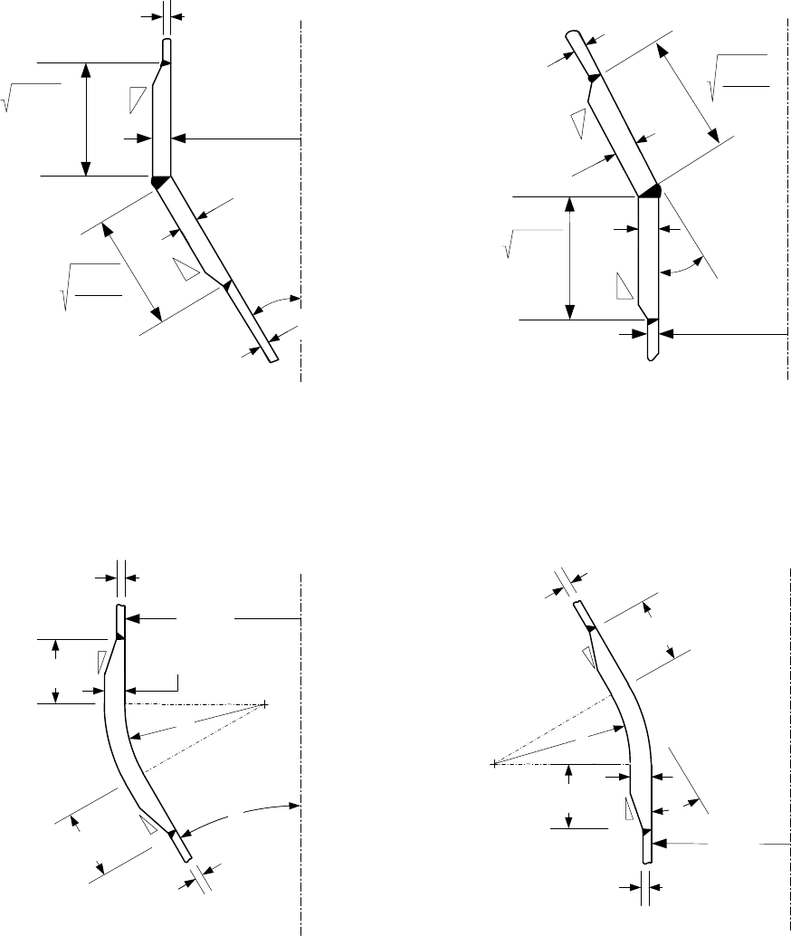
(a) Cone without a Knuckle at Large and
without a Flare at the Small End
(b) Cone with a Knuckle at Large and
without a Flare at the Small End
(c) Cone without a Knuckle at Large and
with a Flare at the Small End
(d) Cone with a Knuckle at Large and
with a Flare at the Small End
Figure 4.3.8 – Conical Transition Details
标准分享网 www.bzfxw.com 免费下载
2010 SECTION VIII, DIVISION 2
4-79
3030
C
L
1
3
t
L
1
3
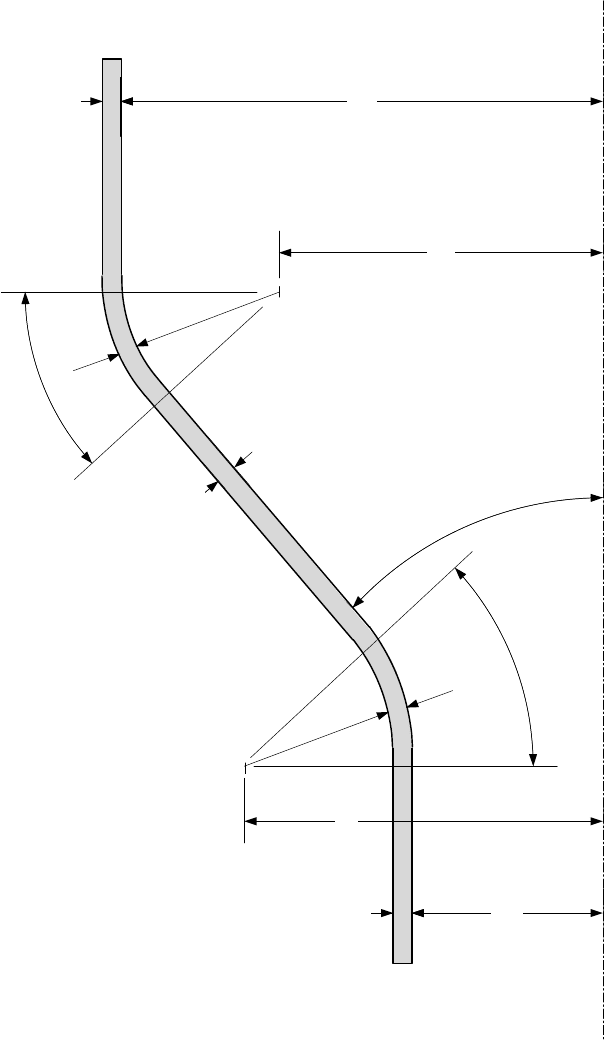
(c) Large End of Cone with Knuckle
t
j
L
K
L
K
r
K
α
R
L
t
C
C
L
2.0 R
L
t
j
1
3
t
L
α
R
L
t
j
2.0 R
L
t
j
cos
α
1
3
t
j
C
L
R
S
t
S
1.4 R
S
t
j
1
3
t
j
α
t
j
1.4 R
S
t
j
α
cos
1
3
(a) Large End of Cone
(b) Small End of Cone
t
C
t
C
C
L
R
S
(d) Small End of Cone with Flare
3030
1
3
1
3
L
f
L
f
α
t
j
r
f
t
S
t
C
Figure 4.3.9 – Reinforcement Requirements for Conical Transition Junction
2010 SECTION VIII, DIVISION 2
4-80
α
L
C
R
k
TL-1
TL-2
t
k
r
f
TL-4
TL-3
t
f
R
f
α
t
S
R
S
t
L
R
L
α
t
C
r
k
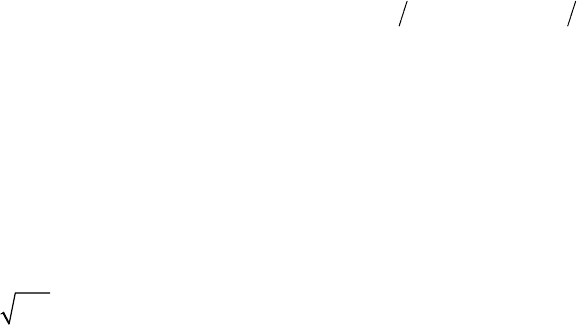
Figure 4.3.10 – Parameters for Knuckle and Flare Design
标准分享网 www.bzfxw.com 免费下载
2010 SECTION VIII, DIVISION 2
4-81
4.4 Design of Shells Under External Pressure and Allowable Compressive Stresses
4.4.1 Scope
4.4.1.1 Paragraph 4.4 provides rules for determining the required wall thickness of cylindrical, conical,
spherical, torispherical, and ellipsoidal shells and heads subject to external pressure. In this context, external
pressure is defined as pressure acting on the convex side of the shell.
4.4.1.2 The effects of supplemental loads are not included in the design equations for shells and heads
included in paragraphs 4.4.5 to 4.4.9. The effects of supplemental loads that result in combined loadings
shall be evaluated in a separate analysis performed in accordance with the methods in paragraph 4.4.12.
4.4.1.3 Rules are also provided for the design of cylindrical-to-conical shell transition junctions in
paragraphs 4.4.13 and 4.4.14. To facilitate the use of these rules, it is recommended that the shell wall
thickness and stiffener configuration, as applicable, first be designed using the rules in paragraphs 4.4.5
through 4.4.9. After an initial design is determined, this design should then be checked and modified as
required using the rules of paragraphs 4.4.13 and 4.4.14.
4.4.1.4 The equations in this paragraph are applicable for
2000
o
Dt
≤
. If 2000
o
Dt> , then the
design shall be in accordance with Part 5. In developing the equations in the paragraph, the shell section is
assumed to be axisymmetric with uniform thickness for unstiffened cylinders and formed heads. Stiffened
cylinders and cones are also assumed to be of uniform thickness between stiffeners. Where nozzles with
reinforcing plates or locally thickened shell sections exist, the thinnest uniform thickness in the applicable
unstiffened or stiffened shell section shall be used for the calculation of the allowable compressive stress.
4.4.1.5 Special consideration shall be given to ends of components (shell sections) or areas of load
application where stress distribution may be in the inelastic range and localized stresses may exceed those
predicted by linear theory.
4.4.1.6 When the localized stresses extend over a distance equal to one-half the length of the buckling
mode (approximately
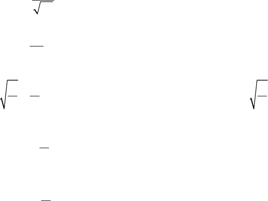
1.2
o
Dt), the localized stresses shall be considered as a uniform stress for the design
of the shell section.
4.4.1.7 The buckling strength formulations presented in this paragraph are based upon linear structural
stability theory which is modified by reduction factors which account for the effects of imperfections, boundary
conditions, non-linearity of material properties and residual stresses. The reduction factors are determined
from approximate lower bound values of test data of shells with initial imperfections representative of the
tolerance limits specified in this paragraph.
4.4.2 Design Factors
The allowable stresses are determined by applying a design factor,
FS , to the predicted buckling stresses.
The required values of
F
S
are 2.0 when the buckling stress is elastic and 1.667 when the predicted buckling
stress equals the minimum specified yield strength at the design temperature. A linear variation shall be used
between these limits. The equations for
FS are given below where
ic
F is the predicted buckling stress that
is determined by setting
1.0FS =
in the allowable stress equations. For combinations of design loads and
earthquake loading or wind loading (see paragraph 4.1.5.3), the allowable stress for
bha
F or
ba
F in Equations
(4.4.106), (4.4.107), (4.4.108), (4.4.111), (4.4.112) and (4.4.113) may be increased by a factor of 1.2.
2.0 0.55
ic y
FS for F S=≤ (4.4.1)

2010 SECTION VIII, DIVISION 2
4-82
2.407 0.741 0.55
ic
yicy
y
F
FS for S F S
S
⎛⎞
=− <<
⎜⎟
⎜⎟
⎝⎠
(4.4.2)
1.667
ic y
FS for F S== (4.4.3)
4.4.3 Material Properties
4.4.3.1 The equations for the allowable compressive stress are based on carbon and low alloy steel plate
materials as given in Part 3. The maximum temperature limit permitted for these materials is defined in Table
4.4.1. For materials other than carbon or low alloy steel, a modification to the allowable stress is required.
The procedure for modification of the allowable stress is to calculate the allowable compressive stress based
on carbon and low alloy steel plate materials, and then make the following adjustments as described below.
a) Determine the tangent modulus,
t
E , from paragraph 3.D.5 based on a stress equal to
x
e
F . For Axial
Compression the allowable stress is adjusted as follows:
x
et
xa
y
FE
F
FS E
=
(4.4.4)
ba xa
FF= (4.4.5)
b) Determine the tangent modulus,
t
E , from paragraph 3.D.5 based on a stress equal to
he
F . For External
Pressure the allowable stress is adjusted as follows:
he t
ha
y
FE
F
FS E
=
(4.4.6)
c) Determine the tangent modulus,
t
E , from paragraph 3.D.5 based on a stress equal to
ve
F . For Shear
the allowable stress is adjusted as follows:
ve t
va
y
FE
F
FS E
=
(4.4.7)
4.4.3.2 The equations for the allowable compressive stress may be used in the time-independent region
for the material of construction as provided in Table 4.4.1. If the component as designed is in the time-
dependent region (i.e. creep is significant), the effects of time-dependent behavior shall be considered.
4.4.4 Shell Tolerances
4.4.4.1 Permissible Out-Of-Roundness Of Cylindrical, Conical, and Spherical Shells – The shell of a
completed vessel subject to external pressure shall meet the following requirements at any cross section.
a) The out-of-roundness requirements in paragraph 4.3.2.1 shall be satisfied.
b) The maximum plus or minus deviation from a true circle,
e , measured from a segmental circular
template having the design inside or outside radius (depending on where the measurements are taken)
and a chord length,
ec
L , should not exceed the following value:
[
]
min , 2
c
eet= (4.4.8)
标准分享网 www.bzfxw.com 免费下载
2010 SECTION VIII, DIVISION 2
4-83
where
1.069
0.0165 3.25 0.2 0.0242
ec
c c
L
et validforteR
Rt
⎛⎞
=+ ≤≤
⎜⎟
⎝⎠
(4.4.9)
2sin
2
ec
LR
n
π
⎡⎤
=
⎢⎥
⎣⎦
(4.4.10)
21.41
R
RR
n valid for n
tL t
ψ
ξ
⎛⎞
⎛⎞
=⋅ ≤≤
⎜⎟
⎜⎟
⎜⎟
⎝⎠
⎝⎠
(4.4.11)
0.54
min 2.28 , 2.80
R
t
ξ
⎡⎤
⎛⎞
=
⎢⎥
⎜⎟
⎝⎠
⎢⎥
⎣⎦
(4.4.12)
0.044
min 0.38 , 0.485
R
t
ψ
⎡⎤
⎛⎞
=
⎢⎥
⎜⎟
⎝⎠
⎢⎥
⎣⎦
(4.4.13)
c) The value of thickness,
t , used in the above equations shall be determined as follows:
1) For vessels with butt joints,
t is the nominal plate thickness less the corrosion allowance.
2) For vessels with lap joints,
t is the nominal plate thickness and the permissible deviation is et
+
.
3) Where the shell at any cross section is made from plates of different thicknesses
t is the nominal
plate thickness of the thinnest plate less the corrosion allowance.
d) For cones and conical sections,
t shall be determined using paragraph 4.4.4.1.c except that t shall be
replaced by
c
t .
e) Measurements for out–of-tolerances shall be taken on the surface of the base metal and not on welds or
other raised parts of the component.
f) The dimensions of a completed vessel may be brought within the requirements of this paragraph by any
process that will not impair the strength of the material.
g) Sharp bends and flats spots shall not be permitted unless provision is made for them in the design or
they satisfy the tolerances in paragraphs 4.4.4.2 and 4.4.4.4.
h) Vessels fabricated of pipe may have permissible variations in the outside diameter in accordance with
those permitted under the specification covering its manufacture.
4.4.4.2 Cylindrical and Conical Shells Subject To Uniform Axial Compression and Axial Compression
Due to a Bending Moment – the tolerance requirements in paragraph 4.3.2.1 shall be satisfied. In addition,
the local inward deviation from a straight line,
e , measured along a meridian over gauge length,
x
L , shall not
exceed the maximum permissible deviation,
x
e , given below:
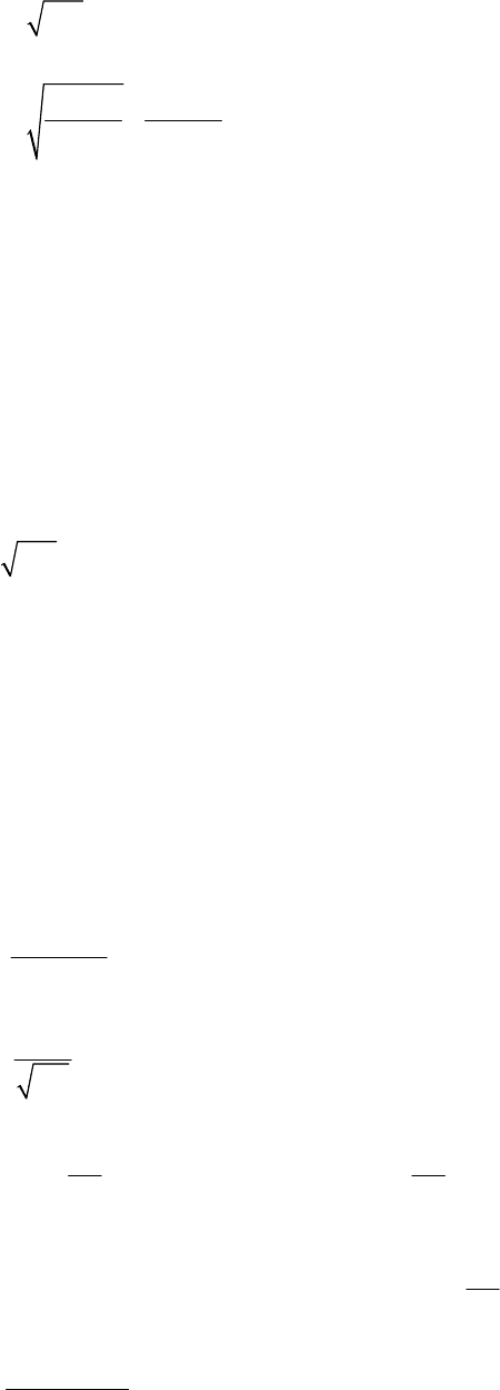
0.002
x
m
eR= (4.4.14)
and,
2010 SECTION VIII, DIVISION 2
4-84
min 4 ,
xm
L R t L for cylindrical shells
⎡⎤
=
⎣⎦
(4.4.15)
[] []
min 4 ,
cos cos
mc c
x
Rt L
L for conical shells
αα
⎡⎤
=
⎢⎥
⎢⎥
⎣⎦
(4.4.16)
25
x
L t across circumferential welds= (4.4.17)
4.4.4.3 Cylindrical and Conical Shells Subject To External Pressure And Uniform Axial Compression and
Axial Compression Due to a Bending Moment – all of the tolerance requirements in paragraphs 4.4.4.1 and
4.4.4.2 shall be satisfied.
4.4.4.4 Spherical Shells and Formed Heads – the tolerance requirements in paragraph 4.3.2.2 shall be
satisfied. In addition, the maximum local deviation from true circular form,
e , for spherical shells and any
spherical portion of a formed head shall not exceed the shell thickness. Measurements to determine the
maximum local deviation shall be made with a template with a chord length,
e
L , given by the following
equation.
3.72
em
LRt= (4.4.18)
4.4.4.5 Shells that do not meet the tolerance requirements of this paragraph may be evaluated using
paragraph 4.14.
4.4.5 Cylindrical Shell
4.4.5.1 Required Thickness – The required thickness of a cylindrical shell subjected to external pressure
loading shall be determined using the following procedure.
a) STEP 1 – Assume an initial thickness,
t , and unsupported length, L (see Figures 4.4.1 and 4.4.2).
b) STEP 2 – Calculate the predicted elastic buckling stress,
he
F .
1.6
hy
he
o
CEt
F
D
=
(4.4.19)
x
o
L
M
R
t
=
(4.4.20)
0.94
0.55 2
o
hx
o
D
t
CforM
Dt
⎛⎞
⎛⎞
=≥
⎜⎟
⎜⎟
⎝⎠
⎝⎠
(4.4.21)
0.94
1.058
1.12 13 2
o
hx x
D
CM forM
t
−
⎛⎞
=<<
⎜⎟
⎝⎠
(4.4.22)
0.92
1.5 13
0.579
hx
x
CforM
M
=<≤
−
(4.4.23)
标准分享网 www.bzfxw.com 免费下载
