ASME Section VIII div 2 2010. ASME Boiler and Pressure Vessel Code. Alternative Rules
Подождите немного. Документ загружается.

2010 SECTION VIII, DIVISION 2
4-85
1.0 1.5
hx
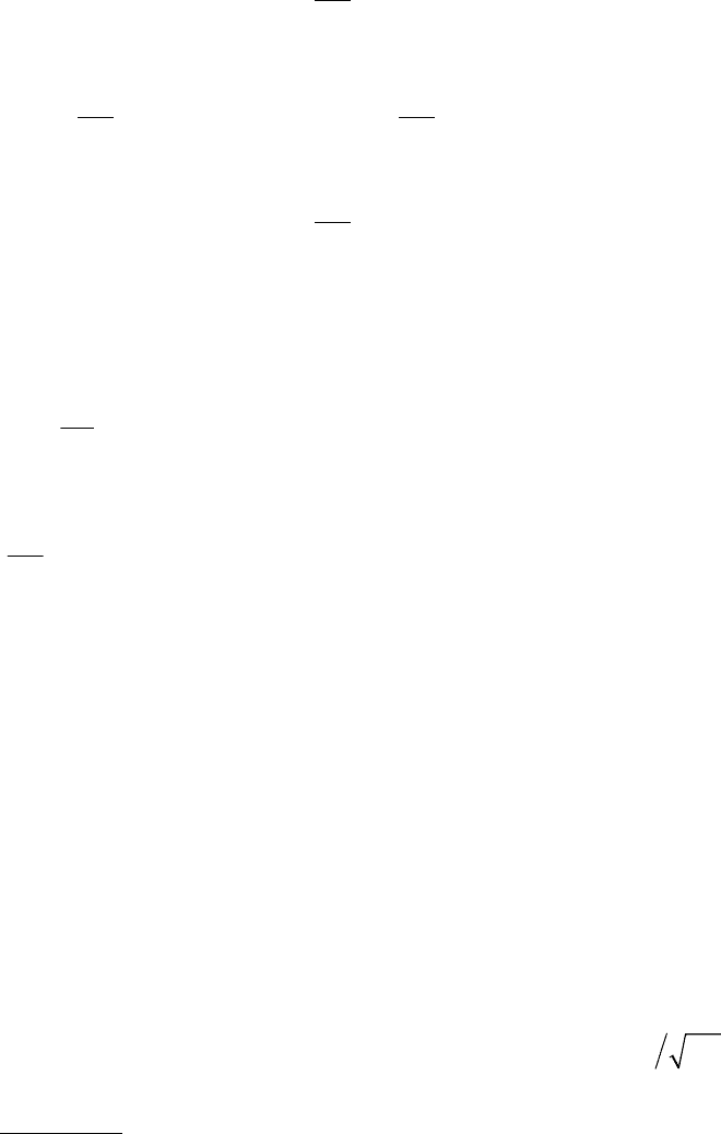
CforM=≤ (4.4.24)
c) STEP 3 – Calculate the predicted buckling stress,
ic
F .
2.439
he
ic y
y
F
FS for
S
=≥
(4.4.25)
0.4
0.7 0.552 2.439
he he
ic y
yy
FF
FS for
SS
⎛⎞
=<<
⎜⎟
⎜⎟
⎝⎠
(4.4.26)
0.552
he
ic he
y
F
FF for
S
=≤
(4.4.27)
d) STEP 4 – Calculate the value of design factor,
FS , per paragraph 4.4.2.
e) STEP 5 – Calculate the allowable external pressure,
a
P .
2
aha
o
t
PF
D
⎛⎞
=
⎜⎟
⎝⎠
(4.4.28)
where,
ic
ha
F
F
FS
=
(4.4.29)
f) STEP 6 – If the allowable external pressure,
a
P , is less than the design external pressure, increase the
shell thickness or reduce the unsupported length of the shell (i.e. by the addition of a stiffening rings) and
go to STEP 2. Repeat this process until the allowable external pressure is equal to or greater than the
design external pressure.
4.4.5.2 Stiffening Ring Size – The following equations shall be used to determine the size of a stiffening
ring.
a) Stiffening Ring Configuration – A combination of large and small stiffening rings may be used along the
length of a shell. If a single size stiffener is used, then it shall be sized as a small stiffener. Alternatively,
a combination of large and small stiffeners can be used to reduce the size of the intermittent small
stiffening rings. The large stiffening rings may be sized to function as end stiffeners or bulkheads with
small stiffeners spaced as required between end rings based on the shell thickness selected and loading
combinations considered in the design.
b) Small Stiffening Ring – The required moment of inertia of the effective stiffening ring (i.e. actual stiffening
ring plus the effective length of shell, see Figure 4.4.3) shall satisfy Equation (4.4.30). The parameter
he
F shall be evaluated using the equations in paragraph 4.4.5.1 with
x
so
M
LRt= .
()
2
2
1.5
1
C
he s c
s
y
FLRt
I
En
≥
−
(4.4.30)
where,

2010 SECTION VIII, DIVISION 2
4-86
1.5
0.5
2
;22,
3
10 10
o
B
D
n where n is an integer for n use n
Lt
and for n use n
=<=
>=
(4.4.31)
The actual moment of inertia of the composite section comprised of the small stiffening ring and effective
length of the shell about the centroidal axis shall be calculated using Equation (4.4.32):
3
2
12
C
ee
ssss
se
Lt Lt
IIAZ
ALt
⎛⎞
=+ +
⎜⎟
+
⎝⎠
(4.4.32)
where,
1.1
eo
LDt= (4.4.33)
c) Large Stiffening Ring or Bulkhead – The required moment of inertia of the effective stiffening ring (i.e.
actual stiffening ring plus the effective length of shell) shall satisfy Equation (4.4.34). The parameter
hef
F is the average value of the hoop buckling stress,
he
F , over length
F
L evaluated using the
equations in paragraph 4.4.5.1 with
x
Fo
M
LRt= .
2
2
hef F c
C
L
y
FLRt
I
E
≥
(4.4.34)
The actual moment of inertia of the composite section comprised of the large stiffening ring and effective
length of the shell about the centroidal axis shall be calculated using Equation (4.4.35):
3
2
12
C
ee
LLLL
Le
Lt Lt
IIAZ
ALt
⎛⎞
=+ +
⎜⎟
+
⎝⎠
(4.4.35)
where,
1.1
ss
eo
Ls
ALt
LDt
ALt
⎛⎞
+
=
⎜⎟
+
⎝⎠
(4.4.36)
d) Local Stiffener Geometry Requirements for all Loading Conditions – The following equations shall be
met to assure the stability of a stiffening ring.
1) Flat bar stiffener, flange of a tee section and the outstanding leg of an angle stiffener (see Figure
4.4.3)
0.5
1
1
0.375
y
y
E
h
tS
⎛⎞
≤
⎜⎟
⎜⎟
⎝⎠
(4.4.37)
2) Web of a tee stiffener or leg of an angle stiffener attached to the shell (see Figure 4.4.3).
0.5
2
2
y
y
E
h
tS
⎛⎞
≤
⎜⎟
⎜⎟
⎝⎠
(4.4.38)
标准分享网 www.bzfxw.com 免费下载

2010 SECTION VIII, DIVISION 2
4-87
e) Stiffener Size To Increase Allowable Longitudinal Compressive Stress – ring stiffeners can be used to
increase the allowable longitudinal compressive stress for cylindrical or conical shells subject to uniform
axial compression and axial compression due to bending. The required size of the stiffener shall satisfy
the following equations. In addition, the spacing of the stiffeners must result in a value of
15
s
M
≤
where
s
M
is given by Equation (4.4.42).
0.6
0.334
0.063
s
s
s
ALt
M
⎛⎞
≥−
⎜⎟
⎝⎠
(4.4.39)
0.06
s
s
ALt≥ (4.4.40)
3
1.8
5.33
C
s
s
s
Lt
I
M
≥
(4.4.41)
s
s
o
L
M
R
t
=
(4.4.42)
f) Stiffener Size For Shear – The required size of the stiffener shall satisfy the following equation where
v
C
is evaluated using Equations (4.4.81) thru (4.4.84) with
x
s
M
M
=
,
s
M
is given by Equation (4.4.42).
0.8 3
0.184
C
s
vs s
I
CM tL≥ (4.4.43)
g) Arrangement Of Stiffening Rings
1) As shown in Figure 4.4.4, any joints between the ends or sections of such rings, at locations (A) and
(B), and any connection between adjacent portions of a stiffening ring lying inside or outside the
shell, at location (C), shall be made so that the required moment of inertia of the combined ring-
shell section is maintained. For a section with a strut at location (D), the required moment of inertia
shall be supplied by the strut alone.
2) As shown in Figure 4.4.4, stiffening rings placed on the inside of a vessel may be arranged as
shown at locations (E) and (F) provided that the required moment of inertia of the ring at location (E)
or of the combined ring-shell section at location (F) is maintained within the sections indicated.
Where the gap at locations (A) or (E) does not exceed eight times the thickness of the shell plate,
the combined moment of inertia of the shell and stiffener may be used.
3) Stiffening rings shall extend completely around the vessel except as provided below.
Any gap in
that portion of a stiffening ring supporting the shell, as shown in Figure 4.4.4 at locations (D) and
(E), shall not exceed the length of arc given in Figure 4.4.5 unless additional reinforcement is
provided as shown at location (C), or unless all of the following conditions are met:
i) only one unsupported shell arc is permitted per ring
ii) the length of unsupported shell arc does not exceed 90 deg
iii) the unsupported shell arcs in adjacent stiffening rings are staggered 180 deg
iv) the dimension
L
is taken as the larger of the distance between alternate stiffening rings or
the distance from the head-bend line to the second stiffening ring plus one-third of the head
depth

2010 SECTION VIII, DIVISION 2
4-88
4) When internal plane structures perpendicular to the longitudinal axis of the cylinder, such as bubble
trays or baffle plates, are used in a vessel, they may also be considered to act as stiffening rings
provided they are designed to function as such.
5) Any internal stays or supports used shall bear against the shell of the vessel through the medium of
a substantially continuous ring.
h) Attachment Of Stiffening Rings – Stiffening rings shall be attached to either the outside or the inside of
the vessel by continuous welding, or if the component is not in cyclic service (i.e. a fatigue analysis is not
required in accordance with paragraph 4.1.1.4) intermittent welding. Where gaps occur in the stiffening
ring, the attachment weld shall conform to the details in paragraph 4.2.
4.4.5.3 Combined Loadings – cylindrical shells subject to external pressure and other loadings shall
satisfy the requirements of paragraph 4.4.12.
4.4.6 Conical Shell
4.4.6.1 Required Thickness – The required thickness of a conical shell subjected to external pressure
loading shall be determined using the equations for a cylinder by making the following substitutions:
a) The value of
c
t is substituted for t in the equations in paragraph 4.4.5.
b) For offset cones, the cone angle,
α
, shall satisfy the requirements of paragraph 4.3.4.
c) The value of
()
[
]
0.5 cos
LS
DD
α
+ is substituted for
o
D in the equations in paragraph 4.4.5.
d) The value of
[
]
cos
ce
L
α
is substituted for L in the equations in paragraph 4.4.5 where
ce
L is
determined as shown below.
1) For Sketches (a) and (e) in Figure 4.4.7
ce c
LL= (4.4.44)
2) For Sketch (b) in Figure 4.4.7
[
]
sin
ce k c
Lr L
α
=+ (4.4.45)
3) For Sketch (c) in Figure 4.4.7
[
]
sin
ce f c
Lr L
α
=+ (4.4.46)
4) For Sketch (d) in Figure 4.4.7
()
[
]
sin
ce k f c
Lrr L
α
=+ + (4.4.47)
e) Note that the half-apex angle of a conical transition can be computed knowing the shell geometry with
the following equations. These equations were developed with the assumption that the conical transition
contains a cone section, knuckle, or flare. If the transition does not contain a knuckle or flare, the radii of
these components should be set to zero when computing the half-apex angle (see Figure 4.4.7).
1) If
()( )
Lk S f
R
rRr−≥ +
:
α
βφ
=+ (4.4.48)
标准分享网 www.bzfxw.com 免费下载

2010 SECTION VIII, DIVISION 2
4-89
()( )
arctan
Lk S f
ce
R
rRr
L
β
−− +
⎡⎤
=
⎢⎥
⎣⎦
(4.4.49)
2) If
()( )
Lk S f
R
rRr−< +:
α
φβ
=− (4.4.50)
()
(
)
arctan
Sf Lk
ce
R
rRr
L
β
⎡⎤
+− −
⎢⎥
=
⎢⎥
⎣⎦
(4.4.51)
3) In both cases shown above, the angle
φ
is given by the following equation.
()cos
arcsin
fk
ce
rr
L
β
φ
+
⎡⎤
=
⎢⎥
⎣⎦
(4.4.52)
4.4.6.2 Small Stiffening Rings – Intermediate circumferential stiffening rings within the conical transition
shall be sized using Equation (4.4.30) where
s
L is determined from paragraph 4.4.6.1.d, and
c
t is the cone
thickness at the ring location.
4.4.6.3 Combined Loadings – conical shells subject to external pressure and other loadings shall satisfy
the requirements of paragraph 4.4.12.
4.4.7 Spherical Shell and Hemispherical Head
4.4.7.1 Required Thickness – The required thickness of a spherical shell or hemispherical head
subjected to external pressure loading shall be determined using the following procedure.
a) STEP 1 – Assume an initial thickness,
t for the spherical shell.
b) STEP 2 – Calculate the predicted elastic buckling stress,
he
F .
0.075
he y
o
t
FE
R
⎛⎞
=
⎜⎟
⎝⎠
(4.4.53)
c) STEP 3 – Calculate the predicted buckling stress,
ic
F .
6.25
he
ic y
y
F
FS for
S
=≥
(4.4.54)
1.31
1.6 6.25
1.15
y
he
ic
y
y
he
S
F
Ffor
S
S
F
=<<
⎛⎞
+
⎜⎟
⎝⎠
(4.4.55)
0.18 0.45 0.55 1.6
he
ic he y
y
F
FFS for
S
=+ <≤
(4.4.56)

2010 SECTION VIII, DIVISION 2
4-90
0.55
he
ic he
y
F
FF for
S
=≤
(4.4.57)
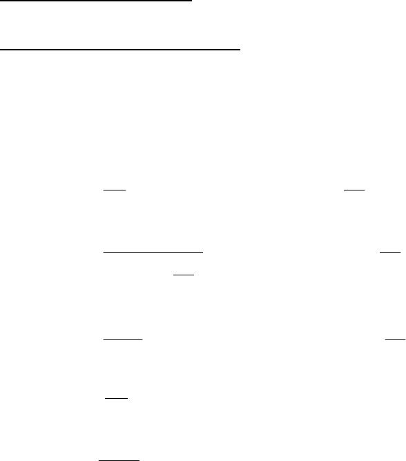
d) STEP 4 – Calculate the value of design margin,
F
S , per paragraph 4.4.2.
e) STEP 5 – Calculate the allowable external pressure,
a
P
2
aha
o
t
PF
R
⎛⎞
=
⎜⎟
⎝⎠
(4.4.58)
where,
ic
ha
F
F
FS
=
(4.4.59)
f) STEP 6 – If the allowable external pressure,
a
P , is less than the design external pressure, increase the
shell thickness and go to STEP 2. Repeat this process until the allowable external pressure is equal to
or greater than the design external pressure.
4.4.7.2 Combined Loadings – spherical shells and hemispherical heads subject to external pressure and
other loadings shall satisfy the requirements of paragraph 4.4.12.
4.4.8 Torispherical Head
4.4.8.1 Required Thickness – the required thickness of a torispherical head subjected to external
pressure loading shall be determined using the equations for a spherical shell in paragraph 4.4.7 by
substituting the outside crown radius for
o
R
.
4.4.8.2 Restrictions On Torispherical Head Geometry – the restriction of paragraph 4.3.6 shall apply.
4.4.8.3 Torispherical Heads With Different Dome and Knuckle Thicknesses – heads with this
configuration shall be designed in accordance with Part 5.
4.4.8.4 Combined Loadings – torispherical heads subject to external pressure and other loadings shall
satisfy the requirements of paragraph 4.4.12.
4.4.9 Ellipsoidal Head
4.4.9.1 Required Thickness – the required thickness of an elliptical head subjected to external pressure
loading shall be determined using the equations for a spherical shell in paragraph 4.4.7 by substituting
oo
KD
for
o
R
where
o
K is given by the following equation:
23
0.25346 0.13995 0.12238 0.015297
22 2
⎛⎞ ⎛⎞ ⎛⎞
=+ + −
⎜⎟ ⎜⎟ ⎜⎟
⎝⎠ ⎝⎠ ⎝⎠
oo o
o
oo o
DD D
K
hh h
(4.4.60)
4.4.9.2 Combined Loadings – ellipsoidal heads subject to external pressure and other loadings shall
satisfy the requirements of paragraph 4.4.12.
标准分享网 www.bzfxw.com 免费下载
2010 SECTION VIII, DIVISION 2
4-91
4.4.10 Local Thin Areas
Rules for the evaluation of Local Thin Areas are covered in paragraph 4.14.
4.4.11 Drilled Holes Not Penetrating Through the Vessel Wall
Design requirements for partially drilled holes that do not penetrate completely through the vessel wall are
covered in paragraph 4.3.9.
4.4.12 Combined Loadings and Allowable Compressive Stresses
4.4.12.1 The rules in paragraphs 4.4.2 through 4.4.11 are applicable for external pressure loading. The
rules in this paragraph provide allowable compressive stresses that shall be used for the design of shells
subjected to supplemental loads that result in combined loadings. The allowable stresses of this paragraph
shall also be used as the acceptance criteria for shells subjected to compressive stress evaluated using Part
5.
4.4.12.2 Cylindrical Shells – The allowable compressive stresses for cylindrical shells shall be computed
using the following rules that are based on loading conditions. The loading conditions are underlined for
clarity in the following paragraphs. Common parameters used in each of the loading conditions are given in
paragraph 4.4.12.2.k.
a) External Pressure Acting Alone
– the allowable hoop compressive membrane stress of a cylinder subject
to external pressure acting alone,
ha
F , is computed using the equations in paragraph 4.4.5.1.
b) Axial Compressive Stress Acting Alone
– the allowable axial compressive membrane stress of a cylinder
subject to an axial compressive load acting alone,
x
a
F , is computed using the following equations.
1) For
0.15
c
λ
≤ (Local Buckling):
[
]
12
min ,
xa xa xa
FFF= (4.4.61)
1
135
y
o
xa
S
D
Ffor
FS t
=≤
(4.4.62)
1
466
135 600
331
y
o
xa
o
S
D
Ffor
D
t
FS
t
=<<
⎛⎞
+
⎜⎟
⎝⎠
(4.4.63)
1
0.5
600 2000
y
o
xa
S
D
Ffor
FS t
=≤≤
(4.4.64)
2
x
e
xa
F
F
FS
=
(4.4.65)
x
y
xe
o
CEt
F
D
=
(4.4.66)
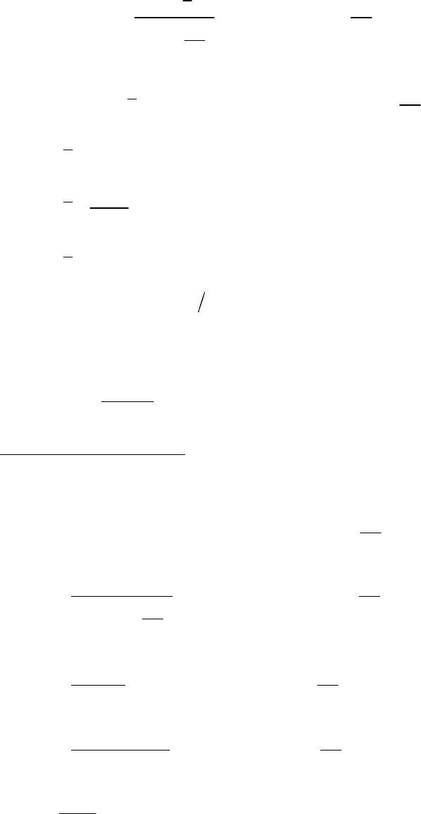
2010 SECTION VIII, DIVISION 2
4-92
409
min , 0.9 1247
389
o
x
o
D
c
Cfor
D
t
t
⎡⎤
⎢⎥
⎢⎥
=<
⎛⎞
⎢⎥
+
⎜⎟
⎢⎥
⎝⎠
⎣⎦
(4.4.67)
0.25 1247 2000
o
x
D
Cc for
t
=≤≤
(4.4.68)
2.64 1.5
x
cforM=≤ (4.4.69)
0.42
3.13
1.5 15
x
x
cforM
M
=<< (4.4.70)
1.0 15
x
cforM=≥ (4.4.71)
2) For
0.15 200
cuug
and K L r
λ
>< (Column Buckling):
()
0.3
1 0.74 0.15 0.15 1.147
ca xa c c
FF for
λλ
=− − <<⎡⎤
⎣⎦
(4.4.72)
2
0.88
1.147
xa
ca c
c
F
Ffor
λ
λ
=≥ (4.4.73)
c) Compressive Bending Stress
– the allowable axial compressive membrane stress of a cylindrical shell
subject to a bending moment acting across the full circular cross section
ba
F , is computed using the
following equations.
135 2000=≤≤
o
ba xa
D
FF for
t
(4.4.74)
466
100 135
331
y
o
ba
o
S
D
Ffor
D
t
FS
t
=≤<
⎛⎞
+
⎜⎟
⎝⎠
(4.4.75)
1.081
100 0.11
y
o
ba
S
D
F for and
FS t
γ
=<≥ (4.4.76)
()
1.4 2.9
100 0.11
y
o
ba
S
D
F for and
FS t
γ
γ
−
=<<
(4.4.77)
yo
y
SD
Et
γ
= (4.4.78)
标准分享网 www.bzfxw.com 免费下载
2010 SECTION VIII, DIVISION 2
4-93
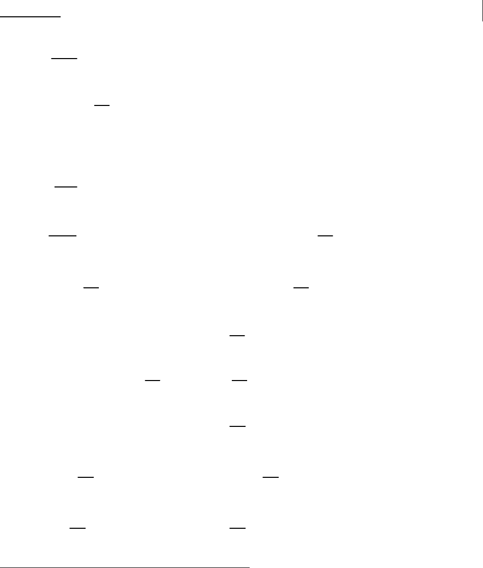
d) Shear Stress
– the allowable shear stress of a cylindrical shell ,
va
F , is computed using the following
equations.
vve
va
F
F
FS
η
= (4.4.79)
ve v v y
o
t
FCE
D
α
⎛⎞
=
⎜⎟
⎝⎠
(4.4.80)
4.454 1.5
vx
CforM=≤ (4.4.81)
()
0.5
3
2
9.64
1 0.0239 1.5 26
vxx
x
CMforM
M
⎛⎞
=+ <<
⎜⎟
⎝⎠
(4.4.82)
0.5
1.492
26 4.347
o
v x
x
D
CforM
M
t
⎛⎞
=≤<
⎜⎟
⎝⎠
(4.4.83)
0.5
0.716 4.347
o
vx
o
D
t
CforM
Dt
⎛⎞
⎛⎞
=≥
⎜⎟
⎜⎟
⎝⎠
⎝⎠
(4.4.84)
0.8 500
o
v
D
for
t
α
=≤ (4.4.85)
10
1.389 0.218log 500
oo
v
DD
for
tt
α
⎛⎞
=− >
⎜⎟
⎝⎠
(4.4.86)
1.0 0.48
ve
v
y
F
for
S
η
=≤ (4.4.87)
0.43 0.1 0.48 1.7
y
ve
v
ve y
S
F
for
FS
η
⎛⎞
=+ <<
⎜⎟
⎝⎠
(4.4.88)
0.6 1.7
y
ve
v
ve y
S
F
for
FS
η
⎛⎞
=≥
⎜⎟
⎝⎠
(4.4.89)
e) Axial Compressive Stress And Hoop Compression
– the allowable compressive stress for the
combination of uniform axial compression and hoop compression,
x
ha
F , is computed using the following
equations:
1) For
0.15
c
λ
≤ ;
x
ha
F is computed using the following equation with
ha
F and
x
a
F evaluated using the
equations in paragraphs 4.4.12.2.a and 4.4.12.2.b.1, respectively.
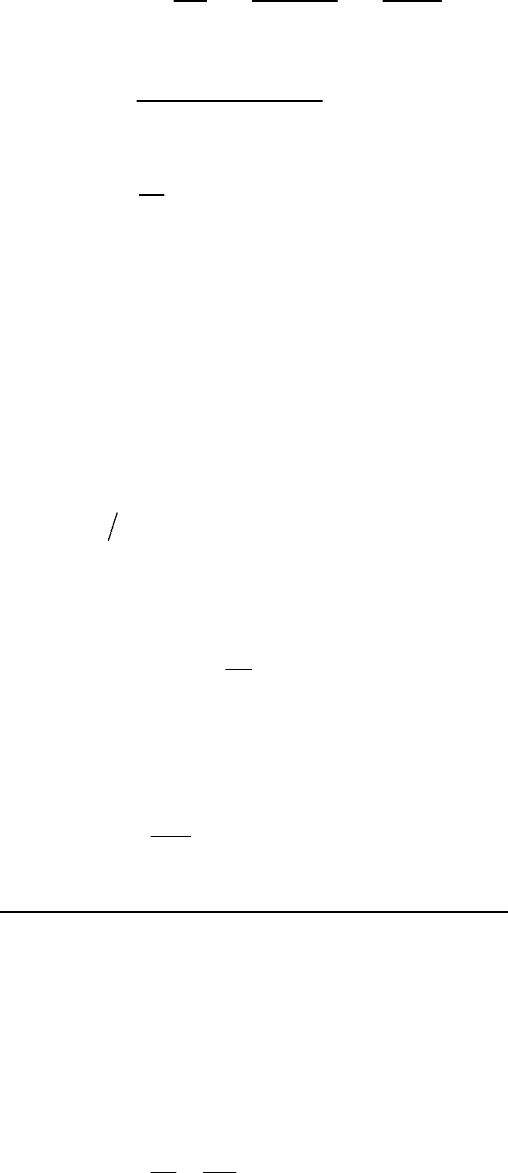
2010 SECTION VIII, DIVISION 2
4-94
0.5
1
222
22
11
xha
xa xa ha ha
C
F
FCFFCF
−
⎡⎤
⎛⎞⎛ ⎞⎛ ⎞
=− +
⎢⎥
⎜⎟⎜ ⎟⎜ ⎟
⎝⎠⎝ ⎠⎝ ⎠
⎣⎦
(4.4.90)
()
1
1.0
xa ha
y
FFSFFS
C
S
⋅+⋅
=−
(4.4.91)
2
x
h
f
C
f
=
(4.4.92)
x
aq x xha
f
ff forfF=+ ≤ (4.4.93)
The parameters
a
f
and
q
f
are defined in paragraph 4.4.12.2.k.
2) For
0.15 1.2
c
λ
<≤ :
x
ha
F is computed from the following equation with
1ah xha
FF= evaluated using
the equations in paragraph 4.4.12.2.e.1 with
x
a
f
f
=
, and
ca
F evaluated using the equations in
paragraph 4.4.12.2.b.2. As noted, the load on the end of a cylinder due to external pressure does
not contribute to column buckling and therefore
1ah
F is compared with
a
f
rather than
x
f
. The
stress due to the pressure load does, however, lower the effective yield stress and the quantity in
()
1
qy
f
S−
accounts for this reduction
[
]
12
min ,
xha ah ah
FFF= (4.4.94)
2
1
q
ah ca
y
f
FF
S
⎛⎞
=−
⎜⎟
⎜⎟
⎝⎠
(4.4.95)
3) For
0.15
c
λ
≤ , the allowable hoop compressive membrane stress,
hxa
F , is given by the following
equation:
2
x
ha
hxa
F
F
C
=
(4.4.96)
f) Compressive Bending Stress And Hoop Compression
– the allowable compressive stress for the
combination of axial compression due to a bending moment and hoop compression,
bha
F , is computed
using the following equations.
1) An iterative solution procedure is utilized to solve these equations for
C
3
with
ha
F and
ba
F evaluated using the equations in paragraphs 4.4.12.2.a and 4.4.12.2.c, respectively.
34bha ba
FCCF= (4.4.97)
4
bha
hba
f
F
C
f
F
⎛⎞⎛ ⎞
=
⎜⎟⎜ ⎟
⎝⎠⎝ ⎠
(4.4.98)
标准分享网 www.bzfxw.com 免费下载
