ASM Metals HandBook Vol. 8 - Mechanical Testing and Evaluation
Подождите немного. Документ загружается.

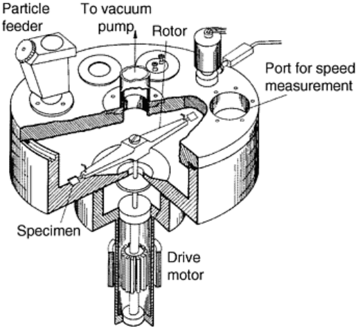
Fig. 10 Schematic diagram of whirling arm erosion rig, in which particles are dropped into the path of
two specimens attached to the ends of a rapidly rotating arm. Adapted from Ref 18
Both electric motors and air turbines have been used to rotate the specimen arm, and specimen speeds up to at
least 550 m/s have been achieved. The impact velocity can be accurately calculated from the rotor radius and
the rotational speed, while the impact angle can be controlled by fixing the specimens to the rotor arm at an
appropriate angle. This often involves the use of different rotors for different impact angles. The fate of erodent
particles after striking the specimen must be considered since they will rebound and may cause secondary
impacts, from intact particles or fragments, during subsequent rotation of the arm. Some method of capturing
the particles after impact is required. The design described in Ref 18 used sheet metal traps coated with silicone
oil to catch small dust fragments as well as whole particles.
The whirling arm method involves greater effort in specimen preparation and in conducting the test than other
methods; the time taken to load and unload the specimens, and to pump the chamber down if it is an evacuated
rig, may be significant. The specimens must be of accurate dimensions, form a dynamically balanced pair on
the whirling arm, and be sufficiently strong and tough to withstand the high centrifugal stresses imposed during
testing. These requirements have tended to restrict the method to metallic samples. Despite these
considerations, the whirling arm method can achieve the highest particle velocities, and in order to obtain
erosion data under such conditions, it has great value.
References cited in this section
7. “Standard Test Method for Conducting Erosion Tests by Solid Particle Impingement Using Gas Jets,” G
76, Annual Book of ASTM Standards, ASTM
8. G.L. Sheldon, J. Maji, and C.T. Crowe, Erosion of a Tube by Gas-Particle Flow, J. Eng. Mater.
Technol. (Trans. ASME), Vol 99, 1977, p 138–142
9. D.B. Marshall et al., Paticle Size Distribution Effects on the Solid Particle Erosion of Brittle Materials,
Wear, Vol 71, 1981, p 363–373
10. D.R. Andrews, S.M. Walley, and J.E. Field, Solid Particle Erosion Studies in the Cavendish Laboratory,
Paper 36, Proc. 6th Int. Conf. on Erosion by Liquid and Solid Impact, Cavendish Laboratory,
Cambridge, UK, 1983
11. P.H. Shipway and I.M. Hutchings, Influence of Nozzle Roughness on Conditions in a Gas-Blast Erosion
Rig, Wear, Vol 162–164, 1993, p 148–158
12. A.N.J. Stevenson and I.M. Hutchings, Scaling Laws for Particle Velocity in the Gas-Blast Erosion Test,
Wear, Vol 181–183, 1995, p 56–62
13. A.J. Burnett, S.R. De Silva, and A.R. Reed, Comparisons between Sand Blast and Centripetal Effect
Accelerator Type Erosion Testers, Wear, Vol 186–187, 1995, p 168–178
14. I.R. Kleis and K.K. Uuemyis, Mechanical Rigs for Studying Abrasive Erosion, Russ. Eng. J., Vol 51,
1971, p 13–15
15. S. Söderberg, S. Hogmark, U. Engman, and H. Swahn, Erosion Classification of Materials Using a
Centrifugal Erosion Tester, Tribol. Int., Dec 1981, p 333–343
16. W. Tabakoff, Experimental Study on the Effects of Specimen Sizes on Erosion, Wear, Vol 86, 1983, p
65–72
17. W. Tabakoff, M.F. Malak, and A. Hamed, AIAA J., Vol 25, 1987, p 721–726
18. J.E. Goodwin, W. Sage, and G.P. Tilly, Study of Erosion by Solid Particles, Proc. Inst. Mech. Eng., Vol
184, 1969, p 279–291
Solid Particle Erosive Wear Testing
Ian M. Hutchings, University of Cambridge (England)
Measurement of Particle Velocity
Since impact velocity is a very important variable in erosion, accurate measurement of impact velocity is
essential in any quantitative erosion test.
Various methods of velocity measurement have been employed. Potentially, the most accurate is laser Doppler
velocimetry (LDV), which can provide statistical information on particle speed and direction of motion at any
selected point close to, or distant from, the specimen surface. Laser Doppler velocimetry has been applied to
gas-blast, centrifugal accelerator, and wind tunnel tests (Ref 17, 19), but the apparatus can be bulky and
expensive, and for many purposes simpler methods are adequate.
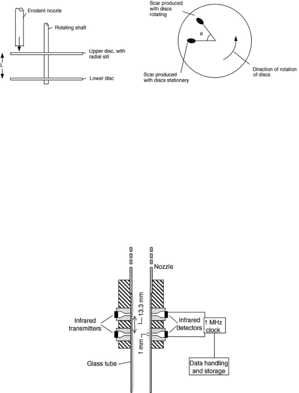
An early method, still valuable and widely used, is the rotating double-disk method (Ref 20) illustrated in Fig.
11. Two disks are rotated on a common shaft, and the stream of erodent particles is arranged to strike the upper
disk, which has a thin radial slot cut in it. The lower disk is coated with a thin paint or dye film to show where
particles strike it. Two erosion scars are formed: one with the disks stationary, with the particles passing
through the slit in the upper disk, and the other with the disks rotating at a known speed. The angular
displacement, θ, between the two scars is measured and can be used to calculate the time taken for the particles
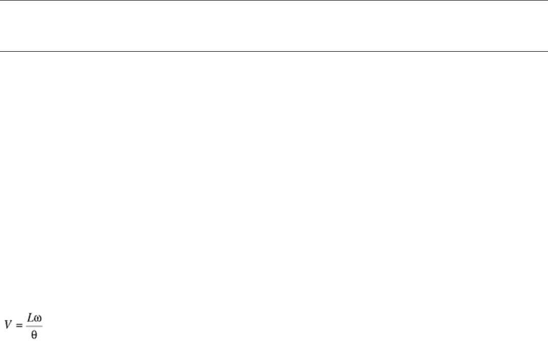
to travel the distance, L, between the disks, and hence their velocity, V. The velocity is given by:
(Eq 4)
where ω is the angular velocity of the rotating disks. In practical examples of this device, a high rotational
speed is needed to achieve reasonable displacement of the scars and thus accuracy of measurement of the angle,
θ. Values between 3000 and 10,000 revolutions per minute (rpm) are common, with a distance, L, of about 20
to 40 mm (0.8 to 1.6 in.). The method is well suited to use in an air-blast erosion test, since velocity calibration
can be carried out under exactly the same conditions of particle feed rate and air pressure as used in the erosion
test. Typically, the random error in measuring velocity in this way is ±10%. There can also be a systematic
error due to the aerodynamic influence of the rotating disks on particle stream, which may be 10% or even
greater for very small particles of low density. A comparison of velocities measured by both the double-disk
method and LDV suggests that for a typical velocity in a gas-blast rig (45 m/s) and for rather small particles (50
μm silicon carbide or alumina), the double-disk method systematically underestimates the velocity by some
10%, although the error would be expected to be less for larger particles (Ref 19).
Fig. 11 Rotating disk method for measuring particle velocity. Adapted from Ref 20
Another relatively simple method, which is well suited to use with the gas-blast method, involves measuring the
time of flight of the particles between two transverse light beams a short distance apart (Ref 11, 21). In one
version of this method, illustrated in Fig. 12, the sensor contains a short glass tube that can be attached to the
end of the nozzle; the small increase in length has been shown to have a negligible effect on the particle exit
velocity (Ref 11). The timer uses infrared emitters and detectors, and the beams are collimated by two pairs of
holes 1 mm (0.04 in.) in diameter, aligned perpendicularly to the axis of the nozzle. The electronic timing
system contains a clock that is triggered by a decrease in light intensity of approximately 0.5%. The velocity is
determined from the time taken for the particle to pass between the two beams. Inevitably, there will be some
particles that will interrupt one beam but not the other, while in some cases, the particle that stops the clock
may not be the one that started it. It can be shown by computer simulation of the system that even for a stream
of particles all traveling with the same velocity, these effects will lead to a distribution of recorded flight times.
However, in all cases, the peak in the distribution corresponds to the true flight time, from which the particle
velocity can be calculated. The use of a low concentration of particles in the gas stream helps to provide a well-
defined peak in the time distribution. Figure 13 shows typical data from this method, for spherical glass
Ballotini particles, about 130 μm in diameter, accelerated along a straight nozzle at two different driving
pressures. In this plot the times of flight have been converted into equivalent velocities over the timing distance.
Fig. 12 Optoelectronic method of determining particle velocity, by time-of-flight measurement. Source:
Ref 11
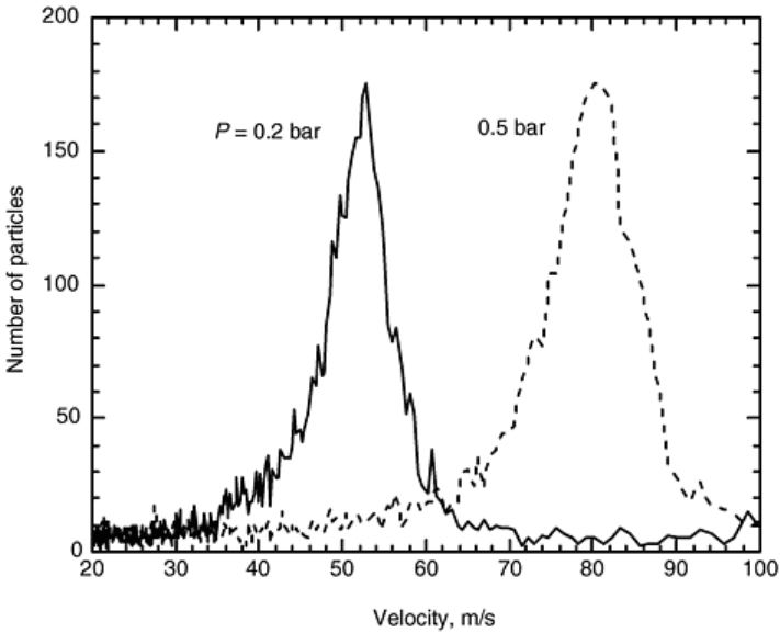
Fig. 13 Typical data from the time-of-flight method shown in Fig. 12, for 125–150 μm glass Ballotini
accelerated in a gas blast rig at nozzle pressure (P) of 0.2 and 0.5 bar. Source: Ref 11
High-speed multiple-flash photography has also been successfully used to measure particle velocities and can
provide a more economical alternative to LDV. Specialist equipment is needed to produce flashes of
sufficiently short duration to freeze the motion of rapidly moving particles, with accurately known interflash
timing. To image the small particles used in erosion testing, a relatively small field of view is needed, with
sharp focus and a small depth of field. Conventional stroboscopic light sources tend to be too slow to be useful
and of insufficient brightness when used at the high speeds that are needed; a means of triggering separate
short-duration flash sources at precise time intervals provides a better method. Although two flashes alone are
sufficient in principle to determine a velocity, confusion can occur in identifying which images correspond to
each particle if there are several images in the frame, and a sequence of several flashes can provide more
reliable data. Figure 14 illustrates this method and shows images of olivine sand particles leaving a horizontal
gas-blast nozzle at a mean speed of 30 m/s, produced with a four-flash sequence. The image was captured with
a video camera and computer frame-grabber card synchronized with the flashes. This method provides very
quick image acquisition, and since the image is already in digital form, particle velocity vectors can easily and
quickly be determined by suitable image analysis software.
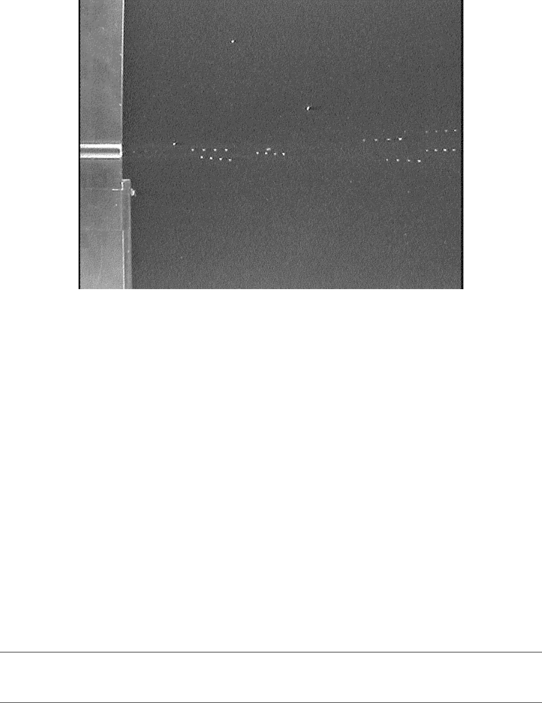
Fig. 14 Multiple flash image showing olivine sand particles leaving a horizontal gas-blast nozzle (at the
left of the frame) and traveling to the right at a mean velocity of 30 ms. The particles were imaged with
four short duration flashes at 0.2 ms intervals, and the frame was acquired with a video camera and
computer image-grabber card. Courtesy of D.N. Allsopp and I.M. Hutchings, University of Cambridge,
UK
References cited in this section
11. P.H. Shipway and I.M. Hutchings, Influence of Nozzle Roughness on Conditions in a Gas-Blast Erosion
Rig, Wear, Vol 162–164, 1993, p 148–158
17. W. Tabakoff, M.F. Malak, and A. Hamed, AIAA J., Vol 25, 1987, p 721–726
19. V. Ponnaganti, D.E. Stock, and G.L. Sheldon, Measurement of Particle Velocities in Erosion Processes,
Polyphase Flow and Transport Technology, R.A. Bajura, Ed., ASME, 1980, p 217–222
20. A.W. Ruff and L.K. Ives, Measurement of Solid Particle Velocity in Erosive Wear, Wear, Vol 35, 1975,
p 195–199
21. T.H. Kosel and K. Anand, An Optoelectronic Erodent Particle Velocimeter, Corrosion and Particle
Erosion at High Temperatures, V. Srinivasan and K. Vedula, Ed., The Minerals, Metals and Materials
Society, 1989, p 349–368
Solid Particle Erosive Wear Testing
Ian M. Hutchings, University of Cambridge (England)
Data Analysis and Interpretation
Most erosion tests are performed to determine the rate of material removal, and the primary measurement of
material loss is by weighing. Since the mass loss to be measured will usually be small, often less than 1 mg, it is
very important that the balance used to weigh the specimen has adequate sensitivity and long-term stability.
The latter point is important, since an erosion experiment may last for several hours or even days, and the
measurement involves determining small changes in the mass of a specimen that has a much larger mass itself.
The balance must be carefully zeroed before each weighing. Temperature control in the balance room may be
necessary, and a “control” specimen similar in mass to the erosion specimen but not exposed to erosion may be
useful to reduce random errors in weighing. A well-defined protocol must be adopted to clean the specimen (for
example, with a clean, dry blast of compressed air) before each weighing. With such precautions, and by using
a well-characterized erosion test operated under stable conditions, it is possible to achieve highly reproducible
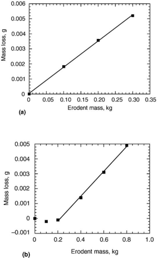
measurements of erosion rate. Figure 15(a)(a) shows data from a low carbon steel specimen eroded by three
100 g quantities of olivine sand in a gas-blast erosion test at 20 m/s and 30° impact angle. The plot is linear
(with a regression coefficient of 0.9997), leading to high confidence in the measured erosion value, and in this
case, a single test in which the specimen was exposed to 300 g of erodent would have yielded essentially the
same erosion rate.
Fig. 15(a)
Fig. 15(b)
Typical erosion data from tests in a gas-blast rig with 300–425 μm olivine sand particles. (a) Mild steel
specimen, 20 m/s, 30° impact angle. (b) Glass-bonded alumina ceramic specimen, 30 m/s, 90° impact
angle. Courtesy of D.N. Allsopp and I.M. Hutchings, University of Cambridge, UK

In some circumstances, as just noted, materials may exhibit an incubation period of lower mass loss, or even
mass gain, before steady state erosion occurs. Data showing this effect are illustrated in Fig. 15(b)(b) for a
sintered alumina ceramic sample eroded at 30 m/s and 90 ° impact angle. Linear behavior was exhibited only
after some 200 g of erodent had struck the specimen, but if a single measurement of mass loss had been made
after exposure to, for example, 400 or even 800 g of erodent, the resulting value of mean erosion rate would not
have accurately reflected the true steady state behavior of the sample. It is therefore essential that enough data
are gathered from the sample to enable its steady state erosion behavior to be accurately assessed. This may
involve preliminary testing to establish the exposure needed to achieve steady state conditions.
Although reproducibility within a single laboratory can be good, erosion test results obtained in different
laboratories often show greater variability (Ref 22). The most important source of this is in the method and
accuracy of measurement of particle velocity. Different methods of erosion testing may also introduce subtle,
but important, differences in the particle motion. For example, there is evidence (Ref 23) that particle rotation
plays an important role in explaining differences in erosion rate seen with gas-blast and rotating disk erosion
testers (Ref 13).
References cited in this section
13. A.J. Burnett, S.R. De Silva, and A.R. Reed, Comparisons between Sand Blast and Centripetal Effect
Accelerator Type Erosion Testers, Wear, Vol 186–187, 1995, p 168–178
22. A.W. Ruff, Analysis of Interlaboratory Test Results of Solid Particle Impingement Erosion, Wear, Vol
108, 1986, p 323–335
23. M.S.A. Bradley, University of Greenwich, UK, 1999, private communication
Solid Particle Erosive Wear Testing
Ian M. Hutchings, University of Cambridge (England)
Data Analysis and Interpretation
Most erosion tests are performed to determine the rate of material removal, and the primary measurement of
material loss is by weighing. Since the mass loss to be measured will usually be small, often less than 1 mg, it is
very important that the balance used to weigh the specimen has adequate sensitivity and long-term stability.
The latter point is important, since an erosion experiment may last for several hours or even days, and the
measurement involves determining small changes in the mass of a specimen that has a much larger mass itself.
The balance must be carefully zeroed before each weighing. Temperature control in the balance room may be
necessary, and a “control” specimen similar in mass to the erosion specimen but not exposed to erosion may be
useful to reduce random errors in weighing. A well-defined protocol must be adopted to clean the specimen (for
example, with a clean, dry blast of compressed air) before each weighing. With such precautions, and by using
a well-characterized erosion test operated under stable conditions, it is possible to achieve highly reproducible
measurements of erosion rate. Figure 15(a)(a) shows data from a low carbon steel specimen eroded by three
100 g quantities of olivine sand in a gas-blast erosion test at 20 m/s and 30° impact angle. The plot is linear
(with a regression coefficient of 0.9997), leading to high confidence in the measured erosion value, and in this
case, a single test in which the specimen was exposed to 300 g of erodent would have yielded essentially the
same erosion rate.
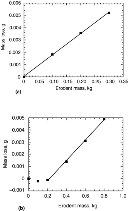
Fig. 15(a)
Fig. 15(b)
Typical erosion data from tests in a gas-blast rig with 300–425 μm olivine sand particles. (a) Mild steel
specimen, 20 m/s, 30° impact angle. (b) Glass-bonded alumina ceramic specimen, 30 m/s, 90° impact
angle. Courtesy of D.N. Allsopp and I.M. Hutchings, University of Cambridge, UK
In some circumstances, as just noted, materials may exhibit an incubation period of lower mass loss, or even
mass gain, before steady state erosion occurs. Data showing this effect are illustrated in Fig. 15(b)(b) for a
sintered alumina ceramic sample eroded at 30 m/s and 90 ° impact angle. Linear behavior was exhibited only
after some 200 g of erodent had struck the specimen, but if a single measurement of mass loss had been made
after exposure to, for example, 400 or even 800 g of erodent, the resulting value of mean erosion rate would not
have accurately reflected the true steady state behavior of the sample. It is therefore essential that enough data
are gathered from the sample to enable its steady state erosion behavior to be accurately assessed. This may
involve preliminary testing to establish the exposure needed to achieve steady state conditions.
Although reproducibility within a single laboratory can be good, erosion test results obtained in different
laboratories often show greater variability (Ref 22). The most important source of this is in the method and
accuracy of measurement of particle velocity. Different methods of erosion testing may also introduce subtle,
but important, differences in the particle motion. For example, there is evidence (Ref 23) that particle rotation
plays an important role in explaining differences in erosion rate seen with gas-blast and rotating disk erosion
testers (Ref 13).

References cited in this section
13. A.J. Burnett, S.R. De Silva, and A.R. Reed, Comparisons between Sand Blast and Centripetal Effect
Accelerator Type Erosion Testers, Wear, Vol 186–187, 1995, p 168–178
22. A.W. Ruff, Analysis of Interlaboratory Test Results of Solid Particle Impingement Erosion, Wear, Vol
108, 1986, p 323–335
23. M.S.A. Bradley, University of Greenwich, UK, 1999, private communication
Solid Particle Erosive Wear Testing
Ian M. Hutchings, University of Cambridge (England)
References
1. “Standard Terminology Relating to Wear and Erosion,” G 40, Annual Book of ASTM Standards, ASTM,
1998
2. I.M. Hutchings, Tribology: Friction and Wear of Engineering Materials, CRC Press, Inc., 1992, p 171–
197
3. Manual on Testing Sieving Methods, ASTM Manual 32, ASTM, 1998
4. “Test Sieving,” BS 1796-1, British Standards Institution, London (also ISO 2591-1)
5. P.H. Shipway and I.M. Hutchings, The Role of Particle Properties in the Erosion of Brittle Materials,
Wear, Vol 193, 1996, p 105–113
6. S. Bahadur and R. Badruddin, Erodent Particle Characterization and the Effect of Particle Size and
Shape on Erosion, Wear of Materials 1989, K.C. Ludema, Ed., ASME, 1989, p 143–153
7. “Standard Test Method for Conducting Erosion Tests by Solid Particle Impingement Using Gas Jets,” G
76, Annual Book of ASTM Standards, ASTM
8. G.L. Sheldon, J. Maji, and C.T. Crowe, Erosion of a Tube by Gas-Particle Flow, J. Eng. Mater.
Technol. (Trans. ASME), Vol 99, 1977, p 138–142
9. D.B. Marshall et al., Paticle Size Distribution Effects on the Solid Particle Erosion of Brittle Materials,
Wear, Vol 71, 1981, p 363–373
10. D.R. Andrews, S.M. Walley, and J.E. Field, Solid Particle Erosion Studies in the Cavendish Laboratory,
Paper 36, Proc. 6th Int. Conf. on Erosion by Liquid and Solid Impact, Cavendish Laboratory,
Cambridge, UK, 1983
11. P.H. Shipway and I.M. Hutchings, Influence of Nozzle Roughness on Conditions in a Gas-Blast Erosion
Rig, Wear, Vol 162–164, 1993, p 148–158
12. A.N.J. Stevenson and I.M. Hutchings, Scaling Laws for Particle Velocity in the Gas-Blast Erosion Test,
Wear, Vol 181–183, 1995, p 56–62

13. A.J. Burnett, S.R. De Silva, and A.R. Reed, Comparisons between Sand Blast and Centripetal Effect
Accelerator Type Erosion Testers, Wear, Vol 186–187, 1995, p 168–178
14. I.R. Kleis and K.K. Uuemyis, Mechanical Rigs for Studying Abrasive Erosion, Russ. Eng. J., Vol 51,
1971, p 13–15
15. S. Söderberg, S. Hogmark, U. Engman, and H. Swahn, Erosion Classification of Materials Using a
Centrifugal Erosion Tester, Tribol. Int., Dec 1981, p 333–343
16. W. Tabakoff, Experimental Study on the Effects of Specimen Sizes on Erosion, Wear, Vol 86, 1983, p
65–72
17. W. Tabakoff, M.F. Malak, and A. Hamed, AIAA J., Vol 25, 1987, p 721–726
18. J.E. Goodwin, W. Sage, and G.P. Tilly, Study of Erosion by Solid Particles, Proc. Inst. Mech. Eng., Vol
184, 1969, p 279–291
19. V. Ponnaganti, D.E. Stock, and G.L. Sheldon, Measurement of Particle Velocities in Erosion Processes,
Polyphase Flow and Transport Technology, R.A. Bajura, Ed., ASME, 1980, p 217–222
20. A.W. Ruff and L.K. Ives, Measurement of Solid Particle Velocity in Erosive Wear, Wear, Vol 35, 1975,
p 195–199
21. T.H. Kosel and K. Anand, An Optoelectronic Erodent Particle Velocimeter, Corrosion and Particle
Erosion at High Temperatures, V. Srinivasan and K. Vedula, Ed., The Minerals, Metals and Materials
Society, 1989, p 349–368
22. A.W. Ruff, Analysis of Interlaboratory Test Results of Solid Particle Impingement Erosion, Wear, Vol
108, 1986, p 323–335
23. M.S.A. Bradley, University of Greenwich, UK, 1999, private communication
Solid Particle Erosive Wear Testing
Ian M. Hutchings, University of Cambridge (England)
Selected References
• W.F. Adler, Ed., Erosion: Prevention and Useful Applications, ASTM Special Technical Publication
664, ASTM, 1977
• I. Finnie, Erosion of Surfaces by Solid Particles, Wear, Vol 3, 1960, p 87–103
• I.M. Hutchings, Tribology: Friction and Wear of Engineering Materials, CRC Press, Inc. and Edward
Arnold, London, 1992
• I.M. Hutchings and J.A. Little, Eds., Proc. 8th Int. Conf. on Erosion by Liquid and Solid Impact,
Cambridge, UK, published in Wear, Vol 186–187, 1995
• A.V. Levy, Solid Particle Erosion and Erosion-Corrosion of Materials, ASM International, 1995
• J.A. Little, Ed., Proc. Int. Conf. on Erosive and Abrasive Wear, Incorporating 9th Int. Conf. on Erosion
by Liquid and Solid Impact, Cambridge, UK, published in Wear, Vol 235, 1999
• C.M. Preece, Ed., Erosion, Treatise on Materials Science and Technology, Vol 16, Academic Press,
New York, 1979
