ASM Metals HandBook Vol. 8 - Mechanical Testing and Evaluation
Подождите немного. Документ загружается.


References cited in this section
10. J.H. Magee, Stainless Steels That Resist Wear and Galling, Stainl. Steel World, May 1997
11. J.H. Magee, Two Galling Resistant Stainless Steels Used for Bridge Hinge Pins, 14th Annual Bridge
Conference, June 1997 (Pittsburgh, PA), 1997, p 161–165
12. J.H. Magee, Wear of Stainless Steels, Friction, Lubrication, and Wear Technology, Vol 18, ASM
Handbook, P. Blau, Ed., ASM International, 1992, p 710–724
13. H.D. Merchant and K.J. Bhansali, “Metal Transfer and Galling in Metallic Systems,” Symposium
Proceeding, Oct 1986 (Orlando, FL), ASTM, 1987
Sliding Contact Damage Testing
Button-on-Block Galling Test
In the 1950s, a simple button-on-block test was developed to evaluate the galling resistance of material couples
(Ref 14). A specific version of this test is defined in ASTM G 98 (Ref 6, 15). This test is generally performed
on bare metals; however, nonmetallics, coatings, solid lubricants, and surface-modified alloys can be tested as
well.
The button-on-block test uses available laboratory equipment capable of maintaining a constant, compressive
load between two flat surfaces. Both a Brinell hardness tester and a tension-test machine have been used to
perform this test. Also, Falex Corporation, a designer and manufacturer of wear test equipment, has an
apparatus specifically designed for button-on-block testing.
For bare metal evaluations, both galling specimens (button and block) are ground with abrasive paper or
machine ground with an abrasive wheel. Both test surfaces should have a surface finish between 0.25 and 1.1
μm (10 and 45 μin.) for the arithmetic average surface roughness (R
a
). Specimen flatness should be maintained
at 0.33 mm/m (0.004 in./ft) to ensure 100% contact between the specimens during testing. The only critical
dimension for either specimen is the button diameter that constitutes the contact area. The standard diameter is
13 mm (0.5 in.); however, other button diameters can be used. If a different diameter is used, then it should be
reported since it can affect the test result. The block specimen must have sufficient area to accommodate at
least one test; however, most users have found that a block length between 75 and 150 mm (3 and 6 in.) is ideal
for this multiple sample test procedure. A reasonable block width is 19 mm (0. 5 in.), and a minimum width of
17 mm (0.625 in.) is necessary for testing a 13 mm (0.5 in.) button. Thickness is not critical.
Immediately prior to testing, both galling specimens are cleaned to remove machinery oils and metallic
particles. The following cleaning technique is suggested for metals in ASTM G 98. First, ultrasonically clean
the button and block in trichloroethane. Then, use a methanol rinse to remove any traces of trichloroethane
residue. Materials with open grains (powder metals or hardfaced alloys) must be dried to remove all traces of
the cleaning solvent that may be entrapped in the material. Note that because the use of trichloroethane is being
discouraged, any nonchlorinated, non-film-forming cleaning agent and solvent can be used as a substitute.
Once cleaned, the specimens are mounted in the loading device, and a light compressive load, for example, 110
N (25 lb), is applied to make sure the button is properly seated on the block. The button-on-block test setup is
shown in Fig. 7. A selected compressive load is then placed on the button specimen. This results in a specific
compressive stress for a 13 mm (0.5 in.) button sample. The selected load is dependent on educated judgment
of the galling resistance of the mated couples, that is, light loads for poor galling resistance and heavy loads for
excellent galling-resistant couples. Stress cannot exceed the compressive yield strength of the button material.
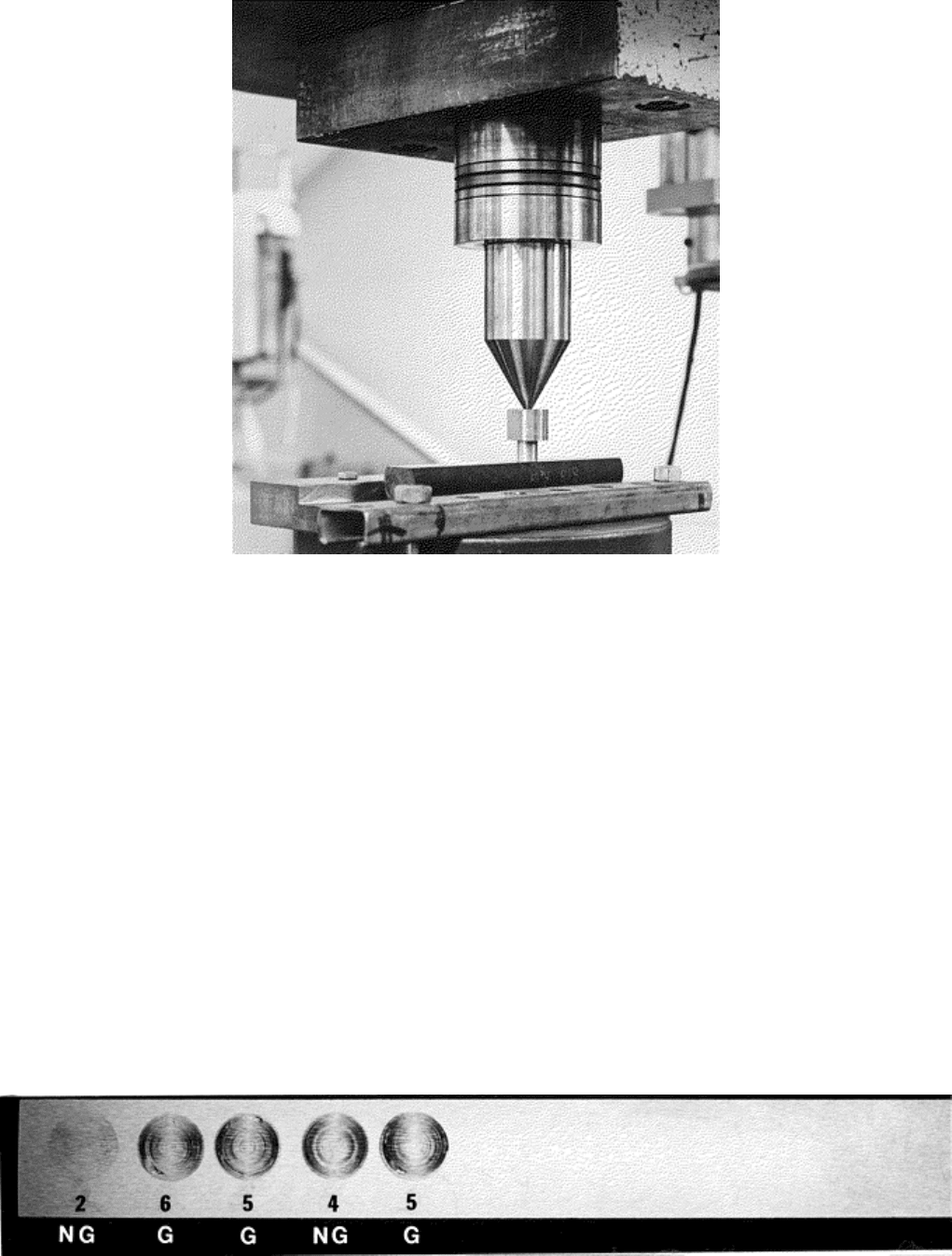
Fig. 7 Button-on-block galling test arrangement using a tension test machine. Source: Ref 16
Once loaded, the button is rotated slowly one revolution (360°) using either an open-end wrench, an adjustable
wrench, or some other special tool for rotating by hand. A mechanized system may also be used to rotate one
specimen relative to the other. The latter may allow torque measurement during testing. Actual sliding time
should be between 3 and 20 s. Rotation direction, clockwise or counterclockwise, is not specified in ASTM G
98; however, it should be noted. The compressive load is then removed, and the mated surfaces are visually
examined for galling. If specimens appear smooth and undamaged, to the unaided eye, the procedure is
repeated at a higher load with an untested button specimen at a new location on the block sample. A burnished
surface does not constitute a galled surface, nor does a scored surface. At least one of the contacting surfaces
must exhibit torn metal. Galling has a distinct, macroscopic appearance with protrusions of metal above the
original surface (Fig. 6).
If galling has occurred, testing is done at a lower load with a new button and block location to establish an
interval between the highest nongalled stress and galled stress. This interval is used to define the threshold
galling stress (TGS) and should be no greater than 34.5 MPa (5 ksi) for threshold stresses greater than 138 MPa
(20 ksi) and no greater than 21 MPa (3 ksi) for threshold stresses of 138 MPa (20 ksi) or less. If galling is
questionable or borderline, the test is repeated at a higher load to confirm the previous test result.
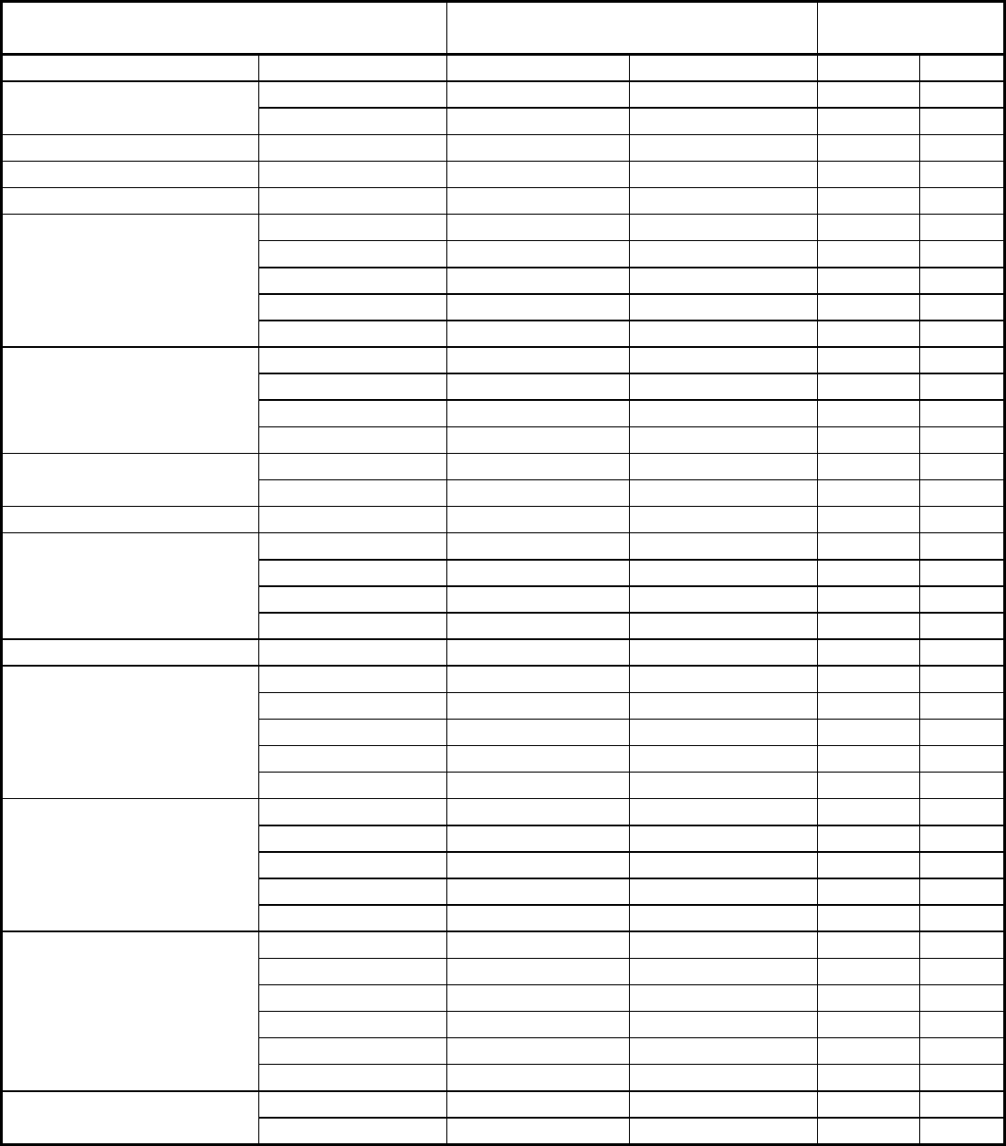
A typical series of galling tests is shown in Fig. 8. The reported TGS for the example is 34.5 MPa (4.5 ksi).
Since the galling stress is based on the button diameter contact, the button impression on the block should be
measured to determine if full contact occurred. At light loads, that may not be the case.
Fig. 8 Sequence of galling tests on block specimens. Source: Ref 17
Experience has shown that galling is most prevalent in sliding systems that are slow moving and operate
intermittently. The movement of threaded components or the opening and closing of valve components are
classic examples that this test method attempts to simulate. This test method has proved valuable in screening
materials for further prototypical testing that more closely simulates actual service conditions. The button and
block material do not have to be the same material and hardness. When dissimilar, the selection of the button
material should be the same as the sliding component being screened for the specific application.
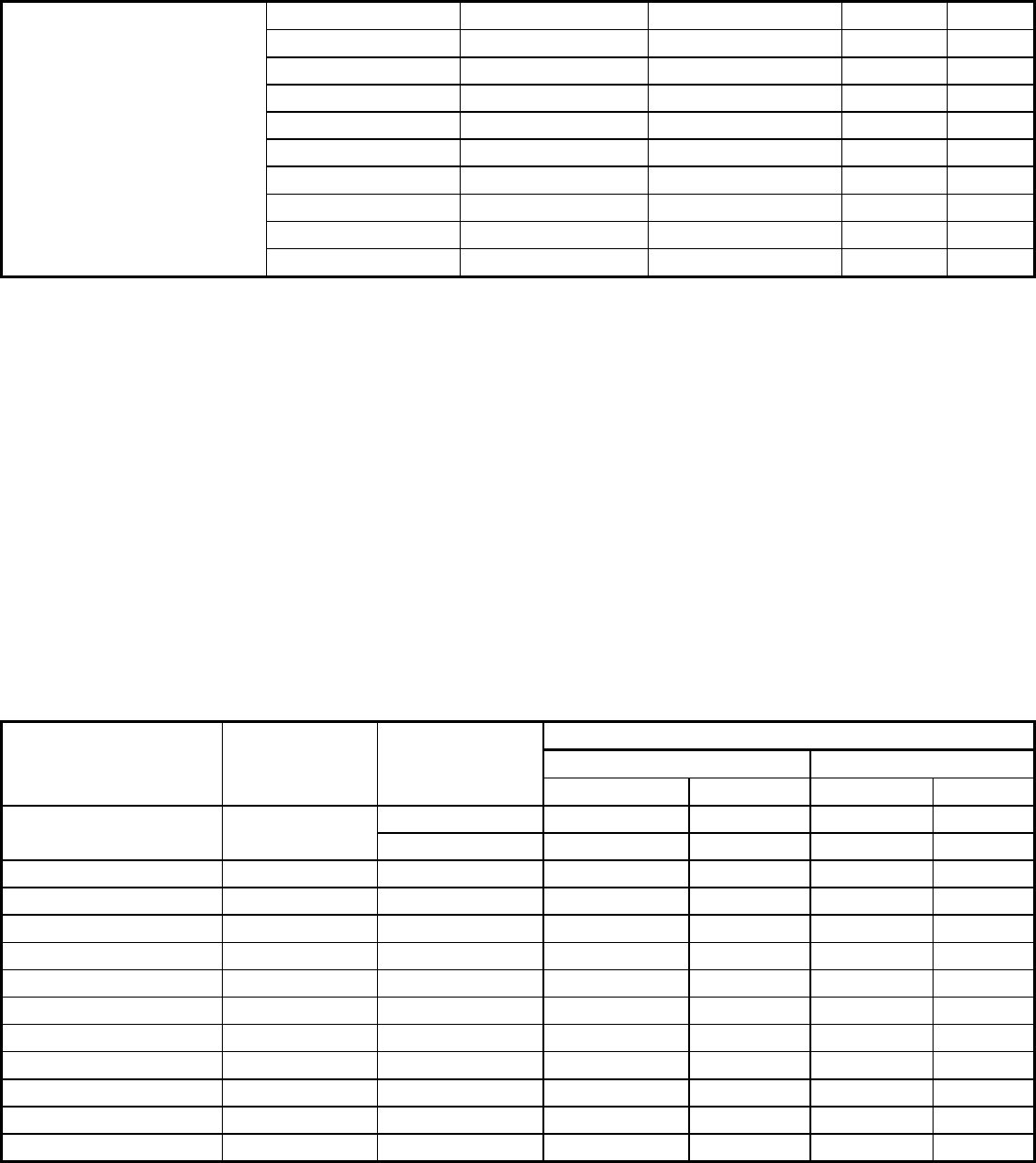
Table 2 lists threshold galling stress data for a variety of material couples using the button-on-block test.
Additional data can be found in Ref 12. This test is most popular for galling-prone materials, such as stainless
steels.
Table 2 Galling resistance of selected material couples (metal A vs. metal B)
Contact metal A Contact metal B
Threshold
galling stress
(a)
Alloy Hardness, HB Alloy Hardness, HB MPa
ksi
200 Silicon bronze 200 28
4
Silicon bronze
200 Type 304 140 304
44
A286 (S66286) 270 A286 270 21
3
AISI 4337 484 AISI 4337 415 14
2
AISI 1034 415 AISI 1034 415 14
2
141 Type 303 180 345+
50+
141 Type 201 202 345+
50+
141 Type 316 200 345+
50+
141 S17400 405 345+
50+
Waukesha 88
141 20Cr-80Ni 180 345+
50+
202 Type 201 202 104
15
202 Type 304 140 14
2
202 S17400 382 14
2
Type 201
202 Nitronic 32 231 248
36
169 Type 416 342 21
3
Type 301
169 Type 440C 560 21
3
Type 410 322 Type 420 472 21
3
342 Type 416 372 90
13
372 Type 410 322 28
4
342 Type 430 190 21
3
Type 416
342 20Cr-80Ni 180 48
7
Type 440C 560 Type 440C 604 76
11
311 Type 304 140 14
2
380 Nitronic 32 401 90
13
435 Type 304 140 14
2
400 S17700 400 21
3
S17400
435 S17700 435 14
2
235 S17400 380 76
11
401 Nitronic 32 401 235
34
235 Nitronic 32 401 235
34
235 Type 304 140 48
7
Nitronic 32 (S24100)
401 Type 304 140 90
13
205 AISI 1034 205 14
2
205 Nitronic 50 205 14
2
321 Nitronic 50 321 14
2
205 Nitronic 32 401 90
13
321 Nitronic 32 235 55
8
Nitronic 50 (S20910)
205 Type 304 140 28
4
205 Type 301 169 345+
50+
Nitronic 60 (S21800)
205 Type 420 472 345+
50+
213 S17400 313 345+
50+
205 S17400 332 345+
50+
205 Nitronic 50 205 345+
50+
205 S13800 297 345+
50+
205 S13800 437 345+
50+
205 AISI 4337 448 345+
50+
205 Stellite 6B 415 345+
50+
205 A286 270 338+
49+
205 20Cr-80Ni 180 248
36
205 Ti-6Al-4V 332 345+ 50+
(a) Values shown are unlubricated threshold galling stress for the button-on-block galling test. Values given as
50+ indicate the samples did not gall.
Source: Ref 14
Multiple-Rotation Button-on-Block Testing. A modification of the standard single-rotation test is a multiple-
rotation procedure. This change is designed to simulate the action of valve components. Also, repetitive sliding
across the same surface results in galling at lower stress values. Thus, alloys or coatings with good-to-excellent
galling resistance can be evaluated. This procedure is especially useful for screening materials for service
conditions known to be severe. One example of this multiple procedure is the triple-rotation test where the
button is turned counterclockwise (360°), clockwise (360°), and counterclockwise (360°). This modified
button-on-block test has been used to evaluate stainless steels with improved galling resistance and for testing
solid lubricants, such as molybdenum-disulfide. Table 3 compares various stainless steels using the single- and
triple-rotation tests. Most stainless alloys tested have significantly lower TGS values using the triple-rotation
tests. Those who use cobalt-base alloys, hardfaced materials, and metallic coatings, should consider a multiple-
rotation type of test procedure.
Table 3 Threshold galling stress results for selected self-mated stainless steels
Threshold galling stress
Single rotation
(a)
Triple rotation
Contact alloy UNS No. Hardness
MPa ksi MPa
ksi
95 HRB 104+ 15+ 104+
15+
Gall-Tough S20161
28 HRC 104+ 15+ 104+
15+
Nitronic 60 S21800 92 HRB 104+ 15+ 48
7
Nitronic 50 S24100 23 HRC 97 14 14
2
18-18 Plus S28200 96 HRB 166 24 7
1
Type 303 S30300 85 HRB 138 20 <7
<1
Type 304 S30400 86 HRB 55 8 <7
<1
Type 420 S42000 49 HRC 55 8 14
2
Trimrita S42010 50 HRC 104+ 15+ 21
3
Type 430 S43000 98 HRB 10 1.5 <7
<1
Custom 630 S44004 55 HRC 124 18 14
2
Custom 455 S45500 48 HRC 97 13 <7
<1
A 286 S66286 30 HRC 14 2 <7 <1
(a) Button-on-block test, unlubricated ground finish. +, did not gall. <, galled at this stress.
(b) ASTM G 98.
Source: Ref 12
References cited in this section
6. Friction and Wear Testing: Source Book of Selected References from ASTM Standards and ASM
Handbooks, ASM International, 1997

12. J.H. Magee, Wear of Stainless Steels, Friction, Lubrication, and Wear Technology, Vol 18, ASM
Handbook, P. Blau, Ed., ASM International, 1992, p 710–724
14. Committee of Stainless Steel Producers, “Review of the Wear and Galling Characteristics of Stainless
Steels,” American Iron and Steel Institute, April 1978, p 8
15. “Standard Test Method for Galling Resistance of Materials,” ASTM G 98, Annual Book of ASTM
Standards
16. J.H. Magee, Austenitic Stainless Steels with Improved Galling Resistance, High Manganese Austenitic
Stainless Steels, ASM International, 1987, p 62
17. J.H. Magee, “Development of Stainless Steel Galling Test,” Carpenter Technology Corporation, 1987
Sliding Contact Damage Testing
Profilometry Evaluation of Galling Damage
Instead of a visual determination to assess galling damage, surface profilometry has been used. Several test
procedures can be found in the literature (Ref 18, 19, 20). One example is a galling procedure that involves the
twisting of a cylindrical 16 mm ( in.) diameter pin against a block. Tests are performed at three selected loads.
Cylindrical pins are slowly tested back and forth 10 times, through an arc of 120° at each load, using a new pin
and block location per load. Scar profiles are measured using a profilometer. The difference in peak-to-valley
amplitudes between the final roughness and the initial roughness (measured in microns) is plotted versus load.
Resistance to galling is quantified by the degree of damage (measured in microns) as shown in Fig. 9. This 10-
turn test is designed to evaluate excellent galling-resistant materials such as Stellite alloy No. 6, against other
materials. Damage measured by this test typically does not reach the level of surface damage observed in the
button-on-block test, that is, macroscopic protrusions of metal above the surface. Note that when stainless
steels, such as type 304, 316, and 410, are evaluated self-mated using this procedure, severe damage occurs at
relatively low loads with only one or two twists possible before total seizure.
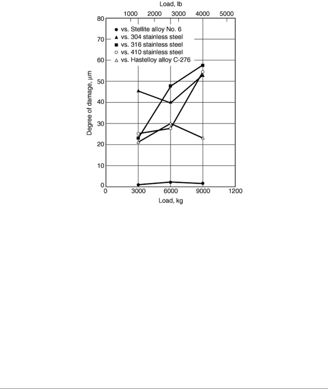
Fig. 9 Resistance to galling of Stellite alloy No. 6 (surface ground counterface) versus selected materials.
Source: Ref 20
References cited in this section
18. P. Crook, The Development of a Series of Wear Resistant Materials Akin to Those of the Cobalt-
Chromium Alloys, Wear of Materials Conf. (1981), S.K. Rhee, A.W. Ruff, and K. Ludema, Ed.,
American Society of Mechanical Engineers, 1981, p 202–209
19. W. Schumacher, The Galling Resistance of Silver, Tin and Chrome Plated Stainless Steels, Wear of
Materials Conf. 1981, S.K. Rhee, A.W. Ruff, and K. Ludema, Ed., American Society of Mechanical
Engineers, 1981, p 186–196
20. R.W. Kirchner, P. Crook, and A. Asphahani, “Wear/Corrosion-Resistant High Performance Alloys for
the Food Industries,” Paper 102, presented at Corrosion 1984, April 1984 (New Orleans), National
Association of Corrosion Engineers, 1984
Sliding Contact Damage Testing
Pin-on-Flat Galling Test
A second example of a procedure that uses surface profilometry to measure galling damage is the pin-on-flat
test (Ref 21). In this test, a spherically tipped pin slides in a straight line against a flat surface (Fig. 10). Unlike
the procedures previously discussed, there is no twisting action, nor is the button surface flat. A single pass with
a distance of 40 mm (1.5 in.) is employed at a speed of 2 mm/s (0.8 in./s) and a load of 130 N (30 lb). Surface
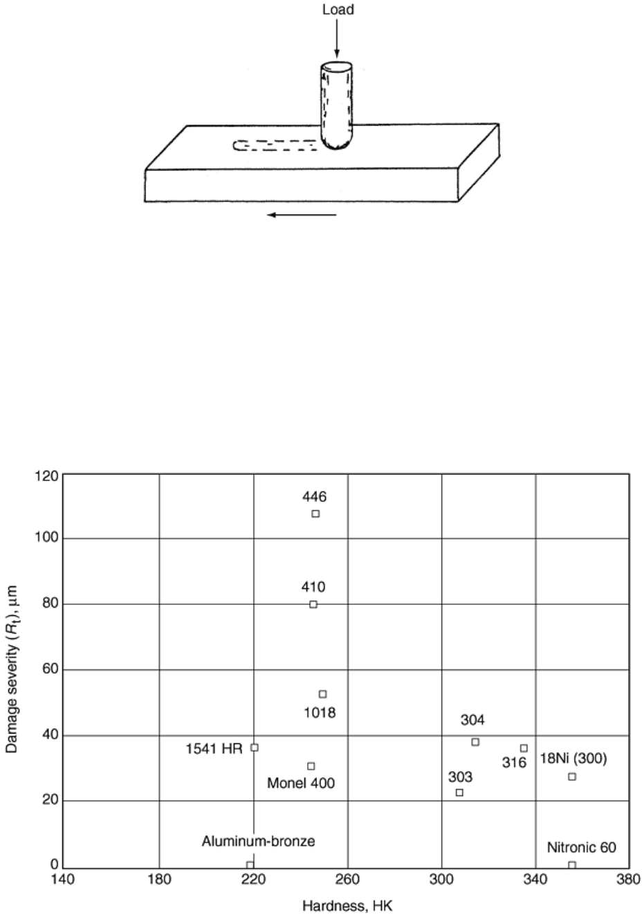
finish of the specimens is produced by a 6 μm polish, and the pin diameter is 13 mm (0.5 in.). A pin tip radius
of 25 mm (1 in.) is used. As with all galling evaluations discussed, specimens are thoroughly cleaned in an
ultrasonic bath and then alcohol rinsed prior to testing.
Fig. 10 Pin-on-flat galling test configuration. Source: Ref 21
The topography of the damage is measured on the flat specimen by means of a stylus profilometer. A series of
parallel traces at a spacing of approximately 0.3 mm (0.012 in.) is taken over the entire length of the track. The
tracing direction is perpendicular to the sliding direction. Profile data are acquired in digital form, yielding a
matrix of values that specify the elevation of points on the surface. A significant parameter, R
t
, determined by
these profilometry measurements, is the average maximum peak-to-valley distances (microns) for traces taken
across the surface damage area. This parameter reflects the importance of the large protrusions and deep gouges
that are characteristic of galling. Galling tendency of material is a function of the R
t
value. Figure 11 plots
damage severity (R
t
) versus Knoop hardness for a wide variety of materials. The results show there is no overall
correlation of damage severity with hardness. Aluminum-bronze, a known galling-resistant material, had no
surface damage, while galling-prone alloys (such as type 410 stainless steel) had significant damage.
Fig. 11 Damage severity (R
t
) as measured by profilometry plotted against hardness for several
commercial alloys. Source: Ref 21

Reference cited in this section
21. L.K. Ives, M.B. Peterson, and E.P. Whitenton, “Galling: Mechanism and Measurement,” National
Bureau of Standards Report, 1987, p 33–40
Sliding Contact Damage Testing
Threaded Connection Galling Tests
The galling tests described previously have been designed to rank material couples as a screening evaluation for
prototype testing. Prototype tests tend to be more expensive and are designed for a specific application. Several
threaded connections tests exemplify prototype testing (Ref 22, 23, 24). They are designed to determine if
galling or seizure is a problem when inserting and removing threaded connections.
The first example involves evaluating a bolted joint design consisting of a socket head captive screw, a stainless
flat washer, a helical lock washer, a stainless steel threaded insert, and a 19 mm (¾ in.) thick drawer manifold
to be bolted to the casting of a computer cabinet. In this test, each screw was inserted manually to minimize the
chance of cross-threading, then torqued to a specified level, loosened, and removed completely. This sequence
was repeated until galling or severe thread damage occurred. Variables evaluated were screw and insert
material, molybdenum-disulfide lubricant, cadmium or nickel-plated screws, and thread type. The life-cycle
design requirement was 900 cycles. Results of two of these tests can be found in Table 4.
Table 4 Sample results of two threaded connection galling tests
Test
Screw
material
Insert
material
Number
of cycles
to
galling
of
threads
1
17-4 PH stainless steel, ⅜–24 in., UNF-3A, 41
HRC, nonlubricated
Type 303 stainless steel hole, ⅜–24
in., UNF-3B, 89 HRB
225
2
17-4 PH stainless steel, H1050, ⅜–24 in., UNF-
3A, 31 HRC, nonlubricated
Nitronic 60 hole, ⅜–24 in., UNF-
3B, 96 HRB
1000
Source: Ref 22
Other examples of prototype tests involve threaded tubular products for deep and gas wells. These connections
are prone to galling due to the high torque applied in the makeup operation, that is, near the yield strength of
some alloys. Prototype tests were developed to evaluate this condition especially to determine the effectiveness
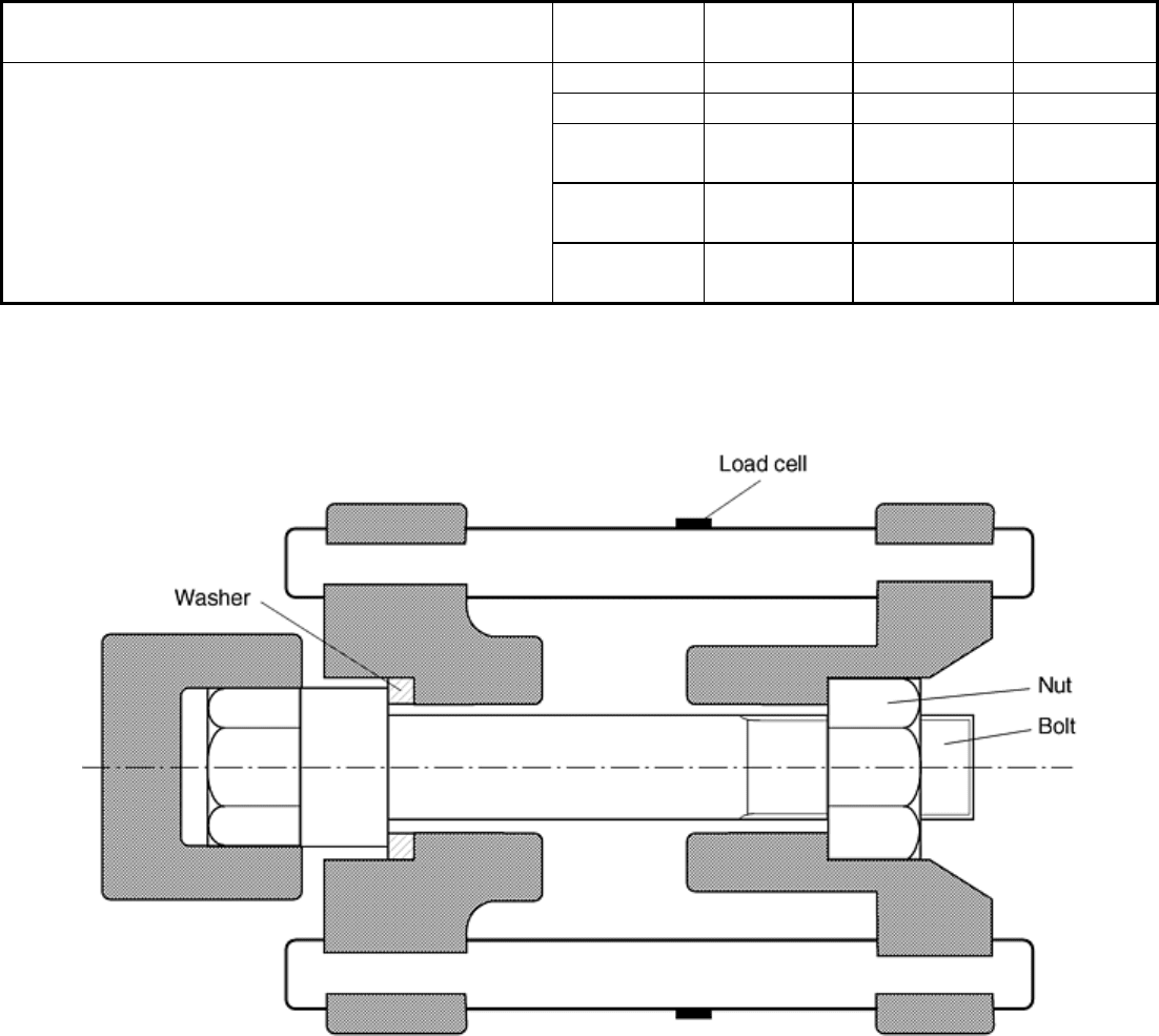
of lubricants or surface treatments. A bolt-nut test apparatus was designed to closely simulate a threaded tubular
makeup (Fig. 12) (Ref 23). Lubricants were applied to bolts and nuts according to manufacturer directions, and
the makeup torque was applied. The calculated surface stress on the threaded parts and bolt-to-washer mating
parts corresponded to metal-to-metal seal parts in actual threads. The makeup speed was slow: 3 rpm. Torque
and clamping force were measured. After each makeup and break operation, the threaded parts and bolt-to-
washer mating parts were inspected for galling. The lubricant performance was evaluated principally by noting
the number of makeup and break cycles until galling was first observed. Also, the variation of torque
coefficient was monitored during the test. Typical results are shown in Table 5. Longer test times of 30 days in
the fastened state prior to breakout have been evaluated by this method as have higher-temperature test
conditions to simulate deep-well service.
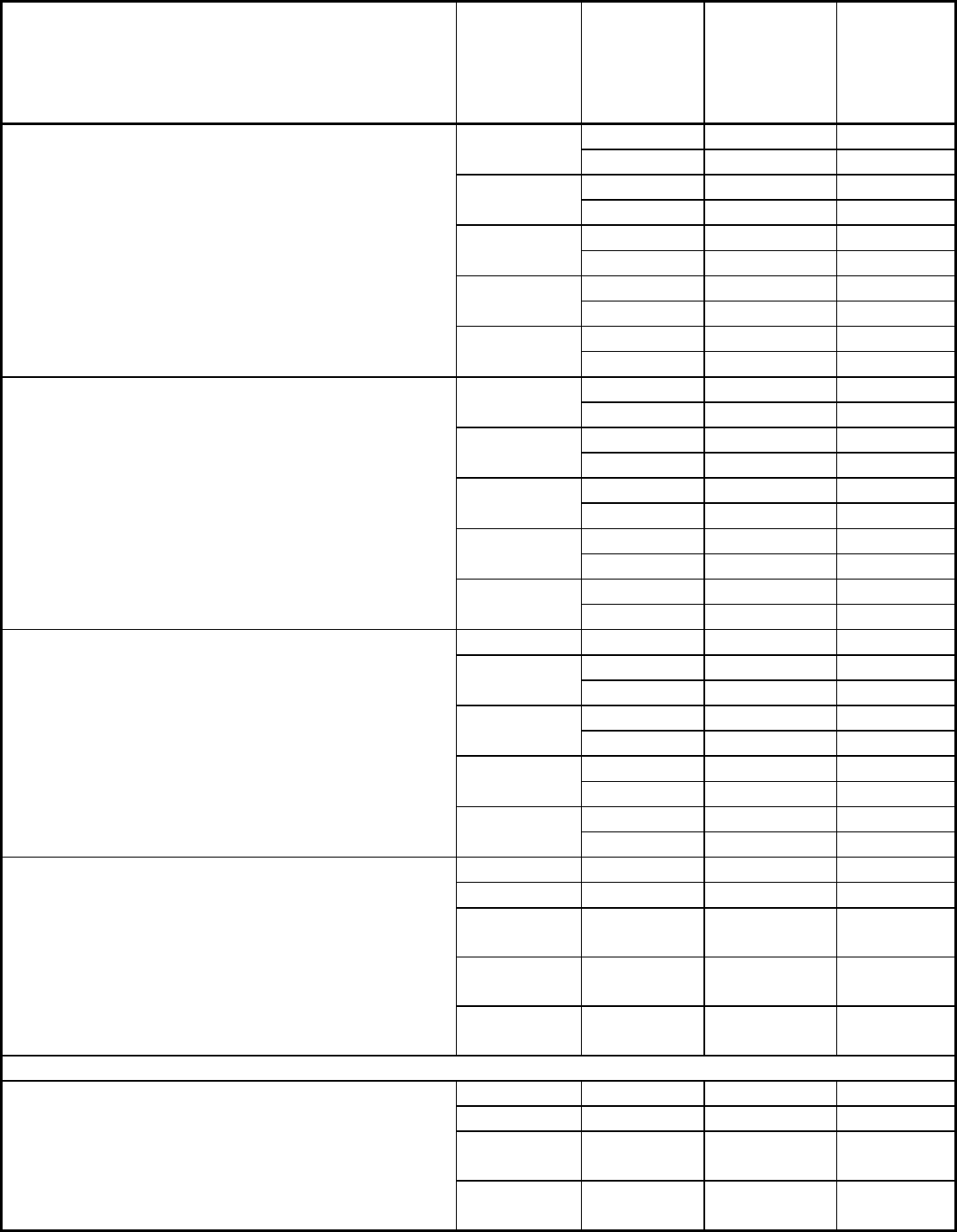
Table 5 Bolt-nut test results on the lubrication performance of various lubricants under different test
condition
Lubricant Test and
condition
Makeup
and break
cycles until
galling
observed
Torque
coefficient
(a)
at
first
makeup
Variation
of
torque
coefficient,
%
20 73 × 10
-3
+7, -6
None
(b)
102
-16
(b)
121
+9
API grease
(b)
124
+11
9 139
+3, -2
API grease
+ sand
(b)
125
+18
24 146
-14
API grease
+ water
(b)
125
+5, -6
22 149
+7, -7
MoS
2
-Sb
2
O
3
-epoxyester film
API grease
+ brine
(b)
127
+9, -13
9 189
+21
None
8 314
-14
6 165
-16
API grease
(b)
164
-22
14 202
-31
API grease
+ sand
7.5 175
-14
22 146
-23
API grease
+ water
19 167
-30
18 159
-16
Commercial organic resin bonded lubricant
containing MoS
2
(MIL-L-23398, 46147, 8937B)
API grease
+ brine
10 159
-21
None 8 161
+9
9 153
-7
API grease
15 152
-11
11 160
-10
API grease
+ sand
7.5 154
-3
8 124
+10
API grease
+ water
7 145
-9
8 158
-15
Commercial paste containing polyalkyleneglycol,
lithium soap and MoS
2
API grease
+ brine
7.5 140
+11, -1
None 1 310 × 10
-3
…
API grease
(b)
171
+1, -14
API grease
+ sand
10 191
-17
API grease
+ water
23 157
+10
Electroplated copper film
(c)
API grease
+ brine
(b)
158
-17
Heat treated films
None
(b)
82
-16
API grease
(b)
147
+21, -3
API grease
+ sand
(b)
135
+10
MoS
2
-Sb
2
O
3
-epoxyester film, heat treated at 250 °C
(480 °F) × 30 min in air
API grease
+ water
(b)
136
+13
API grease
+ brine
(b)
140
+7, -3
None 22 57
+2, -11
API grease
(b)
125
+5, -12
API grease
+ sand
20 127
+32
API grease
+ water
(b)
124
+29
Commercial organic resin-bonded lubricant
containing MoS
2
(MIL-L-23398, 46147, 8937B),
heat treated at 250 °C (480 °F) × 30 min in air
API grease
+ brine
(b)
120 +26
(a) Torque coefficient (C) relates torque (T) to bolt tension (F) and bolt diameter (D) as follows: T = CDF.
(b) No galling after 25 makeup and break cycles.
(c) Copper striking followed by electroplating in CuSO
4
bath (15 μm, or 40 μin. thick). API, American
Petroleum Institute.
Source: Ref 23
Fig. 12 Bolt-nut galling test apparatus. Source: Ref 23
Another oil-country threaded tubular test involves thick-walled, high-alloy products such as nonmagnetic drill
collars. These 9 m (30 ft) long collars are prone to galling when their threaded box and pin connections are
released after being joined with high makeup torques. These connections require an antigalling lubricant or
surface treatment, such as ion implantation (Ref 25). To evaluate their effectiveness, make/break galling tests
are performed. Full-size connections are machined with threads and lubricant/surface treatments are applied. A
large torque machine then “makes” the connection at a specified torque, appropriate for the threaded tubular
size, then breaks the connection. The breakout torque is recorded. This procedure is repeated several times
(typically 5 to 10 times). Alignment of the box/pin connection is important to prevent galling. After testing, the
threads and seal surfaces of the box and pin tubulars are examined for galling. Test results simply report
whether or not galling occurred.
References cited in this section
22. D.D. Vo and C.E. Wissing, Jr., Failures of Bolted Connections Due to Wear and Galling in Bolt
Threads, Proc. Use of New Technology to Improve Mechanical Readiness, Reliability and
Maintainability, Cambridge, 1985
