ASM Metals HandBook Vol. 8 - Mechanical Testing and Evaluation
Подождите немного. Документ загружается.

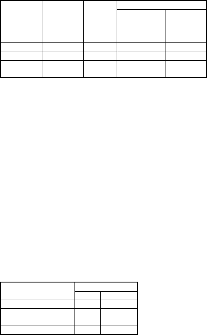
Brinell hardness number, HB
Scleroscope
hardness
Rockwell C
hardness
number,
HRC
Vickers
hardness
number,
HV
10 mm
standard ball,
3000 kgf
load
10 mm
carbide ball,
3000 kgf
load
36.3 23 254 243
243
35.5 22 248 237
237
34.8 21 243 231
231
34.2 20 238 226 226
Note: These Scleroscope hardness conversions are based on Vickers/Scleroscope hardness relationships
developed from Vickers hardness data provided by the National Bureau of Standards for 13 steel reference
blocks. Scleroscope hardness values obtained on these blocks by the Shore Instrument and Mfg. Co. Inc., the
Roll Manufacturers Institute, and members of this institute, and also on hardness conversions previously
published by the American Society for Metals and the Roll Manufacturers Institute.
Source: Ref 1
Both models of Scleroscopes can be mounted on various types of bases, although the model C Scleroscope is
commonly used unmounted when testing large workpieces with a minimum weight of 2.3 kg (5 lb). Due to its
critical vertical alignment, the model D Scleroscope should not be used unmounted, as erroneous readings may
result.
Workpiece Surface Finish. In Scleroscope-hardness testing, certain workpiece surface finish requirements must
be met in order to obtain accurate, consistent readings. An excessively coarse surface finish will yield erratic
readings; when necessary, the surface of the workpiece should be filed, machined, ground, or polished.
Care should be taken to avoid overheating or excessively cold working the surface. The surface finish required
to obtain reproducible results varies with the hardness of the workpiece. In proceeding from soft metals to
hardened steel, the required surface finish ranges from a minimum finish, as produced by a No. 2 file, to a
finely ground or polished finish.
Limitations on Workpiece and Case Thickness. Case-hardened steel with cases as thin as 0.25 mm (0.010 in.)
can be accurately hardness tested provided the core hardness is no less than 30 Scleroscope. Softer cores require
a minimum case thickness of 0.38 mm (0.015 in.) for accurate results.
Thin strip or sheet may be tested, with some limitations, but only when the Scleroscope hardness tester is
mounted in a clamping stand. Ideally, the sheet should be flat and without undulation. If the sheet material is
bowed, the concave side should be placed upwards to preclude any possibility of erroneous readings due to
spring effect. The minimum thicknesses of sheet in various categories that may be hardness tested with a
Scleroscope are as follows:
Minimum thickness
Metal
mm
in.
Hardened steel 0.13
(0.005)
Cold-finished steel strip
0.25
(0.010)
Annealed brass strip 0.38
(0.015)
Half-hard brass strip 0.25 (0.010)
Test Procedure. To perform a hardness test with either the model C or the model D Scleroscope, the tester
should be held or set in a vertical position, with the bottom of the barrel in firm contact with the workpiece. The
hammer is elevated and then allowed to fall and strike the surface of the workpiece. The height of rebound is
then measured, which indicates the hardness.
When using the model C Scleroscope, the hammer is elevated by squeezing a pneumatic bulb. The hammer is
released by again squeezing the bulb. When using the model D Scleroscope, the hammer is elevated by turning
a knurled control knob clockwise until a definite stop is reached. The hammer strikes the workpiece when the
control knob is released, and the reading is recorded on a dial. Hard steel tests about 100, medium-hard about
50, and soft metals 10 to 15.
Vertical Alignment. To minimize error, the hardness tester must be set or held in a vertical position, using the
plumb rod or level on the machine to determine vertical alignment. The most accurate readings are obtained
with the Scleroscope hardness tester mounted in a C-frame base that rests on three points, two of which are
adjustable to facilitate leveling of the anvil and to ensure vertical alignment of the barrel. When using a
mounted tester, the opposite sides of the workpiece must be parallel to each other. Vibration impedes the free
fall of the hammer, thereby producing low readings, and must be avoided.
Spacing of Indentations. Indentations should be singly spaced at least 0.50 mm (0.020 in.) apart. Flat
workpieces with parallel surfaces may be hardness tested within 6 mm (0.25 in.) of the edge when properly
clamped.
Taking the Readings. Experience is necessary to interpret readings accurately on a model C Scleroscope
hardness tester. Thin materials, or those weighing less than 2.3 kg (5 lb), must be securely clamped to absorb
the inertia of the hammer. The sound of the impact is an indication of the effectiveness of the clamping; a dull
thud indicates that the workpiece has been clamped solidly, whereas a hollow ringing sound indicates that the
workpiece is not tightly clamped or is warped and not properly supported. Five hardness determinations should
be made, and their average taken as representative of the hardness of a particular workpiece.
Calibration. Scleroscope hardness testers are supplied with reference bars (or test blocks) of known hardness.
The reference bars can be used correctly only with the Scleroscope mounted in a clamping stand, because they
do not have sufficient mass to produce a full rebound of the hammer unless firmly clamped. If actual
Scleroscope readings do not correspond to the values of the reference bars, the instrument should be returned to
the manufacturer for service.
Advantages. The Scleroscope hardness test has several advantages. Tests can be made very rapidly; over 1000
tests per hour are possible. Operation is simple and does not require highly skilled technicians.
The model C Scleroscope is portable and can be used unmounted for testing workpieces of unlimited size (rolls
and large dies). The Scleroscope hardness test is considered a nonmarring test; no obvious crater is left and only
in the most unusual instances would the tiny hammer mark be objectionable on a finished workpiece.
Additionally, a single scale covers the entire hardness range from the softest to the hardest metals.
Limitations of the Scleroscope hardness test include the necessity of keeping the test instrument in a vertical
position so that the hammer can fall freely. Scleroscope hardness tests are more sensitive to variations in
surface conditions than other hardness tests are. Because readings taken with the model C Scleroscope are
indicated by the maximum rebound of the hammer on the first bounce, even the most experienced operators
may disagree by one or two points. Also, the mass or configuration of the part can affect the accuracy of
readings.
Leeb Scale (Equotip) Hardness Testing
Leeb testers (Fig. 3) are portable hardness testers that operate on a dynamic rebound principal similar to the
Scleroscope. An impact device is propelled into the sample using a spring for the initial energy. The impact
device travels a short distance until it contacts the sample. A small indent is formed, and the impact device
rebounds away from the test surface according to the hardness and elasticity of the material. An electronic
induction coil measures the velocity of the impact device before and after it contacts the sample. The Leeb
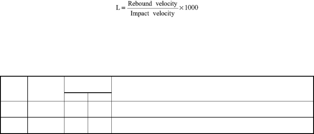
hardness number is defined as the following:
The Leeb hardness number is followed by “HL,” with one or more suffix characters representing the impact
device (Table 2). Leeb hardness is also known as Equotip hardness (for example, in ASTM A 956 “Standard
Test Method for Equotip Hardness Testing of Steel Products”). (Equotip is the trademark of PROCEQ SA,
Zurich, Switzerland.)
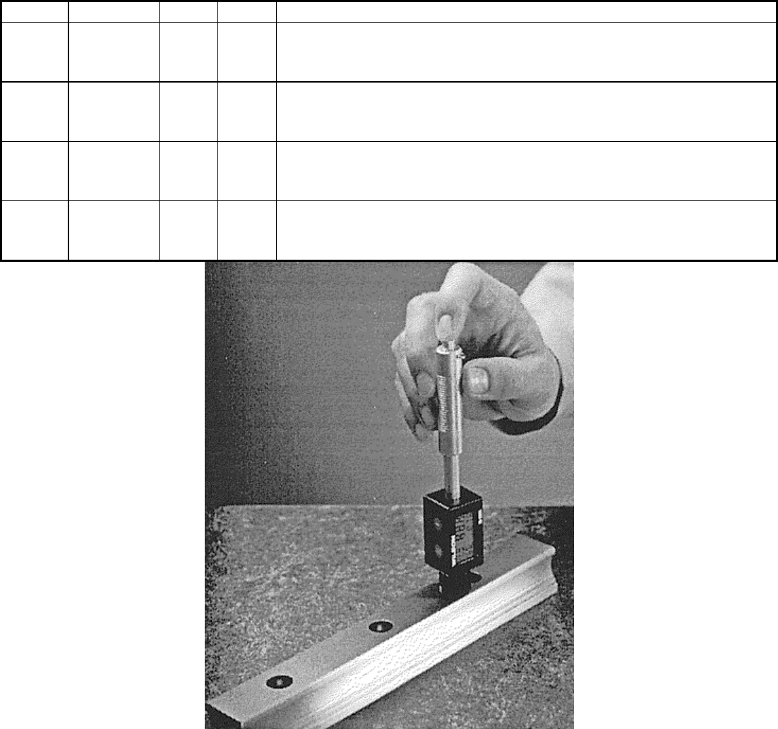
Table 2 Application guidelines for Leeb hardness testers
Minimum
sample size
Impact
device
Maximum
hardness,
HRC
kg lb
Description and use guidelines
D 68 5 11
The basic impact device used for most testing of forged and cast
steels, aluminum alloys, copper alloys, and cast irons
DC 68 5 11
A special impact device designed to make hardness measurements
in very confined spaces such as bores. Material applications are the
same as those for the D device.
D + 15 68 5 11
A special impact device, very slim with the measuring coil set back
for access to small holes and grooves. Material applications are the
same as those for the D device.
G 60 15 33
A special impact device, larger in size and impact energy than the
other devices, for use on large, heavy test pieces. For testing of steel
forgings, cast iron, and cast steel
C 68 1.5 3.3
A special impact device with low impact energy that can be used
for testing of surface-hardened components, coatings, and thin-
walled components of steel
E 70 5 11 A special impact device, with a synthetic diamond test tip that can
be used for testing of steel forgings or castings with extremely high
hardness
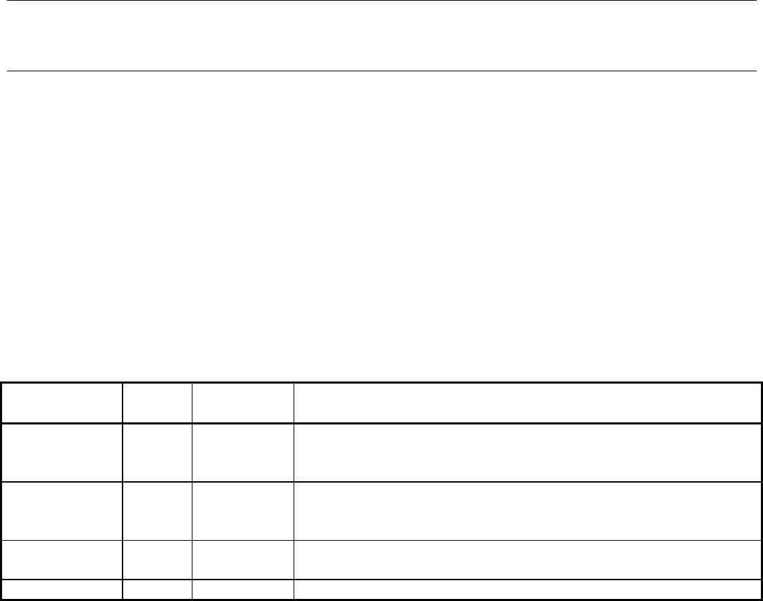
Fig. 3 Handheld Leeb hardness tester
Testers. By definition, all Leeb testers are electronic; therefore, they display the hardness result digitally. There
are several different types available to test a variety of different size and shape samples (Table 2). The D model
is the most common and suits a wide variety of materials. All models use either a tungsten carbide ball or
diamond as the indenter part of the impact device. Since the Leeb hardness value is not recognized universally,
most of the testers provide a built-in conversion to the other more common hardness scales (Rockwell, Brinell,
Vickers, and Scleroscope). The problem with these conversions is that they are very material dependent, usually
a function of the elastic modulus of the material. Therefore, most units include separate conversion data for
several different classes of materials. Steels, cast iron, aluminum, and brass are some of the materials normally
included internal to the tester.
Operation of the Tester. The Leeb testers are very simple to use. First, it is necessary to compress the impact
device against the spring and lock it in place. Then the unit is positioned carefully over the test point, making
sure that it is perpendicular to the surface. The release button is then pressed, allowing the impact device to be
propelled into the sample. As soon as the impact is felt, the result is indicated on the digital display.
Applications. Table 2 shows the normal applications for the various types. Since the test uses a rebound
principle, the mass of the sample is critical to the test result. Table 2 shows the desired minimum mass of the
sample for the different types. Smaller masses can be tested by carefully coupling the sample to a larger mass.
The Leeb testers also normally have the ability to test at various angles. Correction factors are frequently built
into the tester or provided as a table. The table provides a value to be subtracted from the result to account for
the effect of gravity on the velocity of the impact device when testing in any position other than vertical.
Like all hardness tests, the surface finish of the test point is important to the accuracy of the results. Rougher
surfaces will normally give softer results. Concave or convex surfaces can be tested with a Leeb tester if the
radius of curvature is greater than 30 mm (1.18 in.) for all units except the G type, which requires a radius of 50
mm (2 in.). Most testers can be purchased with a variety of adapters to facilitate the testing of various round and
odd surfaces.
Calibration. The only method to verify the calibration of Leeb testers is by using standardized test blocks. The
procedure is to make ten readings on the test surface of the blocks and average the readings. If the average is
within 13 numbers of the calibration certificate, the unit is considered calibrated. A limited number of hardness
ranges are available from the manufacturers.
Reference cited in this section
1. “Standard Hardness Conversion Tables for Metals,” E 140, Annual Book of ASTM Standards, ASTM,
1997
Miscellaneous Hardness Tests
Edward L. Tobolski, Wilson Instrument Division, Instron Corporation
Durometer Hardness Testing
The durometer is a hand-sized instrument that measures the indentation hardness of rubber and plastic products.
It is manually applied to the test specimen, and the reading is observed on a dial or digital indicator. Laboratory
accuracy can also be obtained by mounting the durometer on one of several types of operating stands.
Durometer hardness is the resistance of the material being tested to the penetration of the indenter as the result
of a variable force applied to the indenter by a spring. An infinitely hard material would yield a durometer
hardness of 100, because there would be zero penetration.
Durometer selection depends on the material being tested. Several types of durometers are available, as shown
in Table 3. All of these conform to ASTM D 2240, “Standard Test Method for Rubber Property—Durometer
Hardness.”
Table 3 Specifications of durometers
Durometer
type
Main
spring
Indenter
Applications
A (conforms to
ASTM D 2240)
822 g Frustum
cone
Soft vulcanized rubber and all elastomeric materials, natural
rubber, GR-S, GR-I, neoprene, nitrile rubbers, Thiokol, flexible
polyester cast resins, polyacrylic esters, wax, felt, leather, etc.
B 822 g Sharp 30°
included
angle
Moderately hard rubber such as typewriter rollers, platens, etc.
C 4.54 kg
(10 lb)
Frustum
cone
Medium-hard rubber and plastics
D (conforms to 4.54 kg Sharp 30°
Hard rubber and the harder grades of plastics such as rigid
ASTM D 2240)
(10 lb) included
angle
thermoplastic sheet, Plexiglas (AtoHaas Americas, Inc.,
Philadelphia, PA), polystyrene, vinyl sheet, cellulose acetate and
thermosetting laminates such as formica (Formica Corp.,
Cincinnati, OH), paper-filled calendar rolls, calendar bowls,
etc.
D0 4.54 kg
(10 lb)
2.38 mm (
in.) sphere
Very dense textile windings, slasher beams, etc.
0 822 g
2.38 mm (
in.) sphere
Soft printer rollers, Artgum, medium-density textile windings
of rayon, orlon, nylon, etc.
00 113 g
(4 oz)
2.38 mm (
in.) sphere
Sponge rubber and plastics, low-density textile windings; not
for use on foamed latex
000 (available
with round dial
only)
113 g
(4 oz)
12.7 mm
(½in.) diam
spherical
Ultrasoft sponge rubber and plastic
T 822 g 2.38 mm
( in.)
sphere
Medium-density textile windings on spools and bobbins with a
maximum diameter of 100 mm (4 in.); types T and T-2 have a
concave bottom plate to facilitate centering on cylindrical
specimens
With the exceptions of types 00 and M, all durometer types are variations of the ASTM types A and D
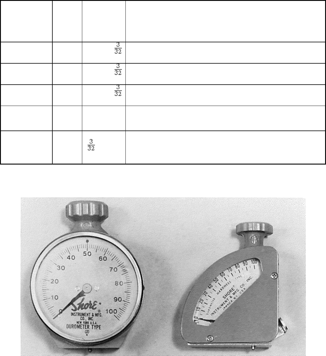
specifications by changing the indenters and/or load springs. Durometers are available with either a round or
quadrant style face (Fig. 4) or with a digital display (Fig. 5). The M style is not available in the quadrant design.
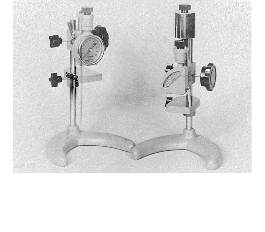
Pencil-style durometers are also available, but only in the A scale (Fig. 6).
Fig. 4 Round- and quadrant-style durometer hardness testers
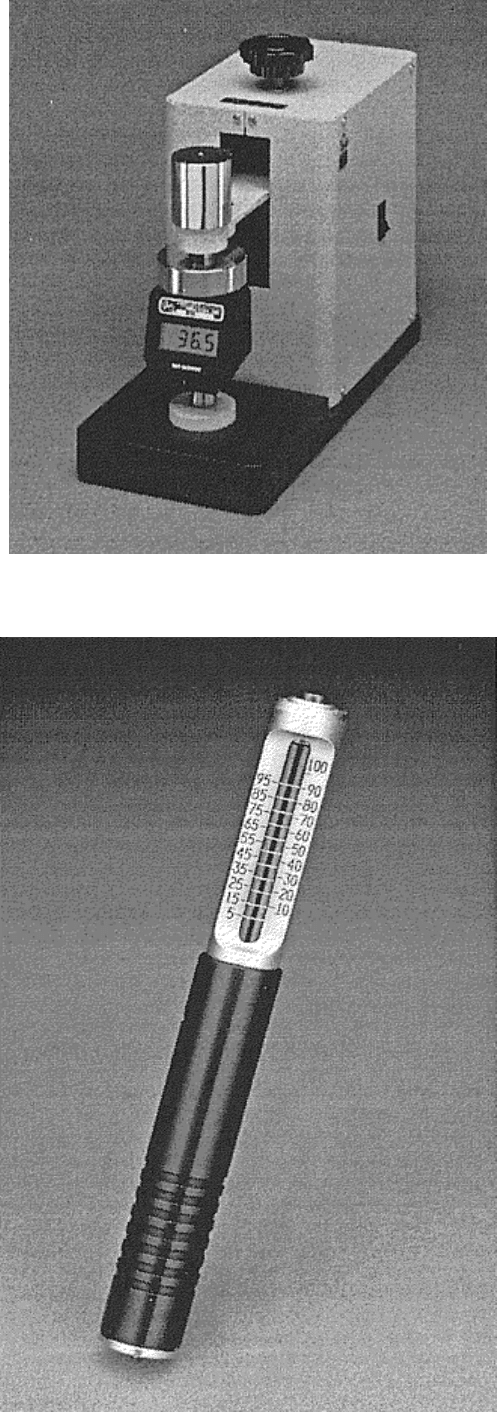
Fig. 5 Digital durometer with stand
Fig. 6 Pencil durometer hardness tester
The total measurement range is from 0 to 100 points. This represents a total travel of the indenter of 2.5 mm
(0.10 in.) for all scales except the M scale, which is 1.25 mm (0.05 in.). The hardness numbers are typically
displayed in increments that vary from five points for the quadrant and pencil styles, to one point for the round,
and in tenths of a point on digital units.
The M scale is relatively new and was developed to test O-rings. Testing small round sections down to 1.25
mm (0.05 in.) is possible with the M scale. This is possible because of a smaller spring load and shorter depth
of penetration. Because of the increased sensitivity, M scale units can only be used in a stand. Normally, the
stand is equipped with an alignment fixture to properly align the round samples with the indenter. Proper
alignment is critical to obtain accurate results.
Testing Procedure. Test specimens should have a minimum thickness of at least 6 mm (0.2 in.) (1.25 mm, or
0.05 in., for the M scale), unless it is known that identical results are obtained on thinner specimens. Thinner
specimens may be stacked to obtain an indicative reading.
Readings should not be taken on an uneven, irregular, or coarsely grained surface. Round or cylindrical
surfaces, such as rubber rollers, can be tested by “rocking” the durometer on the convex surface and observing
the maximum reading that is attained when the indenter is aligned with the axis of the roller.
Application pressure should be sufficient to ensure firm contact between the flat bottom of the durometer and
the test specimen; the reading should be taken within 1 s after firm contact has been established. However, after
attaining an initially high reading, the dial hand may gradually recede on specimens exhibiting cold flow or
creep characteristics (such as nitrile rubber stock). In such instances, both the instantaneous, or maximum,
reading and the reading after a specified time interval—for example, 10 or 15 s—should be recorded.
Testing Results. Durometer hardness numbers, although arbitrary, have an inverse relationship to indentation by
the indenter. For example, a reading of 30 on the type A durometer on a soft rubber roller indicates an indenter
indentation of 1.8 mm (0.07 in.). Similarly, a reading of 90 on a neoprene faucet washer indicates an indenter
indentation of 0.25 mm (0.01 in.). The use of the durometer at the extreme ends of the scale (below 20 and
above 90) is not recommended. Materials reading above 90 on the type A scale should be tested with the type D
durometer. Materials reading below 20 on the type D scale should be tested with a type A durometer.
One of the most common causes of disagreement in readings among operators is variation in the speed with
which the durometer is applied to the elastomer. For example, in testing a high-creep nitrile rubber, if the
durometer is applied too rapidly to the test specimen, an erroneously high reading is initially attained, with the
dial hand dropping as the durometer is held in contact. At the other extreme, the durometer may be applied too
slowly, causing a significant percentage of indenter penetration to occur before the presser foot of the
durometer is in flush contact with the test specimen, resulting in an inaccurately low reading.
Disagreement can also occur when an insufficient number of tests have been made. Reporting the average of
five readings gives the best results. Tests on a particular material should all be run at the same temperature.
Proper spacing must be allowed between the test point and the edge of the sample.
Scale Relationships. It should be noted that there is no fixed relationship between the test results from the
different scales. A hardness reading of 50 on the A scale is not the same hardness as a 50 reading on the M or
any other scale.
Durometer Calibration. Durometers frequently are equipped with a metal or rubber test block, which enables
the user to ascertain whether the durometer is operating properly at one point on the scale (usually 60
durometer). The metal test block consists of a flat piece of metal with a blind hole on its top surface. When the
presser foot is held against the top surface with the indenter in the blind hole, the durometer reading should
agree with the hardness number stamped on the side of the block, within plus or minus one point. Rubber test
blocks are simply tested like a sample and the result compared to the certificate.
A correct reading on the test block does not mean that the durometer is in calibration. The only way to
accurately verify the durometer is to directly measure the loads applied over the full range for a given indicating
device, indenter extension, and indenter shape. Calibrations of this type are recommended annually.
A durometer calibrating device is also available. This mechanism has limited capabilities and is recommended
for end users who have several durometers to monitor. The durometer may be returned to the manufacturer for
periodic inspection and calibration.
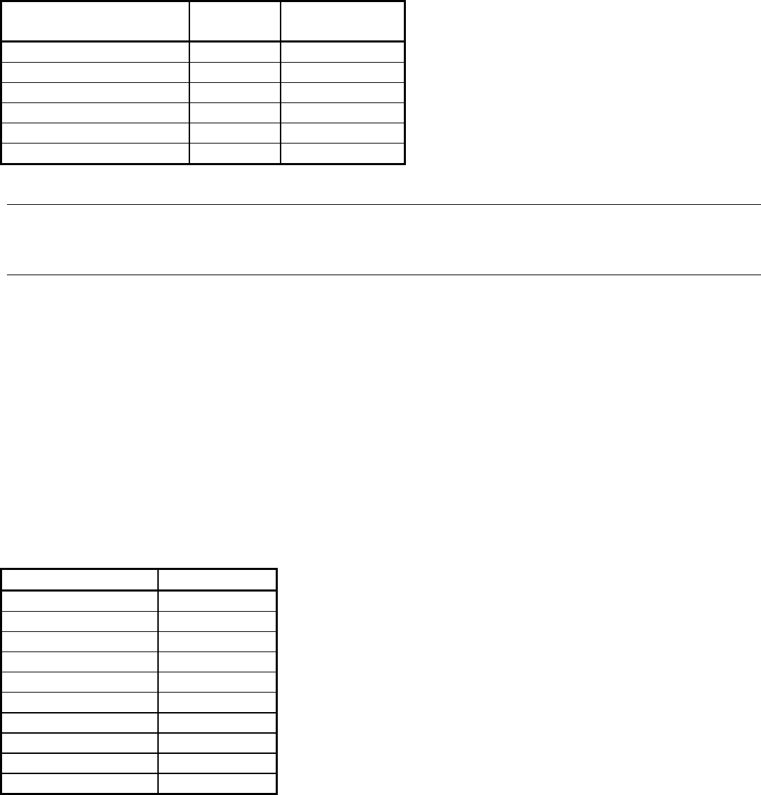
Auxiliary Equipment. The operating stand (Fig. 7) is designed to enable absolutely flush application of the
durometer to the test specimen, thus eliminating errors in readings due to out-of-perpendicular contact. The
stand is intended primarily for testing specimens with parallel opposite sides (except for the M-scale stands that
provide a means to align O-rings). Additional weights are frequently applied to the top of the stands (see the
tester setup on the right side of Fig. 7). The higher load on the presser foot can greatly improve the repeatability
of the results. Operating stands normally provide some means to ensure constant velocity and constant load
applications. This helps to eliminate user error due to too rapid or too slow an application, as discussed earlier.
Fig. 7 Durometer hardness testers mounted in operating stands
Miscellaneous Hardness Tests
Edward L. Tobolski, Wilson Instrument Division, Instron Corporation
IRHD Rubber Hardness Testing
International rubber hardness degrees (IRHD) testing is very similar to durometer testing with some important
differences. Durometer testers apply a load to the sample using a calibrated spring and a pointed or blunt-
shaped indenter. The load, therefore, will vary according to the depth of the indentation because of the spring
gradient. The IRHD tester uses a minor-major load system of constant load and a ball indenter to determine the
hardness of the sample. In the procedure, the minor load is applied to the sample through the ball indenter.
After 5 s, the depth-measuring system is set to zero. The higher major load is then applied. After 30 s, the
IRHD hardness number is read from the depth-measuring indicator.
Testers. The instruments used for IRHD testing look very similar to the durometer testers described in the
previous section. The IRHD tester cannot be used as a handheld instrument due to the requirements to apply the
minor and major loads accurately. Therefore, all IRHD units have a built-in stand to hold the indicator and
loading mechanism. The presser foot size and load applied to it during the test are critical to the final results.
Applications. IRHD testers come in two different versions, standard and micro (see Table 4) and are capable of
testing a range of soft elastomers. The standard units are intended to test flat parallel samples thicker than 4 mm
(0.16 in.). Microtesters can test parts as thin as 1 mm (0.04 in.) and are used to test O-rings or other curved
samples. A maximum of two layers of material may be used to reach the minimum thickness requirements. The
test spacing and edge-clearance requirements for IRHD testing are similar to those of durometer testing.
Table 4 Comparison of standard and micro IRHD hardness testers
Parameter Standard
testers
Microtesters
Diam of ball, mm 2.50 ± 0.01
0.395 ± 0.005
Minor force on ball, N 0.29 ± 0.02
0.0083 ± 0.0005
Major force on ball, N 5.4 ± 0.01
0.1455 ± 0.0005
Total force on ball, N 5.7 ± 0.03
0.153 ± 0.001
Outside diam of foot, mm
6 ± 1
1.00 ± 0.15
Force on foot, N 8.3 ± 1.5 0.235 ± 0.03
Miscellaneous Hardness Tests
Edward L. Tobolski, Wilson Instrument Division, Instron Corporation
Scratch Hardness Tests
Scratch hardness tests represent the oldest type of hardness evaluation procedures. The two most common
techniques for measuring scratch hardness are the Mohs scale, which is used for testing minerals, and the file
hardness test, which is used for testing steels.
A third type of scratch hardness test sometimes referred to as the “plowing test” is not discussed in detail in this
article. This test measures the width of a scratch made by drawing a diamond indenter across the surface under
a definite load. Loads on the indenter of 1, 2, 5, 10, and 25 g are commonly used. This is a useful tool for
studying the relative hardness of microconstituents, but it does not lend itself to high reproducibility or extreme
accuracy. For more information, see the article “Scratch Testing” in this Volume.
The Mohs scale of hardness was devised in 1822 by German mineralogist Friedrich Mohs. The Mohs scale
consists of ten minerals arranged in order from 1 (softest) to 10 (hardest). Each mineral in the scale will scratch
all those below it:
Mineral
Hardness index
Diamond
10
Corundum
9
Topaz
8
Quartz
7
Orthoclase (feldspar)
6
Apatite
5
Fluorite
4
Calcite
3
Gypsum
2
Talc 1
The steps between numbers on the scale are not of equal value; for example, the difference in hardness between
9 and 10 is much greater than between 1 and 2. To determine the hardness of a mineral, it must be determined
which of the standard materials the unknown will scratch. The hardness will lie between two points on the
scale, the point between the mineral, which may be scratched, and the next one harder.
Materials engineers and metallurgists find little use for the Mohs scale due to its nonquantitative nature.
However, the hardness of iron with 0.1% carbon maximum is between 3 and 4 on the Mohs scale, and copper is
between 2 and 3. Fully hardened high-carbon tool steel is between 7 and 8.

The file hardness test was one of the first scratch tests used for evaluating the hardness of metallic materials.
The file test is useful in estimating the hardness of steels in the high hardness ranges. It provides information on
soft spots and decarburization quickly and easily and is readily adaptable to odd shapes and sizes that are
difficult to test by other methods.
Standard test files are heat treated to approximately 67 to 70 HRC. The flat face of the file is pressed firmly
against, and slowly drawn across, the surface to be tested. If the file does not bite, the material is designated as
file hard. A number of factors, such as pressure, speed, angle of contact, and surface roughness, influence the
results of the test. Consequently, its ability to give reproducible hardness values is rather limited, and
reasonable accuracy is obtained only at the highest hardness levels.
Miscellaneous Hardness Tests
Edward L. Tobolski, Wilson Instrument Division, Instron Corporation
Ultrasonic Microhardness Testing
Ultrasonic microhardness testing offers an alternative to the more conventional methods based on visual
(microscopic) evaluation of an indentation after the load has been removed. Ultrasonic testing uses a maximum
indentation load of approximately 800 gf. Therefore, as in other microhardness techniques, the indentation
depth is relatively small (from 4 to 18 μm). In the vast majority of instances, the workpiece surface is
unharmed, thus classifying this test as nondestructive. Measured values in either the Vickers or Rockwell C
scale are displayed on a digital readout display directly after penetration of the test piece. This feature renders
the method suitable for automated on-line testing. Up to 1200 parts/h can be tested.
In ultrasonic microhardness testing, a Vickers diamond is attached to one end of a magnetostrictive metal rod.
The diamond-tipped rod is excited to its natural frequency by a piezoelectric converter. The resonant frequency
of the rod changes as the free end of the rod is brought into contact with the surface of a solid body. Once the
device is calibrated for the known modulus of elasticity of the tested material, the area of contact between the
diamond tip and the tested surface can be derived from the measured resonant frequency. The area of contact is
inversely proportional to the hardness of the tested material, provided the force pressing the surface is constant.
Consequently, the measured frequency value can be converted into the corresponding hardness number.
Components of an ultrasonic hardness tester are shown schematically in Fig. 8. The hardness number is
displayed on a digital readout, while the oscillating rod is retracted to protect it until the next reading. The
entire process generally takes less than 15 s. This type of instrument is quite small and can be battery powered
for portability. The automatic probe allows hardness measurements to be made in any orientation, further
enhancing its usefulness. By means of a probe and suitably designed fixtures for holding the probe, the
possibilities are virtually unlimited. For example, Fig. 9 shows the test point, fixture, and actual testing of fillet
radii on an engine crankshaft. In this instance, it was possible to take ten readings/min.
