ASM Metals HandBook Vol. 8 - Mechanical Testing and Evaluation
Подождите немного. Документ загружается.

Many standards, such as ASTM A 370, E 8, and B 557, provide guidance in the selection of test-piece
orientation relative to the rolling direction of the plate or the major forming axes of other types of products and
in the selection of specimen and test-piece location relative to the surface of the product. Orientation is also
important when characterizing the directionality of properties that often develops in the microstructure of
materials during processing. For example, some causes of directionality include the fibering of inclusions in
steels, the formation of crystallographic textures in most metals and alloys, and the alignment of molecular
chains in polymers.
The location from which a test material is taken from the initial product form is important because the manner
in which a material is processed influences the uniformity of microstructure along the length of the product as
well as through its thickness properties. For example, the properties of metal cut from castings are influenced
by the rate of cooling and by shrinkage stresses at changes in section. Generally, test pieces taken from near the
surface of iron castings are stronger. To standardize test results relative to location, ASTM A 370 recommends
that tension test pieces be taken from midway between the surface and the center of round, square, hexagon, or
octagonal bars. ASTM E 8 recommends that test pieces be taken from the thickest part of a forging from which
a test coupon can be obtained, from a prolongation of the forging, or in some cases, from separately forged
coupons representative of the forging.
Test-Piece Geometry
As previously noted, the item being tested may be either the full cross section of the item or a portion of the
item that has been machined to specific dimensions. This article focuses on tension testing with test pieces that
are machined from rough samples. Component testing is discussed in more detail in the article “Mechanical
Testing of Fiber Reinforced Composites” in this Volume.
Test-piece geometry is often influenced by product form. For example, only test pieces with rectangular cross
sections can be obtained from sheet products. Test pieces taken from thick plate may have either flat (plate-
type) or round cross sections. Most tension-test specifications show machined test pieces with either circular
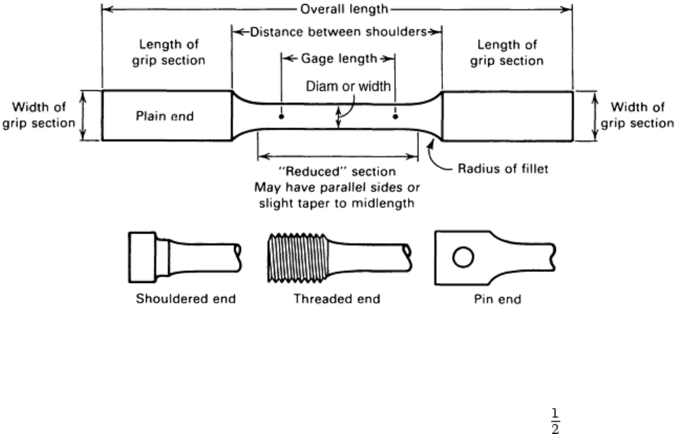
cross sections or rectangular cross sections. Nomenclature for the various sections of a machined test piece are
shown in Fig. 21. Most tension-test specifications present a set of dimensions, for each cross-section type, that
are standard, as well as additional sets of dimensions for alternative test pieces. In general, the standard
dimensions published by ASTM, ISO, JIS, and DIN are similar, but they are not identical.
Fig. 21 Nomenclature for a typical tension test piece
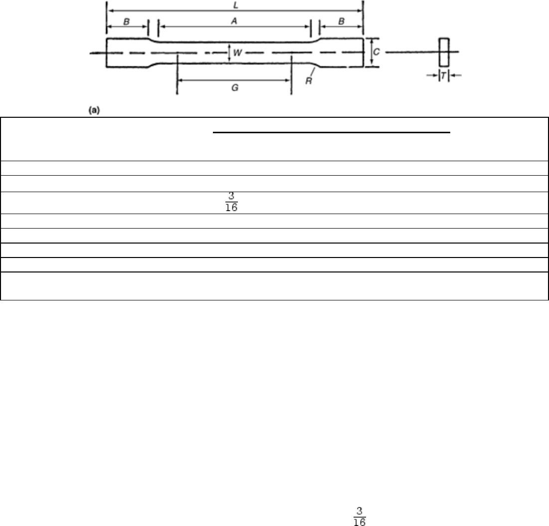
Gage lengths and standard dimensions for machined test pieces specified in ASTM E 8 are shown in Fig. 22 for
rectangular and round test pieces. From this figure, it can be seen that the gage length is proportionally four
times (4 to 1) the diameter (or width) of the test piece for the standard machined round test pieces and the sheet-
type, rectangular test pieces. The length of the reduced section is also a minimum of 4 times the diameter (or
width) of these test-piece types. These relationships do not apply to plate-type rectangular test pieces.
Standard specimens, in.
Plate type, 1½ in.
wide
Sheet type, ½in.
wide
Subsize
specimen,
¼in. wide, in.
G, gage length
(a)(b)
8.00 ± 0.01 2.00 ± 0.005 1.000 ± 0.003
W, width
(c)(d)
1½ + ⅛–¼
0.500 ± 0.010 0.250 ± 0.005
T, thickness
(e)
<
0.005 ≤ T ≤ ¾ 0.005 ≤ T ≤ ¼
R, radius of fillet, min
(f)
1 ½ ¼
L, overall length, min
(b)(g)
18 8 4
A, length of reduced section, min
9 2¼ 1¼
B, length of grip section, min
(h)
3 2 1¼
C, width of grip section,
approximate
(d)(i)
2 ¾
⅜
Note:
(a) For the 1½ in. wide specimen, punch marks for measuring elongation after fracture shall be made on the flat
or on the edge of the specimen and within the reduced section. Either a set of nine or more punch marks 1 in.
apart or one or more pairs of punch marks 8 in. apart may be used.
(b) When elongation measurements of 1½ in. wide specimens are not required, a minimum length of reduced
section (A) of 2¼ in. may be used with all other dimensions similar to those of the plate-type specimen.
(c) For the three sizes of specimens, the ends of the reduced section shall not differ in width by more than
0.004, 0.002, or 0.001 in., respectively. Also, there may be a gradual decrease in width from the ends to the
center, but the width at each end shall not be more than 0.015, 0.005, or 0.003 in., respectively, larger than the
width at the center.
(d) For each of the three sizes of specimens, narrower widths (W and C) may be used when necessary. In such
cases the width of the reduced section should be as large as the width of the material being tested permits;
however, unless stated specifically, the requirements for elongation in a product specification shall not apply
when these narrower specimens are used.
(e) The dimension T is the thickness of the test specimen as provided for in the applicable material
specifications. Minimum thickness of 1½ in. wide specimens shall be in. Maximum thickness of ½in. and
¼in. wide specimens shall be ¾in. and ¼in., respectively.
(f) For the 1½ in. wide specimen, a ½in. minimum radius at the ends of the reduced section is permitted for
steel specimens under 100,000 psi in tensile strength when a profile cutter is used to machine the reduced
section.
(g) To aid in obtaining axial force application during testing of ¼in. wide specimens, the overall length should
be as large as the material will permit, up to 8.00 in.
(h) It is desirable, if possible, to make the length of the grip section large enough to allow the specimen to
extend into the grips a distance equal to two-thirds or more of the length of the grips. If the thickness of ½in.
wide specimens is over ⅜in., longer grips and correspondingly longer grip sections of the specimen may be
necessary to prevent failure in the grip section.
(i) For the three sizes of specimens, the ends of the specimen shall be symmetrical in width with the enter line
of the reduced section within 0.10, 0.05, and 0.005 in., respectively. However, for referee testing and when
required by product specifications, the ends of the ½in. wide specimen shall be symmetrical within 0.01 in.
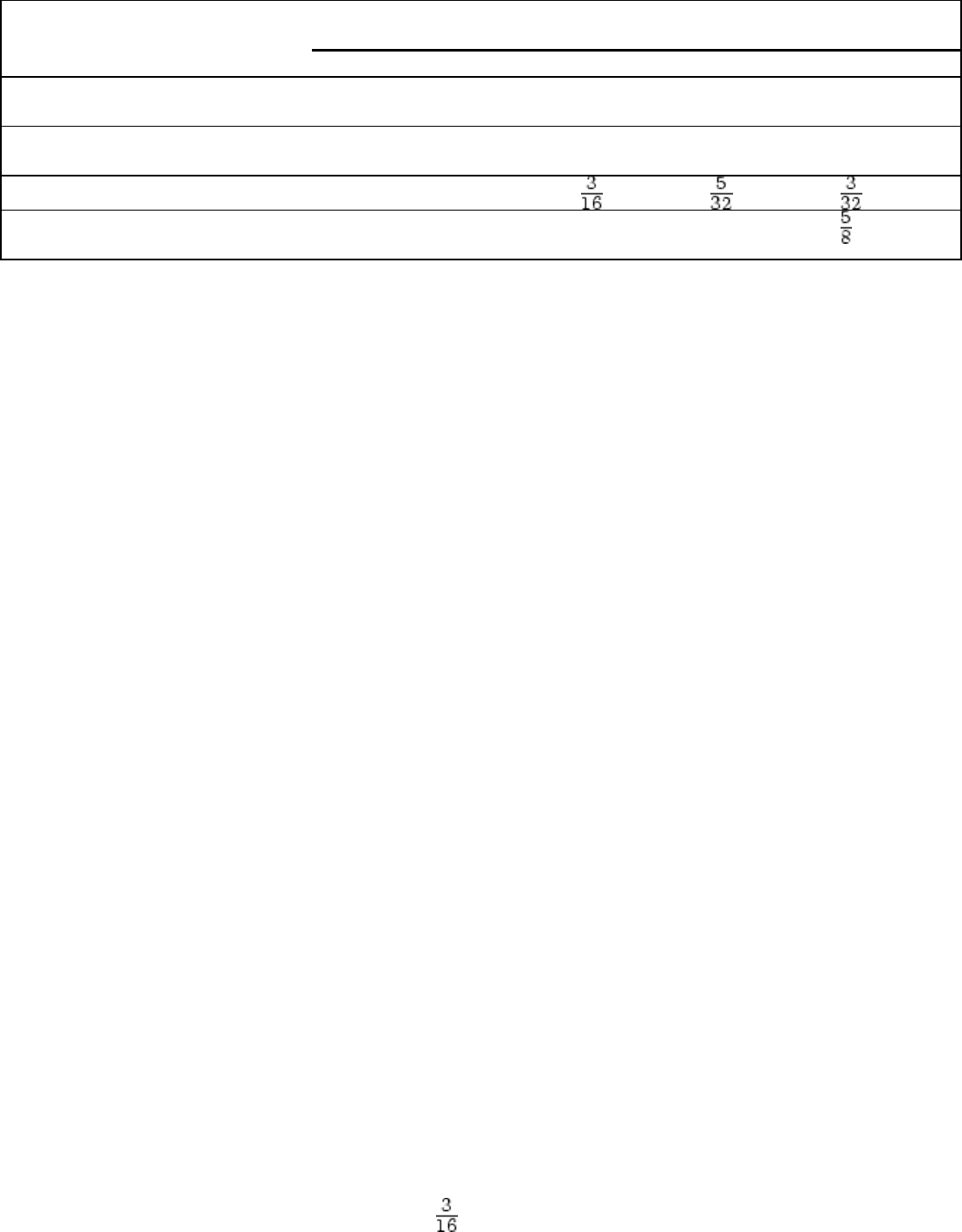
Fig. 22 Examples of tension test pieces per ASTM E 8. (a) Rectangular (flat) test pieces.
(b) Round test-piece
Standard specimen, in.,
at nominal diameter:
Small-size specimens proportional to
standard, in., at nominal diameter:
0.500 0.350 0.250 0.160 0.113
G, gage length
2.000 ±
0.005
1.400 ±
0.005
1.000 ±
0.005
0.640 ±
0.005
0.450 ±
0.005
D, diameter
(a)
0.500 ±
0.010
0.350 ±
0.007
0.250 ±
0.005
0.160 ±
0.003
0.113 ±
0.002
R, radius of fillet, min
⅜
¼
A, length of reduced section,
min
(b)
2¼ 1¾ 1¼ ¾
Note:
(a) The reduced section may have a gradual taper from the ends toward the center, with the ends not more than
1% larger in diameter than the center (controlling dimension).
(b) If desired, the length of the reduced section may be increased to accommodate an extensometer of any
convenient gage length. Reference marks for the measurement of elongation should, nevertheless, be spaced at
the indicated gage length.
Fig. 22
Many specifications outside the United States require that the gage length of a test piece be a fixed ratio of the
square root of the cross-sectional area, that is:
Gage length = constant x (cross-sectional area)
1/2
The value of this constant is often specified as 5.65 or 11.3 and applies to both round and rectangular test
pieces. For machined round test pieces, a value of 5.65 results in a 5-to-1 relationship between the gage length
and the diameter.
Many tension-test specifications permit a slight taper toward the center of the reduced section of machined test
pieces so that the minimum cross section occurs at the center of the gage length and thereby tends to cause
fracture to occur at the middle of the gage length. ASTM E 8-99 specifies that this taper cannot exceed 1% and
requires that the taper is the same on both sides of the midlength.
When test pieces are machined, it is important that the longitudinal centerline of the reduced section be
coincident with the longitudinal centerlines of the grip ends. In addition, for the rectangular test pieces, it is
essential that the centers of the transition radii at each end of the reduced section are on common lines that are
perpendicular to the longitudinal centerline. If any of these requirements is violated, bending will occur, which
may affect test results.
The transition radii between the reduced section and the grip ends can be critical for test pieces from materials
with very high strength or with very little ductility or both. This is discussed more fully in the section “Effect of
Strain Concentrations” in this article.
Measurement of Initial Test-Piece Dimensions. Machined test pieces are expected to meet size specifications,
but to ensure dimensional accuracy, each test piece should be measured prior to testing. Gage length, fillet
radius, and cross-sectional dimensions are measured easily. Cylindrical test pieces should be measured for
concentricity. Maintaining acceptable concentricity is extremely important in minimizing unintended bending
stresses on materials in a brittle state.
Measurement of Cross-Sectional Dimensions. The test pieces must be measured to determine whether they
meet the requirements of the test method. Test-piece measurements must also determine the initial cross-
sectional area when it is compared against the final cross section after testing as a measure of ductility.
The precision with which these measurements are made is based on the requirements of the test method, or if
none are given, on good engineering judgment. Specified requirements of ASTM E 8 are summarized as
follows:
• For referee testing of test pieces under in. in their least dimension, the dimensions should be
measured where the least cross-sectional area is found.
• For cross sectional dimensions of 0.200 in. or more, cross-sectional dimensions should be measured and
recorded to the nearest 0.001 in.
• For cross sectional dimensions from 0.100 in. but less than 0.200 in., cross-sectional dimensions should
be measured and recorded to the nearest 0.0005 in.
• For cross sectional dimensions from 0.020 in. but less than 0.100 in., cross-sectional dimensions should
be measured and recorded to the nearest 0.0001 in.
• When practical, for cross-sectional dimensions less than 0.020 in., cross-sectional dimensions should be
measured to the nearest 1%, but in all cases, to at least the nearest 0.0001 in.
ASTM E 8 goes on to state how to determine the cross-sectional area of a test piece that has a nonsymmetrical
cross section using the weight and density. When measuring dimensions of the test piece, ASTM E 8 makes no
distinction between the shape of the cross section for standard test pieces.
Measurement of the Initial Gage Length. ASTM E 8 assumes that the initial gage length is within specified
tolerance; therefore, it is necessary only to verify that the gage length of the test piece is within the tolerance.
Marking Gage Length. As shown in the flow diagram in Fig. 18, measurement of elongation requires marking
the gage length of the test piece. The gage marks should be placed on the test piece in a manner so that when
fracture occurs, the fracture will be located within the center one-third of the gage length (or within the center
one-third of one of several sets of gage-length marks). For a test piece machined with a reduced-section length
that is the minimum specified by ASTM E 8 and with a gage length equal to the maximum allowed for that
geometry, a single set of marks is usually sufficient. However, multiple sets of gage lengths must be applied to
the test piece to ensure that one set spans the fracture under any of the following conditions:
• Testing full-section test pieces
• Testing pieces with reduced sections significantly longer than the minimum
• Test requirements specify a gage length that is significantly shorter than the reduced section
For example, some product specifications require that the elongation be measured over a 2 in. gage length using
the machined plate-type test piece with a 9 in. reduced section (Fig. 22a). In this case, it is recommended that a
staggered series of marks (either in increments of 1 in. when testing to ASTM E 8 or in increments of 25.0 mm
when testing to ASTM E 8M) be placed on the test piece such that, after fracture, the elongation can be
measured using the set that best meets the center-third criteria. Many tension-test methods permit a retest when
the elongation is less than the minimum specified by a product specification if the fracture occurred outside the
center third of the gage length. When testing full-section test pieces and determining elongation, it is important
that the distance between the grips be greater than the specified gage length unless otherwise specified. As a
rule of thumb, the distance between grips should be equal to at least the gage length plus twice the minimum
dimension of the cross section.
The gage marks may be marks made with a center punch, or may be lines scribed using a sharp, pointed tool,
such as a machinist's scribe (or any other means that will establish the gage length within the tolerance
permitted by the test method). If scribed lines are used, a broad line or band may first be drawn along the length
of the test piece using machinist's layout ink (or a similar substance), and the gage marks are made on this line.
This practice is especially helpful to improve visibility of scribed gage marks after fracture. If punched marks
are used, a circle around each mark or other indication made by ink may help improve visibility after fracture.
Care must be taken to ensure that the gage marks, especially those made using a punch, are not deep enough to
become stress raisers, which could cause the fracture to occur through them. This precaution is especially
important when testing materials with high strength and low ductility.
Notched Test Pieces. Tension test pieces are sometimes intentionally notched in the center of the gage length
(Fig. 23). ASTM E 338 and E 602 describe procedures for testing notched test pieces. Results obtained using
notched test pieces are useful for evaluating the response of a material to a localized stress concentration.
Detailed information on the notch tensile test and a discussion of the related material characteristics (notch
sensitivity and notch strength) can be found in the article “Mechanical Behavior Under Tensile and
Compressive Loads” in this Volume. The effect of stress (or strain) concentrations is also discussed in the
section “Effect of Strain Concentrations” in this article.
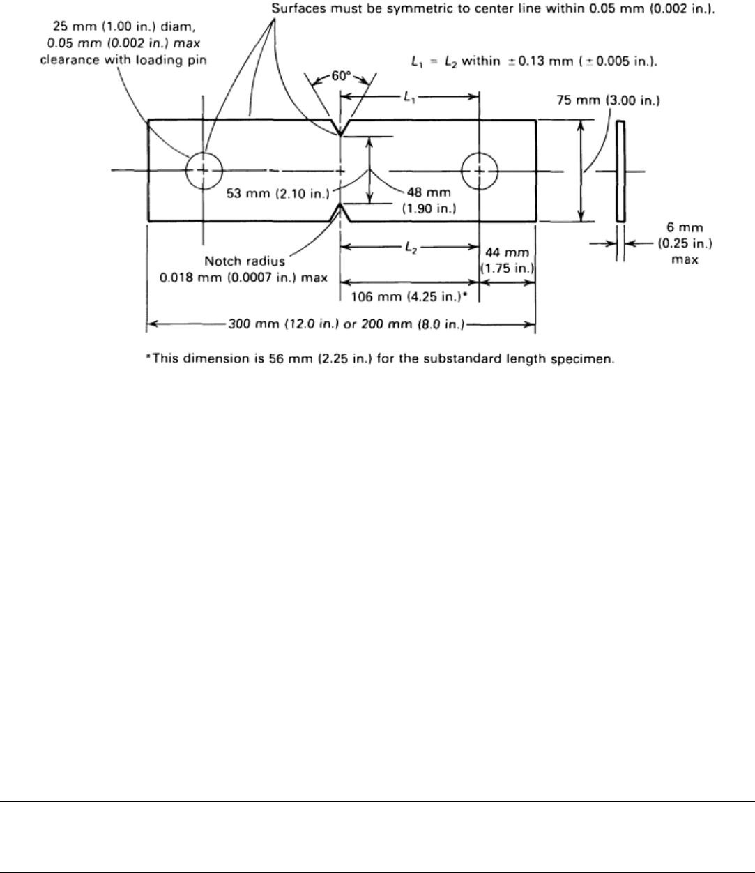
Fig. 23 Example of notched tension-test test piece per ASTM E 338 “Standard Test
Method of Sharp-Notch Tension Testing of High-Strength Sheet Materials”
Surface Finish and Condition. The finish of machined surfaces usually is not specified in generic test methods
(that is, a method that is not written for a specific item or material) because the effect of finish differs for
different materials. For example, test pieces from materials that are not high strength or that are ductile are
usually insensitive to surface finish effects. However, if surface finish in the gage length of a tensile test piece
is extremely poor (with machine tool marks deep enough to act as stress-concentrating notches, for example),
test results may exhibit a tendency toward decreased and variable strength and ductility.
It is good practice to examine the test piece surface for deep scratches, gouges, edge tears, or shear burrs. These
discontinuities may sometimes be minimized or removed by polishing or, if necessary, by further machining;
however, dimensional requirements often may no longer be met after additional machining or polishing. In all
cases, the reduced sections of machined test pieces must be free of detrimental characteristics, such as cold
work, chatter marks, grooves, gouges, burrs, and so on. Unless one or more of these characteristics is typical of
the product being tested, an unmachined test piece must also be free of these characteristics in the portion of the
test piece that is between the gripping devices. When rectangular test pieces are prepared from thin-gage sheet
material by shearing (punching) using a die the shape of the test piece, ASTM E 8 states that the sides of the
reduced section may need to be further machined to remove the cold work and shear burrs that occur when the
test piece is sheared from the rough specimen. This method is impractical for material less than 0.38 mm (0.015
in.) thick. Burrs on test pieces can be virtually eliminated if punch-to-die clearances are minimized.
Uniaxial Tension Testing
John M. (Tim) Holt, Alpha Consultants and Engineering
Test Setup
The setup of a tensile test involves the installation of a test piece in the load frame of a suitable test machine.
Force capacity is the most important factor of a test machine. Other test machine factors, such as calibration and
load-frame rigidity, are discussed in more detail in the article “Testing Machines and Strain Sensors” in this
Volume. The other aspects of the test setup include proper gripping and alignment of the test piece, and the
installation of extensometers or strain sensors when plastic deformation (yield behavior) of the piece is being
measured, as described below.
Gripping Devices. The grips must furnish an axial connection between the test piece and the testing machine;
that is, the grips must not cause bending in the test piece during loading. The choice of grip is primarily
dependent on the geometry of the test piece and, to a lesser degree, on the preference of the test laboratory. That
is, rarely do tension-test methods or requirements specify the method of gripping the test pieces.
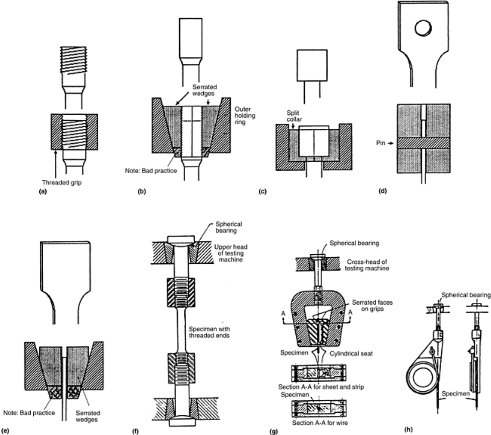
Figure 24 shows several of the many grips that are in common use, but many other designs are also used. As
can be seen, the gripping devices can be classified into several distinct types, wedges, threaded, button, and
snubbing. Wedge grips can be used for almost any test-piece geometry; however, the wedge blocks must be
designed and installed in the machine to ensure axial loading. Threaded grips and button grips are used only for
machined round test pieces. Snubbing grips are used for wire (as shown) or for thin, rectangular test pieces,
such as those made from foil.
Fig. 24 Examples of gripping methods for tension test pieces. (a) Round specimen with
threaded grips. (b) Gripping with serrated wedges with hatched region showing bad
practice of wedges extending below the outer holding ring. (c) Butt-end specimen
constrained by a split collar. (d) Sheet specimen with pin constraints. (e) Sheet specimen
with serrated-wedge grip with hatched region showing the bad practice of wedges
extended below the outer holding ring. (f) Gripping device for threaded-end specimen. (g)
Gripping device for sheet and wire. (h) Snubbing device for testing wire. Sources:
Adapted from Ref 1 and ASTM E 8
As shown in Fig. 22, the dimensions of the grip ends for machined round test pieces are usually not specified,
and only approximate dimensions are given for the rectangular test pieces. Thus, each test lab must
prepare/machine grip ends appropriate for its testing machine. For machined-round test pieces, the grip end is
often threaded, but many laboratories prefer either a plain end, which is gripped with the wedges in the same
manner as a rectangular test piece, or with a button end that is gripped in a mating female grip. Because the
principal disadvantage of a threaded grip is that the pitch of the threads tend to cause a bending moment, a fine-
series thread is often used.
Bending stresses are normally not critical with test pieces from ductile materials. However, for test pieces from
materials with limited ductility, bending stresses can be important, better alignment may be required. Button
grips are often used, but adequate alignment is usually achieved with threaded test pieces. ASTM E 8 also
recommends threaded gripping for brittle materials. The principal disadvantage of the button-end grip is that the
diameter of the button or the base of the cone is usually at least twice the diameter of the reduced section, which
necessitates a larger, rough specimen and more metal removal during machining.
Alignment of the Test Piece. The force-application axis of the gripping device must coincide with the
longitudinal axis of symmetry of the test piece. If these axes do not coincide, the test piece will be subjected to
a combination of axial loading and bending. The stress acting on the different locations in the cross section of
the test piece then varies, from the sum of the axial and bending stresses on one side of the test piece, to the
difference between the two stresses on the other side. Obviously, yielding will begin on the side where the
stresses are additive and at a lower apparent stress than would be the case if only the axial stress were present.
For this reason, the yield stress may be lowered, and the upper yield stress would appear suppressed in test
pieces that normally exhibit an upper yield point. For ductile materials, the effect of bending is minimal, other
than the suppression of the upper yield stress. However, if the material has little ductility, the increased strain
due to bending may cause fracture to occur at a lower stress than if there were no bending.
Similarly, if the test piece is initially bent, for example, coil set in a machined-rectangular cross section or a
piece of rod being tested in a full section, bending will occur as the test piece straightens, and the problems
exist.
Methods for verification of alignment are described in ASTM E 1012.
Extensometers. When the tension test requires the measurement of strain behavior (i.e., the amount of elastic
and/or plastic deformation occurring during loading), extensometers must be attached to the test piece. The
amount of strain can be quite small (e.g., approximately 0.5% or less for elastic strain in steels), and
extensometers and other strain-sensing systems are designed to magnify strain measurement into a meaningful
signal for data processing.
Several types of extensometers are available, as described in more detail in the article “Testing Machines and
Strain Sensors” in this Volume. Extensometers generally have fixed gage lengths. If an extensometer is used
only to obtain a portion of the stress-strain curve sufficient to determine the yield properties, the gage length of
the extensometer may be shorter than the gage length required for the elongation-at-fracture measurement. It
may also be longer, but in general, the extensometer gage length should not exceed approximately 85% of the
length of the reduced section or the distance between the grips for test pieces without reduced sections. National
and international standardization groups have prepared practices for the classification of extensometers, as
described in the article “Testing Machines and Strain Sensors” extensometer classifications usually are based
on error limits of a device, as in ASTM E 83 “Standard Practice for Verification and Classification of
Extensometers.”
Temperature Control. Tension testing is sometimes performed at temperatures other than room temperature.
ASTM E 21 describes standard procedures for elevated-temperature tension testing of metallic materials, which
is described further in the article “Hot Tension and Compression Testing” in this Volume. Currently, there is no
ASTM standard procedure for cryogenic testing; further information is contained in the article “Tension and
Compression Testing at Low Temperatures” in this Volume.
Temperature gradients may occur in temperature-controlled systems, and gradients must be kept within
tolerable limits. It is not uncommon to use more than one temperature-sensing device (e.g., thermocouples)
when testing at other than room temperature. Besides the temperature-sensing device used in the control loop,
auxiliary sensing devices may be used to determine whether temperature gradients are present along the gage
length of the test piece.
Temperature control is also a factor during room-temperature tests because deformation of the test piece causes
generation of heat within it. Test results have shown that the heating that occurs during the straining of a test
piece can be sufficient to significantly change the properties that are determined because material strength
typically decreases with an increase in the test temperature. When performing a test to duplicate the results of
others, it is important to know the test speed and whether any special procedures were taken to remove the heat
generated by straining the test piece.
Reference cited in this section
1. D. Lewis, Tensile Testing of Ceramics and Ceramic-Matrix Composites, Tensile Testing, P. Han, Ed.,
ASM International, 1992, p 147–182
Uniaxial Tension Testing
John M. (Tim) Holt, Alpha Consultants and Engineering
Test Procedures
After the test piece has been properly prepared and measured and the test setup established, conducting the test
is fairly routine. The test piece is installed properly in the grips, and if required, extensometers or other strain-
measuring devices are fastened to the test piece for measurement and recording of extension data. Data
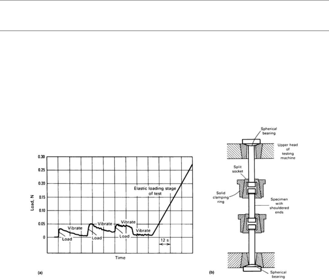
acquisition systems also should be checked. In addition, it is sometimes useful to repetitively apply small initial
loads and vibrate the load train (a metallographic engraving tool is a suitable vibrator) to overcome friction in
various couplings, as shown in Fig. 25(a). A check can also be run to ensure that the test will run at the proper
testing speed and temperature. The test is then begun by initiating force application.

Fig. 25(a) Effectiveness of vibrating the load train to overcome friction in the spherical
ball and seat couplings shown in (b). (b) Spherically seated gripping device for shouldered
tension test piece.
Speed of Testing
The speed of testing is extremely important because mechanical properties are a function of strain rate, as
discussed in the section “Effect of Strain Rate” in this article. It is, therefore, imperative that the speed of
testing be specified in either the tension-test method or the product specification.
In general, a slow speed results in lower strength values and larger ductility values than a fast speed; this
tendency is more pronounced for lower-strength materials than for higher-strength materials and is the reason
that a tension test must be conducted within a narrow test-speed range.
In order to quantify the effect of deformation rate on strength and other properties, a specific definition of
testing speed is required. A conventional (quasi-static) tension test, for example, ASTM E 8, prescribes upper
and lower limits on the deformation rate, as determined by one of the following methods during the test:
• Strain rate
• Stress rate (when loading is below the proportional limit)
• Cross-head separation rate (or free-running cross-head speed) during the test
• Elapsed time
These methods are listed in order of decreasing precision, except during the occurrence of upper-yield-strength
behavior and yield point elongation (YPE) (where the strain rate may not necessarily be the most precise
method). For some materials, elapsed time may be adequate, while for other materials, one of the remaining
methods with higher precision may be necessary in order to obtain test values within acceptable limits. ASTM
E 8 specifies that the test speed must be slow enough to permit accurate determination of forces and strains.
Although the speeds specified by various test methods may differ somewhat, the test speeds for these methods
are roughly equivalent in commercial testing.
Strain rate is expressed as the change in strain per unit time, typically expressed in units of min
-1
or s
-1
because
strain is a dimension-less value expressed as a ratio of change in length per unit length. The strain rate can
usually be dialed, or programmed, into the control settings of a computer-controlled system or paced or timed
for other systems.
Stress rate is expressed as the change in stress per unit of time. When the stress rate is stipulated, ASTM E 8
requires that it not exceed 100 ksi/ min. This number corresponds to an elastic strain rate of about 5 × 10
-5
s
-1
for steel or 15 × 10
-5
s
-1
for aluminum. As with strain rate, stress rate usually can be dialed or programmed into
the control settings of computer-controlled test systems. However, because most older systems indicate force
being applied, and not stress, the operator must convert stress to force and control this quantity. Many machines
are equipped with pacing or indicating devices for the measurement and control of the stress rate, but in the
absence of such a device, the average stress rate can be determined with a timing device by observing the time
required to apply a known increment of stress. For example, for a test piece with a cross section of 0.500 in. by
0.250 in. and a specified stress rate of 100,000 psi/min, the maximum force application rate would be 12,500
lbf/min (force = stress rate × area = 100,000 psi/min × (0.500 in. × 0.250 in.)). A minimum rate of of the
maximum rate is usually specified.
Comparison between Strain-Rate and Stress-Rate Methods. Figure 26 compares strain-rate control with stress-
rate control for describing the speed of testing. Below the elastic limit, the two methods are identical. However,
as shown in Fig. 26, once the elastic limit is exceeded, the strain rate increases when a constant stress rate is
applied. Alternatively, the stress rate decreases when a constant strain rate is specified. For a material with
discontinuous yielding and a pronounced upper yield spike (Fig. 7a), it is a physical impossibility for the stress
rate to be maintained in that region because, by definition, there is not a sustained increase in stress in this
region. For these reasons, the test methods usually specify that the rate (whether stress rate or strain rate) is set
prior to the elastic limit (EL), and the crosshead speed is not adjusted thereafter. Stress rate is not applicable
beyond the elastic limit of the material. Test methods that specify rate of straining expect the rate to be
controlled during yield; this minimizes effects on the test due to testing machine stiffness.
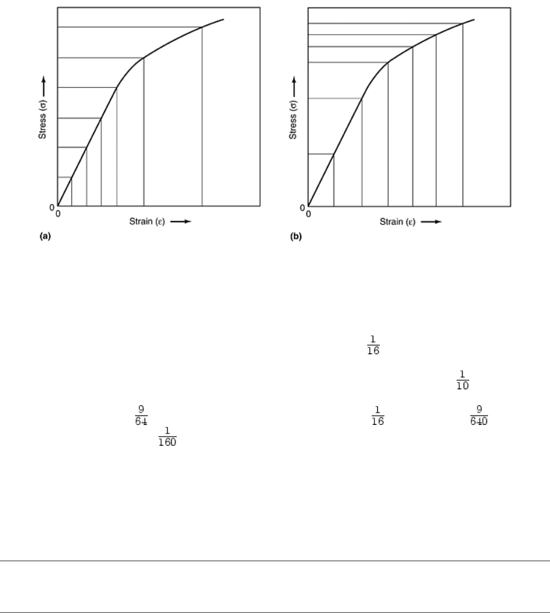
Fig. 26 Illustration of the differences between constant stress increments and constant
strain increments. (a) Equal stress increments (increasing strain increments). (b) Equal
strain increments (decreasing stress increments)
The rate of separation of the grips (or rate of separation of the cross heads or the cross-head speed) is a
commonly used method of specifying the speed of testing. In ASTM A 370, for example, the specification of
test speed is that “through the yield, the maximum speed shall not exceed in. per inch of reduced section per
minute; beyond yield or when determining tensile strength alone, the maximum speed shall not exceed ½in. per
inch of reduced section per minute. For both cases, the minimum speed shall be greater than of this amount.”
This means that for a machined round test piece with a 2¼ in. reduced section, the rate prior to yielding can
range from a maximum of in./min (i.e., 2¼ in. reduced-section length × in./min) down to in./min (i.e.,
2¼ in. reduced-section length × in./min).
The elapsed time to reach some event, such as the onset of yielding or the tensile strength, or the elapsed time
to complete the test, is sometimes specified. In this case, multiple test pieces are usually required so that the
correct test speed can be determined by trial and error.
Many test methods permit any speed of testing below some percentage of the specified yield or tensile strength
to allow time to adjust the force application mechanism, ensure that the extensometer is working, and so on.
Values of 50 and 25%, respectively, are often used.
Uniaxial Tension Testing
John M. (Tim) Holt, Alpha Consultants and Engineering
Post-Test Measurements
After the test has been completed, it is often required that the cross-sectional dimensions again be measured to
obtain measures of ductility. ASTM E 8 states that measurements made after the test shall be to the same
accuracy as the initial measurements.
Method E 8 also states that upon completion of the test, gage lengths 2 in. and under are to be measured to the
nearest 0.01 in., and gage lengths over 2 in. are to be measured to the nearest 0.5%. The document goes on to
state that a percentage scale reading to 0.5 % of the gage length may be used. However, if the tension test is
