ASM Metals HandBook Vol. 8 - Mechanical Testing and Evaluation
Подождите немного. Документ загружается.


• Engineering stress,s: The force at any time during the test divided by the initial area of the test piece; s
= F/A
0
where F is the force, and A
0
is the initial cross section of a test piece.
• True stress, σ: The force at any time divided by the instantaneous area of the test piece; σ = F/A
i
where
F is the force, and A
i
is the instantaneous cross section of a test piece.
Because an increasing force stretches a test piece, thus decreasing its cross-sectional area, the value of true
stress will always be greater than the nominal, or engineering, stress.
These two definitions of stress are further related to one another in terms of the strain that occurs when the
deformation is assumed to occur at a constant volume (as it frequently is). As previously noted, strain can be
expressed as either engineering strain (e) or true strain, where the two expressions of strain are related as ε =
ln(1 + e). When the test-piece volume is constant during deformation (i.e., A
i
L
i
= A
0
L
0
), then the instantaneous
cross section, A
i
, is related to the initial cross section, A
0
, where
A = A
0
exp {-ε}
= A
0
/(1 + e)
If these expressions for instantaneous and initial cross sections are divided into the applied force to obtain
values of true stress (at the instantaneous cross section, A
i
) and engineering stress (at the initial cross section,
A
0
), then:
σ = s exp {ε} = s (1 + e)
Typically, engineering stress is more commonly considered during uniaxial tension tests. All discussions in this
article are based on nominal engineering stress and strain unless otherwise noted. More detailed discussions on
true stress and true strain are in the article “Mechanical Behavior under Tensile and Compressive Loads” in this
Volume.
Uniaxial Tension Testing
John M. (Tim) Holt, Alpha Consultants and Engineering
Stress-Strain Behavior
During a tension test, the force applied to the test piece and the amount of elongation of the test piece are
measured simultaneously. The applied force is measured by the test machine or by accessory force-measuring
devices. The amount of stretching (or extension) can be measured with an extensometer. An extensometer is a
device used to measure the amount of stretch that occurs in a test piece. Because the amount of elastic stretch is
quite small at or around the onset of yielding (in the order of 0.5% or less for steels), some manner of
magnifying the stretch is required. An extensometer may be a mechanical device, in which case the
magnification occurs by mechanical means. An extensometer may also be an electrical device, in which case
the magnification may occur by mechanical means, electrical means, or by a combination of both.
Extensometers generally have fixed gage lengths. If an extensometer is used only to obtain a portion of the
stress-strain curve sufficient to determine the yield properties, the gage length of the extensometer may be
shorter than the gage length required for the elongation-at-fracture measurement. It may also be longer, but in
general, the extensometer gage length should not exceed approximately 85 to 90% of the length of the reduced
section or of the distance between the grips for test pieces without reduced sections. This ratio for some of the
most common test configurations with a 2 in. gage length and 2 in. reduced section is 0.875%.
The applied force, F, and the extension, ΔL, are measured and recorded simultaneously at regular intervals, and
the data pairs can be converted into a stress-strain diagram as shown in Fig. 2. The conversion from force-
extension data to stress-strain properties is shown schematically in Fig. 2(a). Engineering stress, s, is obtained
by dividing the applied force by the original cross-sectional area, A
0
, of the test piece, and strain, e, is obtained
by dividing the amount of extension, ΔL, by the original gage length, L. The basic result is a stress-strain curve
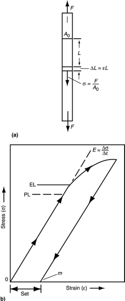
(Fig. 2b) with regions of elastic deformation and permanent (plastic) deformation at stresses greater than those
of the elastic limit (EL in Fig. 2b).
Fig. 2 Stress-strain behavior in the region of the elastic limit. (a) Definition of σ and ε in
terms of initial test piece length, L, and cross-sectional area, A
0
, before application of a
tensile force, F. (b) Stress-strain curve for small strains near the elastic limit (EL)
Typical stress-strain curves for three types of steels, aluminum alloys, and plastics are shown in Fig. 3 (Ref 3).
Stress-strain curves for some structural steels are shown in Fig. 4(a) (Ref 4) for elastic conditions and for small
amounts of plastic deformation. The general shape of the stress-strain curves can be described for deformation
in this region. However, as plastic deformation occurs, it is more difficult to generalize about the shape of the
stress-strain curve. Figure 4(b) shows the curves of Fig. 4(a) continued to fracture.
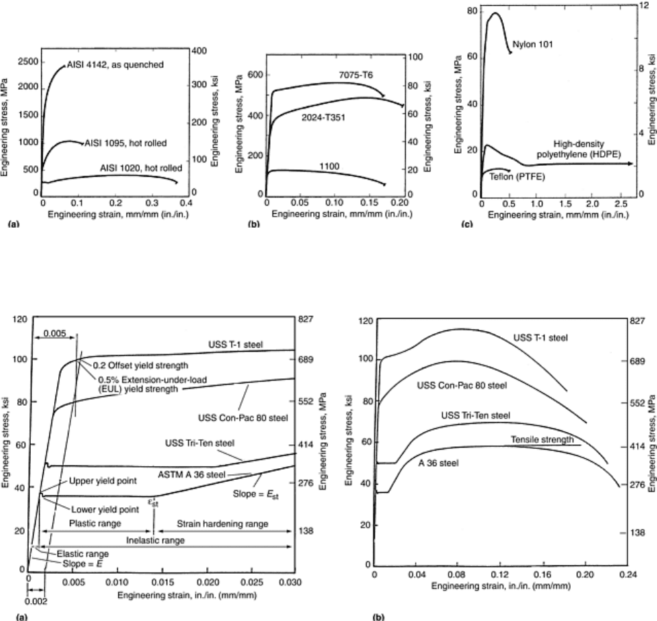
Fig. 3 Typical engineering stress-strain curves from tension tests on (a) three steels, (b)
three aluminum alloys, and (c) three plastics. PTFE, polytetrafluoroethylene. Source: Ref
3
Fig. 4 Typical stress-strain curves for structural steels having specified minimum tensile
properties. (a) Portions of the stress-strain curves in the yield-strength region. (b) Stress-
strain curves extended through failure. Source: Ref 4
Elastic deformation occurs in the initial portion of a stress-strain curve, where the stress-strain relationship is
initially linear. In this region, the stress is proportional to strain. Mechanical behavior in this region of stress-
strain curve is defined by a basic physical property called the modulus of elasticity (often abbreviated as E).
The modulus of elasticity is the slope of the stress-strain line in this linear region, and it is a basic physical
property of all materials. It essentially represents the spring constant of a material.
The modulus of elasticity is also called Hooke's modulus or Young's modulus after the scientists who
discovered and extensively studied the elastic behavior of materials. The behavior was first discovered in the
late 1600s by the English scientist Robert Hooke. He observed that a given force would always cause a
repeatable, elastic deformation in all materials. He further discovered that there was a force above which the
deformation was no longer elastic; that is, the material would not return to its original length after release of the
force. This limiting force is called the elastic limit (EL in Fig. 2b). Later, in the early 1800s, Thomas Young, an
English physicist, further investigated and described this elastic phenomenon, and so his name is associated
with it.
The proportional limit (PL) is a point in the elastic region where the linear relationship between stress and strain
begins to break down. At some point in the stress-strain curve (PL in Fig. 2b), linearity ceases, and small
increase in stress causes a proportionally larger increase in strain. This point is referred to as the proportional
limit (PL) because up to this point, the stress and strain are proportional. If an applied force below the PL point
is removed, the trace of the stress and strain points returns along the original line. If the force is reapplied, the
trace of the stress and strain points increases along the original line. (When an exception to this linearity is
observed, it usually is due to mechanical hysteresis in the extensometer, the force indicating system, the
recording system, or a combination of all three.)
The elastic limit (EL) is a very important property when performing a tension test. If the applied stresses are
below the elastic limit, then the test can be stopped, the test piece unloaded, and the test restarted without
damaging the test piece or adversely affecting the test results. For example, if it is observed that the
extensometer is not recording, the force-elongation curve shows an increasing force, but no elongation. If the
force has not exceeded the elastic limit, the test piece can be unloaded, adjustments made, and the test restarted
without affecting the results of the test. However, if the test piece has been stressed above the EL, plastic
deformation (set) will have occurred (Fig. 2b), and there will be a permanent change in the stress-strain
behavior of the test piece in subsequent tension (or compression) tests.
The PL and the EL are considered identical in most practical instances. In theory, however, the EL is
considered to be slightly higher than the PL, as illustrated in Fig. 2b. The measured values of EL or PL are
highly dependent on the magnification and sensitivity of the extensometer used to measure the extension of the
test piece. In addition, the measurement of PL and EL also highly depends on the care with which a test is
performed.
Plastic Deformation (Set) from Stresses above the Elastic Limit. If a test piece is stressed (or loaded) and then
unloaded, any retest proceeds along the unloading path whether or not the elastic limit was exceeded. For
example, if the initial stress is less than the elastic limit, the load-unload-reload paths are identical. However, if
a test piece is stressed in tension beyond the elastic limit, then the unload path is offset and parallel to the
original loading path (Fig. 2b). Moreover, any subsequent tension measurements will follow the previous
unload path parallel to the original stress-strain line. Thus, the application and removal of stresses above the
elastic limit affect all subsequent stress-strain measurements.
The term set refers to the permanent deformation that occurs when stresses exceed the elastic limit (Fig. 2b).
ASTM E 6 defines set as the strain remaining after the complete release of a load-producing deformation.
Because set is permanent deformation, it affects subsequent stress-strain measurements whether the reloading
occurs in tension or compression. Likewise, permanent set also affects all subsequent tests if the initial loading
exceeds the elastic limit in compression. Discussions of these two situations follow.
Reloading after Exceeding the Elastic Limit in Tension. If a test piece is initially loaded in tension beyond the
elastic limit and then unloaded, the unload path is parallel to the initial load path but offset by the set; on
reloading in tension, the unloading path will be followed. Figure 5 illustrates a series of stress-strain curves
obtained using a machined round test piece of steel. (The strain axis is not to scale.) In this figure, the test piece
was loaded first to Point A and unloaded. The area of the test piece was again determined (A
2
) and reloaded to
Point B and unloaded. The area of the test piece was determined for a third time (A
3
) and reloaded until fracture
occurred. Because during each loading the stresses at Points A and B were in excess of the elastic limit, plastic
deformation occurred. As the test piece is elongated in this series of tests, the cross-sectional area must decrease
because the volume of the test piece must remain constant. Therefore, A
1
> A
2
> A
3
.
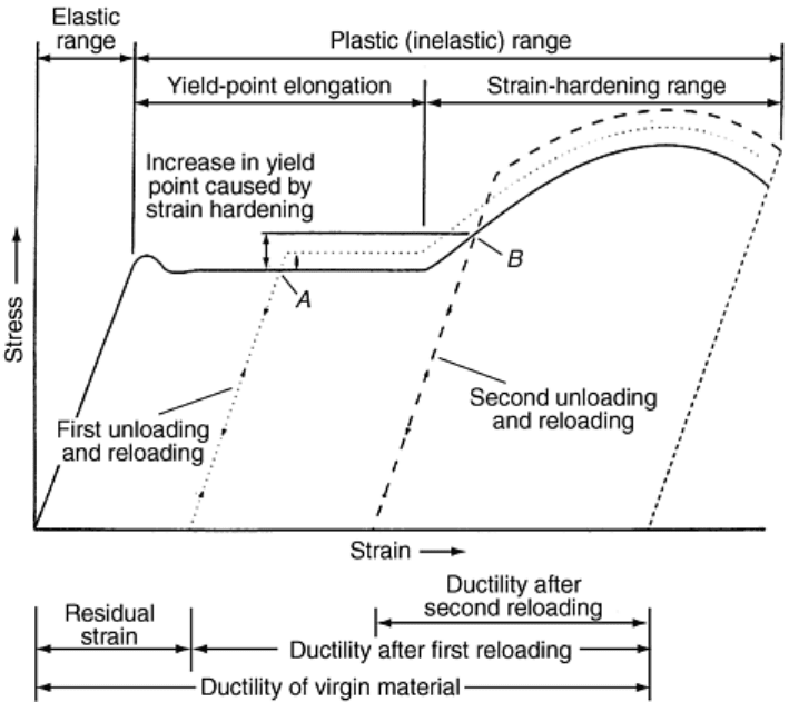
Fig. 5 Effects of prior tensile loading on tensile stress-strain behavior. Solid line, stress-
strain curve based on dimensions of unstrained test piece (unloaded and reloaded twice);
dotted line, stress-strain curve based on dimensions of test piece after first unloading;
dashed line, stress-strain curve based on dimensions of test piece after second unloading.
Note: Graph is not to scale.
The curve with a solid line in Fig. 5 is obtained for engineering stresses calculated using the applied forces
divided by the original cross-sectional area. The curve with a dotted line is obtained from stresses calculated
using the applied forces divided by the cross-sectional area, A
2
, with the origin of this stress-strain curve located
on the abscissa at the end point of the first unloading line. The curve represented by the dashed line is obtained
from the stresses calculated using the applied forces divided by the cross-sectional area, A
3
, with the origin of
this stress-strain curve located on the abscissa at the end point of the second unloading line. This figure
illustrates what happens if a test is stopped, unloaded, and restarted. It also illustrates one of the problems that
can occur when testing pieces from material that has been formed into a part (or otherwise plastically strained
before testing). An example is a test piece that was machined from a failed structure to determine the tensile
properties. If the test piece is from a location that was subjected to tensile deformation during the failure, the
properties obtained are probably not representative of the original properties of the material.
Bauschinger Effect. The other loading condition occurs when the test piece is initially loaded in compression
beyond the elastic limit and then unloaded. The unload path is parallel to the initial load path but offset by the
set; on reloading in tension, the elastic limit is much lower, and the shape of the stress-strain curve is
significantly different. The same phenomenon occurs if the initial loading is in tension and the subsequent
loading is in compression. This condition is called the Bauschinger effect, named for the German scientist who
first described it around 1860. Again, the significance of this phenomenon is that if a test piece is machined
from a location that has been subjected to plastic deformation, the stress-strain properties will be significantly
different than if the material had not been so strained. This occurrence is illustrated in Fig. 6, where a machined
round steel test piece was first loaded in tension to about 1% strain, unloaded, loaded in compression to about
1% strain, unloaded, and reloaded in tension. For this steel, the initial portion of tension and compression
stress-strain curves are essentially identical.
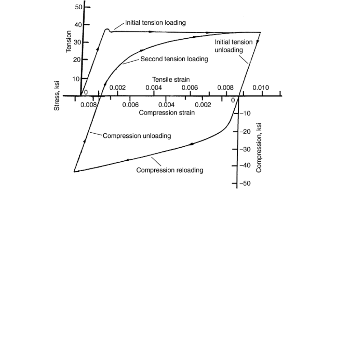
Fig. 6 Example of the Bauschinger effect and hysteresis loop in tension-compression-
tension loading. This example shows initial tension loading to 1% strain, followed by
compression loading to 1% strain, and then a second tension loading to 1% strain.
References cited in this section
3. N.E. Dowling, Mechanical Behavior of Materials—Engineering Methods for Deformation, Fracture,
and Fatigue, 2nd ed., Prentice Hall, 1999, p 123
4. R.L. Brockenbough and B.G. Johnson, “Steel Design Manual,” United States Steel Corporation,
ADUSS 27 3400 03, 1974, p 2–3
Uniaxial Tension Testing
John M. (Tim) Holt, Alpha Consultants and Engineering
Properties from Test Results
A number of tensile properties can be determined from the stress-strain diagram. Two of these properties, the
tensile strength and the yield strength, are described in the next section of this article, “Strength Properties.” In
addition, total elongation (ASTM E 6), yield-point elongation (ASTM E 6), Young's modulus (ASTM E 111),
and the strain-hardening exponent (ASTM E 646) are sometimes determined from the stress-strain diagram.
Other tensile properties include the following:
• Poisson's ratio (ASTM E 132)
• Plastic-strain ratio (ASTM E 517)
• Elongation by manual methods (ASTM E 8)
• Reduction of area
These properties require more information than just the data pairs generating a stress-strain curve. None of
these four properties can be determined from a stress-strain diagram.
Strength Properties
Tensile strength and yield strength are the most common strength properties determined in a tension test.
According to ASTM E 6, tensile strength is calculated from the maximum force during a tension test that is
carried to rupture divided by the original cross-sectional area of the test piece. By this definition, it is a stress
value, although some product specifications define the tensile strength as the force (load) sustaining ability of
the product without consideration of the cross-sectional area. Fastener specifications, for example, often refer to
tensile strength as the applied force (load-carrying) capacity of a part with specific dimensions.
The yield strength refers to the stress at which a small, but measurable, amount of inelastic or plastic
deformation occurs. There are three common definitions of yield strength:
• Offset yield strength
• Extension-under-load (EUL) yield strength
• Upper yield strength (or upper yield point)
An upper yield strength (upper yield point) (Fig. 7a) usually occurs with low-carbon steels and some other
metal systems to a limited degree. Often, the pronounced peak of the upper yield is suppressed due to slow
testing speed or nonaxial loading (i.e., bending of the test piece), metallurgical factors, or a combination of
these; in this case, a curve of the type shown in Fig. 7(b) is obtained. The other two definitions of yield
strength, EUL and offset, were developed for materials that do not exhibit the yield-point behavior shown in
Fig. 7. Stress-strain curves without a yield point are illustrated in Fig. 4(a) for USS Con-Pac 80 and USS T-1
steels. To determine either the EUL or the offset yield strength, the stress-strain curve must be determined
during the test. In computer-controlled testing systems, this curve is often stored in memory and may not be
charted or displayed.
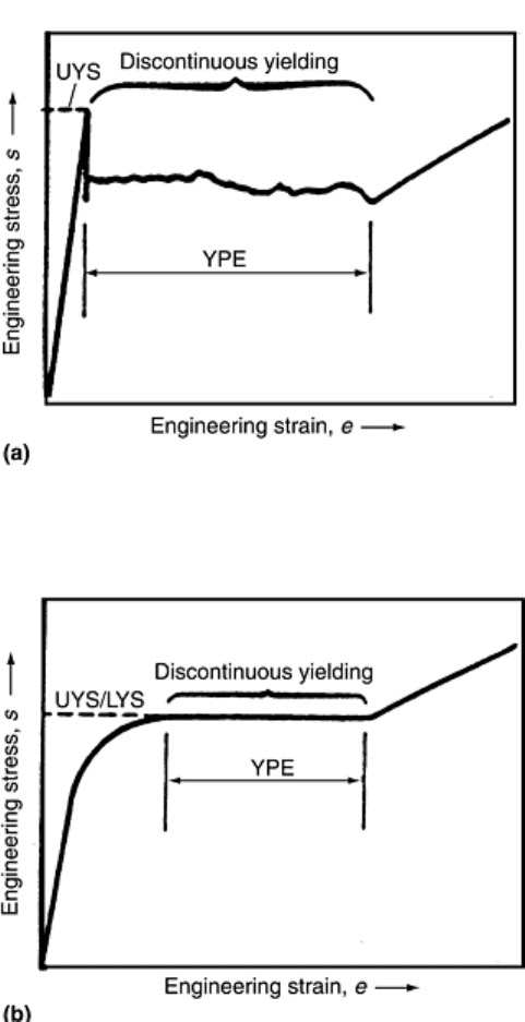
Fig. 7 Examples of stress-strain curves exhibiting pronounced yield-point behavior.
Pronounced yielding, of the type shown, is usually called yield-point elongation (YPE). (a)
Classic example of upper-yield-strength (UYS) behavior typically observed in low-carbon
steels with a very pronounced upper yield strength. (b) General example of pronounced
yielding without an upper yield strength. LYS, lower yield strength
Upper yield strength (or upper yield point) can be defined as the stress at which measurable strain occurs
without an increase in the stress; that is, there is a horizontal region of the stress-strain curve (Fig. 7) where
discontinuous yielding occurs. Before the onset of discontinuous yielding, a peak of maximum stress for
yielding is typically observed (Fig. 7a). This pronounced yielding, of the type shown, is usually called yield-
point elongation (YPE). This elongation is a diffusion-related phenomenon, where under certain combinations
of strain rate and temperature as the material deforms, interstitial atoms are dragged along with dislocations, or
dislocations can alternately break away and be repinned, with little or no increase in stress. Either or both of
these actions cause serrations or discontinuous changes in a stress-strain curve, which are usually limited to the
onset of yielding. This type of yield point is sometimes referred to as the upper yield strength or upper yield
point. This type of yield point is usually associated with low-carbon steels, although other metal systems may
exhibit yield points to some degree. For example, the stress-strain curves for A36 and USS Tri-Ten steels
shown in Fig. 4(a) exhibit this behavior.
The yield point is easy to measure because the increase in strain that occurs without an increase in stress is
visually apparent during the conduct of the test by observing the force-indicating system. As shown in Fig. 7,
the yield point is usually quite obvious and thus can easily be determined by observation during a tension test. It
can be determined from a stress-strain curve or by the halt of the dial when the test is performed on machines
that use a dial to indicate the applied force. However, when watching the movement of the dial, sometimes a
minimum value, recorded during discontinuous yielding, is noted. This value is sometimes referred to as the
lower yield point. When the value is ascertained without instrumentation readouts, it is often referred to as the
halt-of-dial or the drop-of-beam yield point (as an average usually results from eye readings). It is almost
always the upper yield point that is determined from instrument readouts.
Extension-under-load (EUL) yield strength is the stress at which a specified amount of stretch has taken place
in the test piece. The EUL is determined by the use of one of the following types of apparatus:
• Autographic devices that secure stress-strain data, followed by an analysis of this data (graphically or
using automated methods) to determine the stress at the specified value of extension
• Devices that indicate when the specified extension occurs so that the stress at that point may be
ascertained
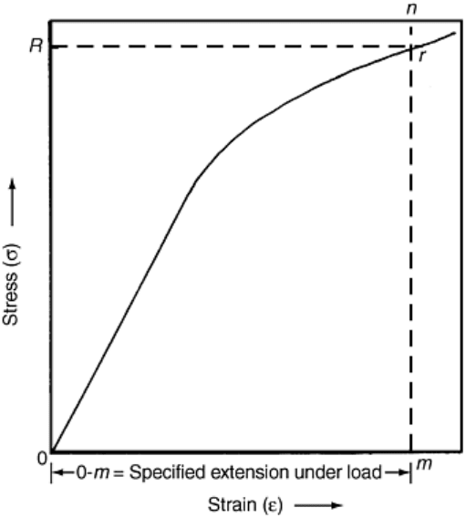
Graphical determination is illustrated in Fig. 8. On the stress-strain curve, the specified amount of extension, 0-
m, is measured along the strain axis from the origin of the curve and a vertical line, m-n, is raised to intersect
the stress-strain curve. The point of intersection, r, is the EUL yield strength, and the value R is read from the
stress axis. Typically, for many materials, the extension specified is 0.5%; however, other values may be
specified. Therefore, when reporting the EUL, the extension also must be reported. For example, yield strength
(EUL = 0.5%) = 52,500 psi is a correct way to report an EUL yield strength. The value determined by the EUL
method may also be termed a yield point.
Fig. 8 Method of determining yield strength by the extension-under-load method (EUL)
(adaptation of Fig. 22 in ASTM E 8)
Offset yield strength is the stress that causes a specified amount of set to occur; that is, at this stress, the test
piece exhibits plastic deformation (set) equal to a specific amount. To determine the offset yield strength, it is
necessary to secure data (autographic or numerical) from which a stress-strain diagram may be constructed
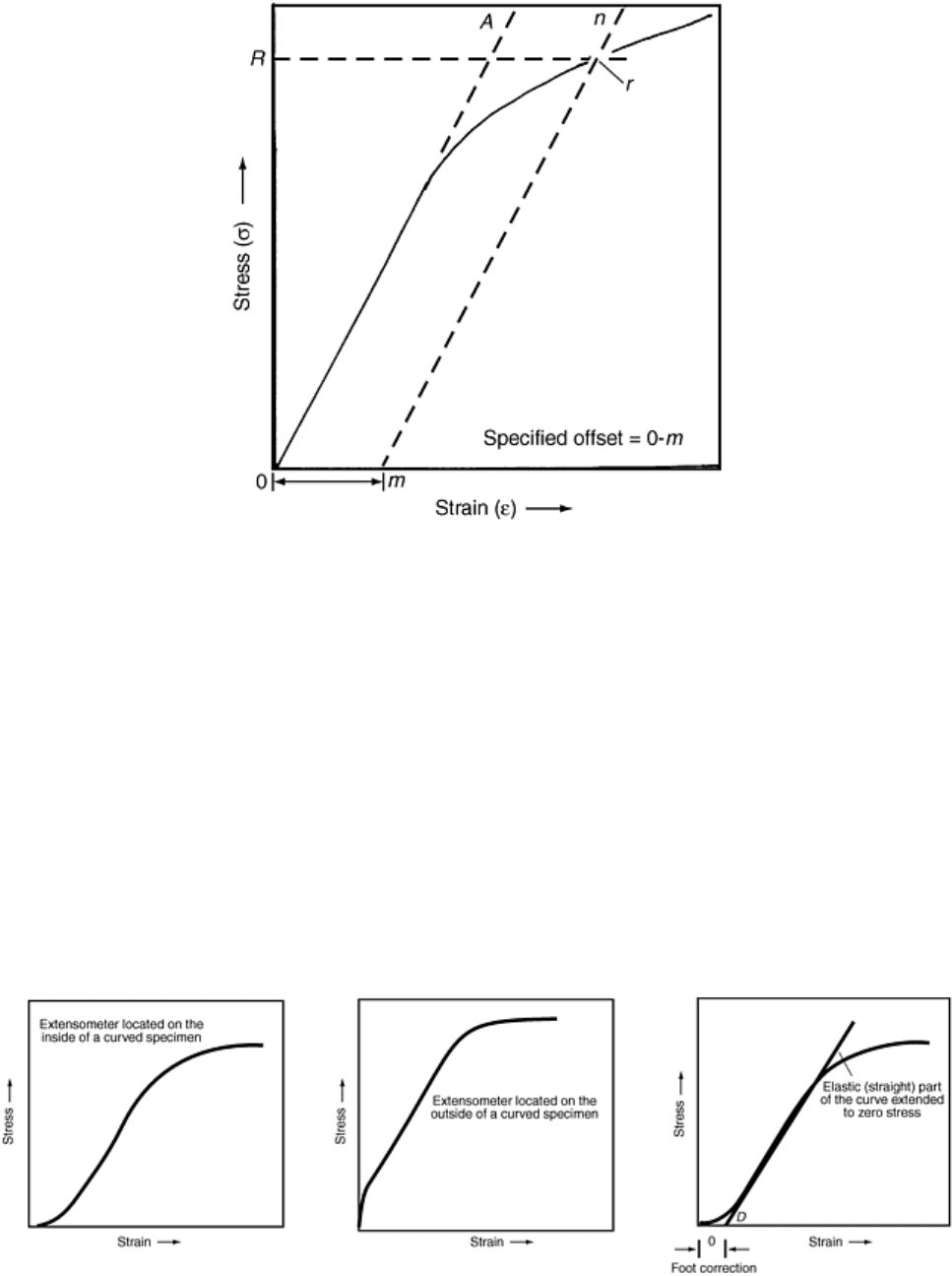
graphically or in computer memory. Figure 9 shows how to use these data; the amount of the specified offset 0-
m is laid out on the strain axis. A line, m-n, parallel to the modulus of elasticity line, 0-A, is drawn to intersect
the stress-strain curve. The point of intersection, r, is the offset yield strength, and the value, R, is read from the
stress axis. Typically, for many materials, the offset specified is 0.2%; however, other values may be specified.
Therefore, when reporting the offset yield strength, the amount of the offset also must be reported; for example,
“0.2 % offset yield strength = 52.8 ksi” or “yield strength (0.2% offset) = 52.8 ksi” are common formats used in
reporting this information.
Fig. 9 Method of determining yield strength by the offset method (adaptation of Fig. 21 in
ASTM E 8)
In Fig. 8 and 9, the initial portion of the stress-strain curve is shown in ideal terms as a straight line.
Unfortunately, the initial portion of the stress-strain curve sometimes does not begin as a straight line but rather
has either a concave or a convex foot (Fig. 10) (Ref 5). The shape of the initial portion of a stress-strain curve
may be influenced by numerous factors such as, but not limited to, the following:
• Seating of the test piece in the grips
• Straightening of a test piece that is initially bent by residual stresses or bent by coil set
• Initial speed of testing
Generally, the aberrations in this portion of the curve should be ignored when fitting a modulus line, such as
that used to determine the origin of the curve. As shown in Fig. 10, a “foot correction” may be determined by
fitting a line, whether by eye or by using a computer program, to the linear portion and then extending this line
back to the abscissa, which becomes point 0 in Fig. 8 and 9. As a rule of thumb, Point D in Fig. 10 should be
less than one-half the specified yield point or yield strength.
