ASM Metals HandBook Vol. 8 - Mechanical Testing and Evaluation
Подождите немного. Документ загружается.

fraction, and void content have to engineering property development in composite systems. This article focuses,
thus, exclusively on measuring the engineering and structural performance of laminates and composite
structures.
Mechanical properties of a composite material refer to the elastic and strength properties of the material under
tensile, shear, or compression loading. Other properties, such as fracture toughness and flexural strength and
stiffness, are also useful in characterizing the performance of a composite material. Finally, thermomechanical
and hydromechanical properties are of importance under changing temperature and moisture environments. The
homogeneity assumption that microstructural features of the material are small enough to be inconsequential to
the average behavior of the material on a macroscale may not apply to composites, especially when strength
and fracture are considered. Fabrics and laminates are very inhomogeneous in character. The scale of
homogeneity of a composite system must be taken into account for fixture design, instrumentation decisions,
and in data analysis.
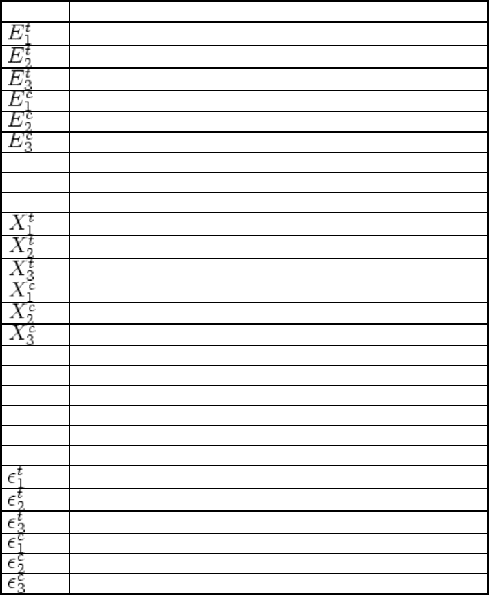
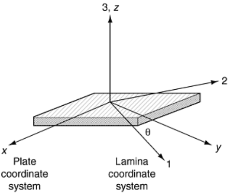
The fundamental description of the engineering properties for a lamina under tension, compression, and shear
loading is given in terms of the lamina coordinate system shown in Fig. 1. The strength and stiffness properties
are defined in Table 1. If the material is transversely isotropic, then the indicated properties need not be
determined. The fracture toughness is sometimes measured as part of durability assessment of a material
system. These properties are the mode I and II critical strain energy release rates (G
Ic
and G
IIc
, respectively).
Flexural properties are also determined routinely and result from bending the material to produce tension,
compression, and shear stresses. The result is more a structural property than an intrinsic material property, but
it is very useful in materials screening and quality control.
Table 1 Listing of mechanical properties typically determined for composite materials
Symbol
Property
Tensile modulus in the fiber direction
Tensile modulus transverse to the fiber
Tensile modulus transverse through the thickness
(a)
Compression modulus in the fiber direction
Compression modulus transverse to the fiber
Compression modulus transverse through the thickness
(a)
G
12
Shear modulus in the 1–2 plane
G
13
Shear modulus in the 1–3 plane
(a)
G
23
Shear modulus in the 2–3 plane
Tensile strength in the fiber direction
Tensile strength transverse to the fiber
Tensile strength through the thickness
(a)
Compression strength in the fiber direction
Compression strength transverse to the fiber
Compression strength through the thickness
(a)
S
12
Shear strength in the 1–2 plane
S
13
Shear strength in the 1–3 plane
(a)
S
23
Shear strength in the 2–3 plane
ν
12
Poisson's ratio in the 1–2 plane
ν
13
Poisson's ratio in the 1–3 plane
ν
23
Poisson's ratio in the 2–3 plane
Ultimate tensile strain in fiber direction
Ultimate tensile strain transverse to the fiber
Ultimate tensile strain through the thickness
(a)
Ultimate compression strain in the fiber direction
Ultimate compression strain transverse to the fiber
Ultimate compression strain through the thickness
(a)
(a) This property does not need to be determined if the 2–3 plane is transversely isotropic.
Fig. 1 Lamina and plate coordinate designation system for composites. Plate coordinates are labeled x, y,
and z. Lamina coordinates are labeled 1, parallel to the fiber axis; 2, perpendicular to the fiber axis; and
3, normal to the fiber plane.
Properties of laminated composites are defined similarly to those for the lamina, except a laminate coordinate
system (x, y, z) is employed. The subscripts 1, 2, 3 on the properties defined in Table 1 are respectively changed
to x, y, and z, and the properties become the effective laminate properties. The word “effective” is very
important because it signifies that the measured response is an average response through the material thickness.
In reality, the stresses in a composite are nonuniform. It should also be noted that composites may behave
differently in compression and tension; the elastic and strength properties must be characterized in both tension
and compression to fully characterize the material.
Role of Specimen Fabrication
The test results from any characterization are critically dependent on material and specimen integrity. Material
processing and specimen machining strongly influence the quality and reproducibility of test results. The
recently issued ASTM D 5687, “Guide for Preparation of Flat Composite Panels with Processing Guidelines for
Specimen Preparation,” provides descriptions of current practices for autoclave processed composites.
Machining of test specimens influences the cost of characterization, and trade-offs must often be weighed
between machining tolerance (program costs) and the requirements on the end use of that data.
Specific specimen geometry and laminate configuration requirements are defined for each test type and are
associated with the discussion of the test methods. Materials for the test specimens are either cast, molded to
shape, pultruded, filament wound, or machined from plaques or plates fabricated using autoclave or other
processing methods. For laminates, a reference edge must be established, and each ply must be oriented
accurately with respect to the reference edge. Before cure, the laminate reference edge is accurately scribed
with a reference line that is used to maintain alignment when the cured plate is trimmed. The fiber volume
fraction, void content, and the uniformity of fiber wetout in the part are controlled by the processing of the test
panel or specimen. All of these factors strongly influence the mechanical properties of the material.
Relationships between processing conditions and material microstructure must be understood and controlled to
produce valid test specimens that are representative of the actual material being characterized (i.e., specimens
that have the same microstructure and properties that the material will have in a structure). The specimen must
be fabricated or machined so that the material axes align properly with the test axes.
Specimen Machining. When fabricated from panels, specimens are normally machined using a diamond wafing
saw. A cut is first made along the reference edge, and then all subsequent cuts are made relative to the reference
edge to preserve the accuracy of the fiber orientation in the panel. When machining specimens to final
geometry, make allowances for scrap, and machine specimens from the heart of the material away from edges.
A diamond saw blade produces a very smooth surface along the cut edges, and no further finishing is required
usually. In specimens requiring holes, a diamond core bit provides satisfactory hole quality. Other methods
include ultrasonic drilling, or drilling with special drill bits in conjunction with templates to guard against
punch-through delamination.
If a specimen is designed to have tabs, the tabs are bonded into place before the specimen is machined to its
final shape. The tab material is typically 3.2 mm (0.13 in.) thick [0/90°] glass/epoxy or a woven fabric
glass/epoxy material, although steel or aluminum can be used. When required, bevels are machined onto the
tab, and then the tab is bonded onto the test panel using special jigs to ensure alignment of the tabs with the
specimen reference edge. Individual specimens are cut from the tabbed panel, again taking care to maintain
alignment with the reference edge (test axis).
Good quality composite specimens should be of uniform dimensions, have a precise fiber alignment, and
possess high-quality finish on machined edges. There should be no evidence of delamination along machined
edges. The laminate should contain no dry fiber regions, voids, or other obvious flaws. If available, ultrasonic
C-scan should be employed to nondestructively evaluate composite panels for flaws prior to specimen
fabrication and testing. Flawed panels or flawed regions within panels should be discarded.
Test Equipment and Fixturing Considerations
The availability of suitable, well-maintained, and accurately calibrated testing equipment is essential for
reliable characterization of composite materials. Standard test instrumentation is used for load introduction and
strain measurement of composite materials, but test fixturing must be specially designed to meet the specific
requirements of the composite tests. The drawings and specifications for standard composite test fixtures are
available for most test standards, and many fixtures are now available commercially. Testing is usually
performed in a screw-driven or a servo-hydraulic universal test machine.
The test machine must have sufficient stiffness and load capacity to insure accurate load application and
deformation measurement. A universal test machine with a load capacity greater than or equal to 110 kN (25 ×
10
3
lbf) is recommended to test composite materials. Longitudinal tension and compression properties of some
composite specimens require this capacity. Fiber tests, transverse tension, and flex properties require much
lower load capacity. Universal test machines allow interchangeability of load cells to accommodate different
testing requirements, and, when needed, small capacity load cells can be used in a 110 kN frame. The load cell
must be properly matched to the loading requirements of the specimen in order to ensure required levels of
accuracy and sensitivity.
Fixturing Issues. Proper fixturing is critically important to composite testing. The special fixtures for each test
are designed to perform two important functions: (a) to transfer loads or displacements from the test machine to
the test specimen, and (b) to achieve load introduction such that the desired stress state and deformation are
produced in the specimen test section. The quality of test results is governed by proper fixture design, accurate
machining to design specifications, and meticulous maintenance of the fixture.
No fixture functions perfectly in generating required states of uniform stress in test specimens; good tests
closely approximate desired stress states and minimize stress concentrations in the test section. Mechanically,
fixtures must provide reproducible alignment of the specimen in the test machine, and specimens should be
easy to insert and remove after testing. The fixture must be strong and stiff enough not to change the
characteristics of the state of stress in the specimen during the test. It must also be constructed of hardened
materials that will not wear excessively with repeated use. Mating surfaces designed to slip relative to each
other must be polished to stringent flatness-finish requirements to minimize friction binding during testing.
Fixture functionality must conform to specifications in all required test environments.
All fixtures should be inspected routinely before testing to ensure that they are not worn or damaged in any way
that will affect the test results. With use, all fixtures wear and eventually decrease the reliability of test results.
Electronic Transducers for Strain Measurement. Strain and deformation measurements are performed on
composites using methods and instruments similar to those used for metals (Ref 4, 5, 6). A few issues must be
addressed when using standard, bondable-foil strain gages on composites.
Gage heating is a problem that must be addressed when using bondable-foil strain gages on polymeric matrix
composites because the polymer does not conduct heat very well. This allows heat to build up in the gage, and
the resulting temperature change causes a resistance change, which is falsely recorded as an apparent strain.
The use of 350 Ω (or greater) strain gages is recommended for composite testing, and the excitation voltage
should be between 2 and 5 V. Measurement sensitivity is related to the excitation voltage, and 2 V is the lowest
voltage that will ensure sufficient sensitivity.
Composites, especially woven fabrics and braided structures, have very coarse microstructure. The size of the
strain-gage grid area must be large enough to average deformation over a representative area of the specimen. If
the material is heterogeneous, such as a woven fabric, the grid must be large enough to cover at least one unit
cell of the structure. A comprehensive discussion of this issue is covered by Masters and Ifju (Ref 6), based on
their extensive survey of experimental results using strain gages of varying size on different types of fabric and
braided composite structures.
The third problem that can occur when using bondable-foil strain gages for testing composites is that transverse
strain sensitivity can influence strain measurements. This is especially prevalent for certain types of angle-ply
lay-ups, such as the [±45°] laminate. Correction factors must be applied to achieve accurate longitudinal
readings measured under such conditions.
Environmental Conditioning
Environmental conditioning is perhaps one of the most controversial aspects of composites testing. It is not just
the temperature at which the material is to be tested that is important. The entire temperature and moisture
histories of the specimen influence the properties. Specimens should be preconditioned before testing by
exposure to the specified temperature and humidity conditions. Specimens to be tested under standard
laboratory conditions (21 ± 1.0°C, 50% ± 20% relative humidity) can be conditioned in the laboratory for a
period of 24 h prior to testing. Specimens designed to evaluate effects of environmental exposure must be
conditioned by using conventional environmental chambers or temperature-controlled baths using the
procedures outlined below.
Moisture conditioning is covered under a relatively new method (ASTM D 5229) and is usually specified in
one of three ways:
• Exposure at a specific temperature and relative humidity or in a water bath to attain a target percentage
weight gain
• Exposure for a specified time duration
• Exposure to attain equilibrium weight gain
Diffusion constants for composites are often very small, and sometimes accelerated conditioning practices are
employed. A specimen can be soaked in water for short durations and attain a certain moisture content instead
of being conditioned for months at 95% relative humidity to attain the same moisture content. Increase of
temperature greatly increases the diffusion rate.
Accelerated conditioning is usually not equivalent to normal conditioning. The aging of the material is a rate
process that depends on path; thus, specimens may not yield the same properties when conditioned using
accelerated processes. Accelerated conditioning is considered a conservative approach, because accelerated
conditioning typically yields larger degradation of properties than tests that are more representative of actual
service conditions.
Prior to conditioning, polymeric matrix composites should ideally be fully characterized using infrared
spectroscopy, thermomechanical analysis, and differential scanning calorimetry to determine the state of cure,
moisture content, and glass transition temperature (T
g
) of the matrix material. This information defines the
preconditioned state of the material. The material can then be subjected to the specified environmental
conditioning regimen. Once conditioned, specimens should again be characterized by analytical equipment.
This is best done on travelers, which are dummy specimens conditioned along with the test specimens for this
purpose. The test specimen cannot be used, since the analytical tests will influence the conditioning of the
specimen and render it useless for testing.
Metal matrix and ceramic matrix composites also have requirements for environmental conditioning. The key
difference is that these types of composites have less sensitivity to moisture uptake, because metallic or ceramic
materials do not exhibit moisture-induced “aging” phenomena.
Analysis of Test Results
Statistical principles should be employed in test program design and analysis of test results (Ref 7). Variability
is normal in all testing, and proper statistical treatment of data ensures that variability is handled properly in
deducing conclusions about the meaning and trends of the measured data. To start, typical variability of a given
test should be used to determine the sample sizes needed to meet statistical significance requirements. Sample
means, medians, and standard deviations are useful but may not be sufficient if the population is not normally
distributed or if variance is large. Analysis of variance techniques may need to be employed to determine
significance in comparisons of results.
Many investigators conduct parametric experiments changing one variable at a time to determine relationships
among experimental variables. This approach results in huge, costly test matrices and often produces poor
results. Design of experiments is a rigorous, statistically based method for testing the relationship of
experimental variables. The design minimizes the number of tests necessary to determine the relationships
between the test variables to a desired level of statistical significance. Consultation with an expert is advised,
since this can save money and produce more reliable results. Several software packages are available to support
statistical analysis and design of experiments.
In any experimental test program, failure modes must be carefully noted. Specimen failures should be the
proper mode for the test being conducted and be consistent. Improper failures are an indication that the test is
poorly designed, the specimen is flawed, or the test fixture or setup is improper. Failed specimens should
always be saved, and typical failures should be photographed and documented.
Footnote
*
The section “Interlaminar Shear Properties of Fiber-
Reinforced Composites at High Strain Rates” was written
by John Harding and Stephen Hallett, Oxford University. The section “Fatigue Testing and Behavior of Fiber-
Reinforced Composites” was written by W. Steven Johnson and Ramesh Talreja, Ge
orgia Institute of
Technology.
References cited in this section
1. R.M. Jones, Mechanics of Composite Materials, 2nd ed., Taylor and Francis, Philadelphia, 1999
2. S.W. Tsai, and H.T. Hahn, Introduction to Composite Materials, Technomic, Lancaster, 1980
3. J.R. Vinson, and T.W. Chou, Composite Materials and Their Use in Structures, Halstead Press, Applied
Science Publishers, Barking, 1975
4. J.M. Whitney, I.M. Daniel, and R.B. Pipes, Experimental Mechanics of Fiber Reinforced Composite
Materials, revised ed., Society for Experimental Mechanics; Prentice-Hall, Englewood Cliffs, 1984
5. R.B. Pipes, Test Methods, Delaware Composites Design Encyclopedia, Vol 6, (L.A. Carlsson and J.W.
Gillespie, Jr., Ed.), Technomic, Lancaster, 1990, p 3
6. J.E. Masters and P.G. Ifju, Strain Gage Selection Criteria for Textile Composite Materials, J. Compos.
Technol. Res., Vol 19 (No. 3), 1997, p 152
7. H.M. Wadsworth, Handbook of Statistical Methods for Engineers and Scientists, McGraw-Hill, New
York, 1990
Mechanical Testing of Fiber-Reinforced Composites
Dale Wilson, The Johns Hopkins University, Leif A. Carlsson, Florida Atlantic University
Characterization of Mechanical Properties
The basic building block of laminated composites is the unidirectional lamina (Fig. 1). Specific test methods are
available to measure lamina mechanical properties. The unidirectional lamina is highly anisotropic, which
complicates mechanical testing. Alignment of the test specimen in the test frame is an important requirement
for obtaining adequate test results, and undesirable transverse failures are a common occurrence in such
materials. For these reasons, a number of investigators propose to back out unidirectional properties from
laminate tests, but no acceptable standards have yet emerged, except for the [±45°] laminate coupon subjected
to uniaxial tension for the generation of lamina shear stress-strain response (ASTM D 3518). There exists a host
of test fixtures, specimen geometries, and test procedures for the generation of mechanical property data for
composite materials. Reviews and further information on the subject are provided in Ref 4, 5, and 8–10. Space
limitations prohibit discussion of each test method. Only test methods accepted by the community as ASTM
standards or as candidates for ASTM standardization are considered in this article. In cases where more than
one method is discussed, the differences are clearly brought out, and guidelines are given about the use of each
method.
Tension Testing
The most basic mechanical test is the tension test. For most structural materials, the tensile properties are
essential elements of the material design allowables. The tension test is used to measure Young's modulus,
Poisson's ratio, tensile strength, and ultimate strain to failure for composites. The properties reduced from
tension tests on composite materials are effective (averaged) properties. The test method applies to
unidirectional composites but can also be performed on laminates, woven fabrics, or discontinuous fiber
composites. For asymmetric and/or unbalanced laminates, extension/bending coupling and extension/shear
coupling effects produce nonuniform stress states in the test section. Under these conditions, effective
properties cannot be accurately determined from the test results using the standard data reduction methods.
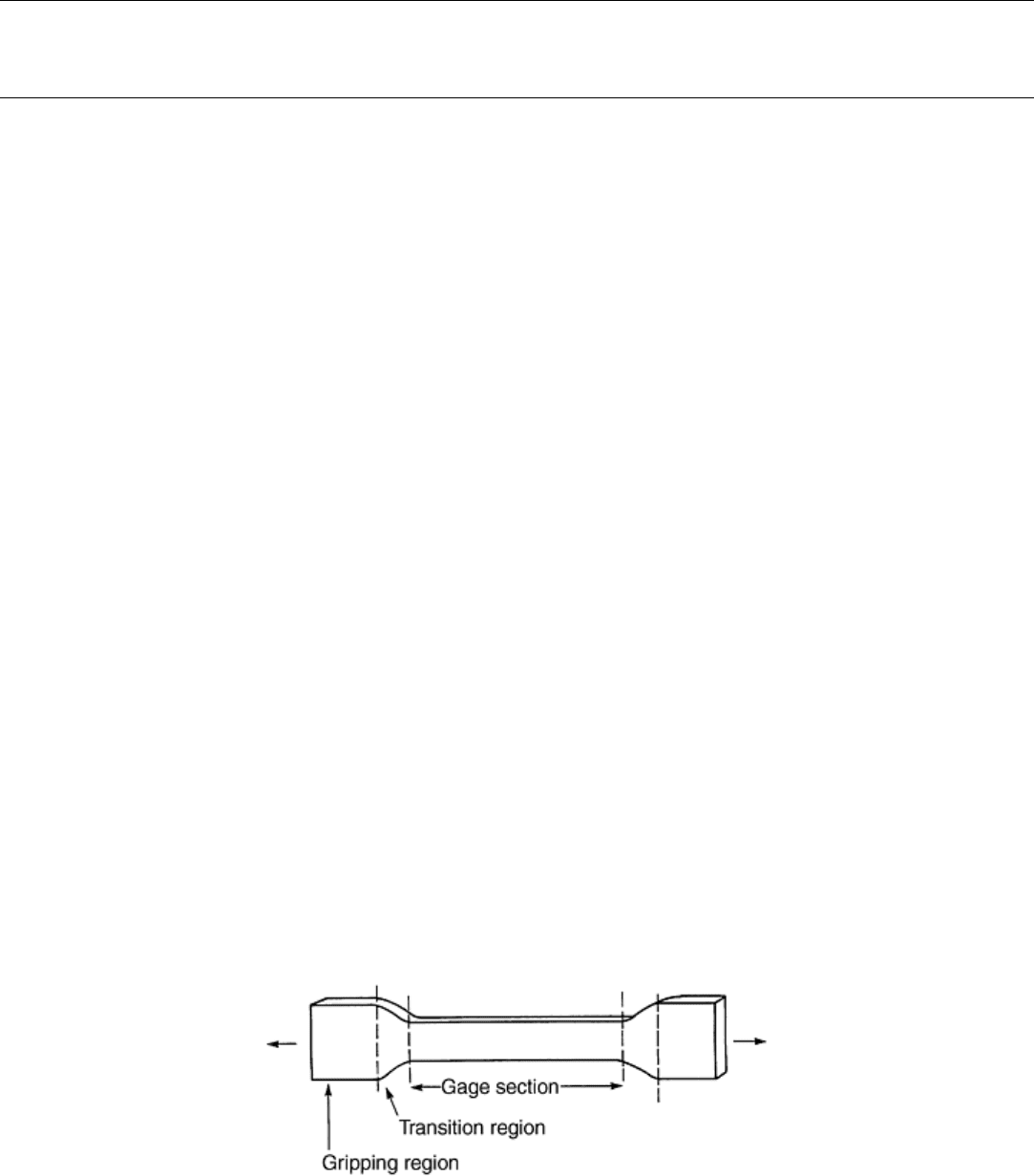
The adequate gripping of the test specimen is the major issue in tension tests. Any tension test specimens (Fig.
2) require gripping regions where loads are introduced through the specimen surfaces, a transition region, and a
gage section region that may be of reduced cross-sectional area to promote failures away from the grips.
Sufficient volume should be involved in the gage section to achieve adequate sampling of the material being
tested.
Fig. 2 Generic tension test specimen
The widthwise tapering popular with metals (Fig. 2) usually leads to splitting failures of highly anisotropic
composites in the gripping region prior to ultimate failure of the material in the gage section. This problem is
avoided by using uniform width (rectangular) test specimens (Ref 10). The grips of the tension test frame
introduce large clamping forces that can cause splitting failures or surface damage in the gripped region. These
forces, coupled with normal stress concentrations induced by load introduction, can lead to anomalous failures.
Tabs with tapered (beveled) ends, therefore, are bonded on each side of the specimen. The load is transferred
into the specimen test section through shear (see Fig. 3). When tabs are used, the properties of the adhesive
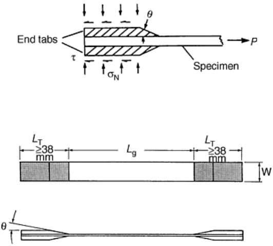
must be carefully chosen to meet the strength and elongation requirements of the composite under the
temperature and moisture conditions imposed by the test. Figure 4 shows the geometry of the ASTM D 3039
tension test specimen. Stress analysis of tabbed specimens (Ref 11, 12) indicates that intense out-of-plane peel
and shear stress exist at the tip of the bevel and that the axial tensile stress in the specimen is increased.
Consequently, tabbed specimens may fail at the tab ends or inside the tabs, but low bevel angles will reduce the
stress concentration (Ref 11). Typically, bevel angles in the range of 15 to 30° are used because tabs with small
taper angles occupy too much of the gage section.
Fig. 3 Load transfer in gripping region of tension test specimen through end tabs
Fig. 4 Specimen for tension testing of composites as defined in ASTM D 3039, L
g
= gage length; L
T
= tab
length; θ = tab bevel angle; w = width
To characterize the tensile response of the unidirectional lamina, 0° and 90° specimens are employed to
determine longitudinal and transverse properties. The [±45°] laminate tension test measures shear properties of
the lamina and is discussed under shear testing. When characterizing multidirectional laminates, the tabs are
sometimes replaced by emery paper inserted between the grips and specimen surface to avoid slippage and
minimize surface damage, but in composite laminates with 0° surface plies, fiber damage is likely to occur in
the gripping region if tabs are not used.
Specimen Machining and Instrumentation. For unidirectional composites of 0° fiber orientation, a specimen
width of 12.7 mm (0.5 in.) and a thickness of 6 plies are common. Unidirectional 90° specimens are typically
25 mm (1 in.) wide and 8 to 16 plies thick. Laminates and sheet molding compound use the same geometry as
the 90° specimen and have the specimen thickness defined by laminate configuration or fundamental sheet
thickness. Loading eccentricity may arise due to variations in tab and specimen thickness. As proposed in
ASTM standard D 3039, tolerances for tab and specimen thicknesses are ±1 and 4%, respectively (Ref 10).
Tabs should be made from [±45°] or [0/90°] glass/epoxy or woven fabric composites. Printed circuit board
(NVF Co., Kennett Square, PA) is often used because of its tight thickness tolerances. Laminates and sheet
molding compound can be tested with or without tabs, although tabs are recommended for thin specimens.
Gage length (L
g
), (Fig. 4) is commonly 125 to 150 mm (5 to 6 in.).
It is common to bond continuous end tabs on the panels prior to machining the specimens. After careful surface
preparation of the bonding surfaces of the specimens and end tabs (Ref 8), the end tabs are attached with an
adhesive, typically Hysol 9309, 934 or 929 (Hysol Division, The Dexter Corporation, Pittsburg, CA) or similar
epoxy adhesive appropriate to the test conditions specified. The tab length, L
T
in Fig. 4, should be at least 38
mm (1.5 in.), and the tab material should be 1.6 to 3.2 mm (0.06 to 0.13 in.) thick. As pointed out in Ref 10 and
13, strips of beveled tab material of similar or slightly larger length than the width of the uncut composite panel
should be bonded on both ends of the composite panel prior to machining the specimens. It is desirable to use a
special tab-fixturing jig to symmetrically secure the position of the four strips of tabs on the composite panel to
maintain positive alignment between the tabs and composite panel. Such fixtures are available commercially,
(e.g., Ref 14).
Resin matrix composites are typically machined using a slitting saw or a water-cooled diamond saw (Ref 8).
Polishing of the edges has been found to increase the strength, but the finish produced by diamond sawing
meets the requirements of ASTM methods and is the commonly accepted industry practice. Alignment of the
specimen axis with respect to the fiber direction is an important issue in machining of composites (Ref 8, 15).
Hart-Smith (Ref 15) found that specimens cut with 1° of misalignment may cause as much as a 30% decrease in
strength due to reduced effective width of the specimen. The variations of the specimen width should not
exceed 1% (ASTM D 3039). If Poisson's ratio is desired, a 0/90° strain gage rosette should be bonded in the
center-gage-section region of the specimen. If only Young's modulus and strength are desired, a longitudinal
strain gage or an extensometer attached to the specimen can be used. When load eccentricity is of concern,
back-to-back strain gages may be used to detect bending of the specimen. When using strain gages on woven
fabric materials, one must select the strain gage size to average deformation over a representative portion of the
fabric structure. Failure to use a sufficiently large strain gage will result in large variability in the measured
strain.
The specimen geometry and dimensions discussed so far are strictly valid for polymeric resin matrix
composites but also apply to other types of composites, after some modifications. Johnson et al. (Ref 16) for
example, who studied metal matrix composites containing unidirectional silicon-carbide fibers, found that
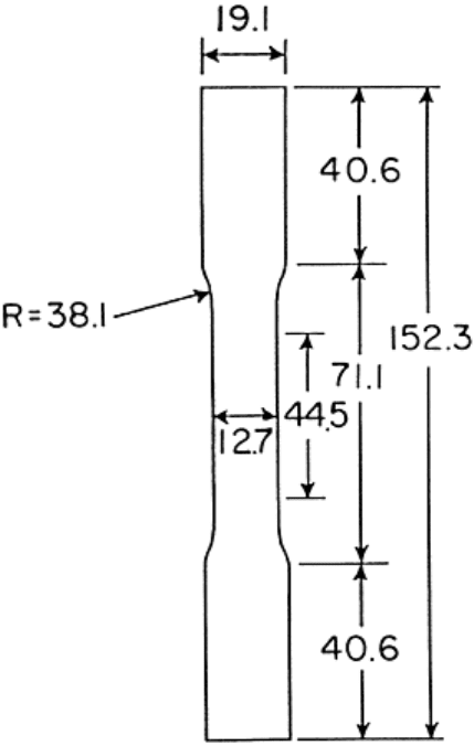
laminates containing 0° fibers required reduction of the gage-section cross-sectional area (as shown in Fig. 5)
so that the specimen would fail in the gage section without slipping or failing in the grips.
Fig. 5 Dog-bone specimen used for tension strength testing of fiber-dominated metal matrix composites.
All dimensions are in millimeters. Source: Ref 16
Test Procedure. Use of standard wedge-action grips with hardened steel serrated jaws is the common practice.
With such grips, the clamping pressure increases in proportion to the axial load acting on the specimen.
Hydraulic grips provide means to adjust the clamping pressure to avoid crushing of the specimen ends at high
loads. Alignment of the test specimen is especially important for unidirectional composites. The specimen is
tested monotonically to failure while recording load, crosshead displacement, and strain. Normally, the test is
run at a crosshead speed of 2 mm/min (0.08 in./min). Failure mode and location should be noted for each test
along with ultimate failure load. A failure located outside the test section justifies rejection of the result. Figure
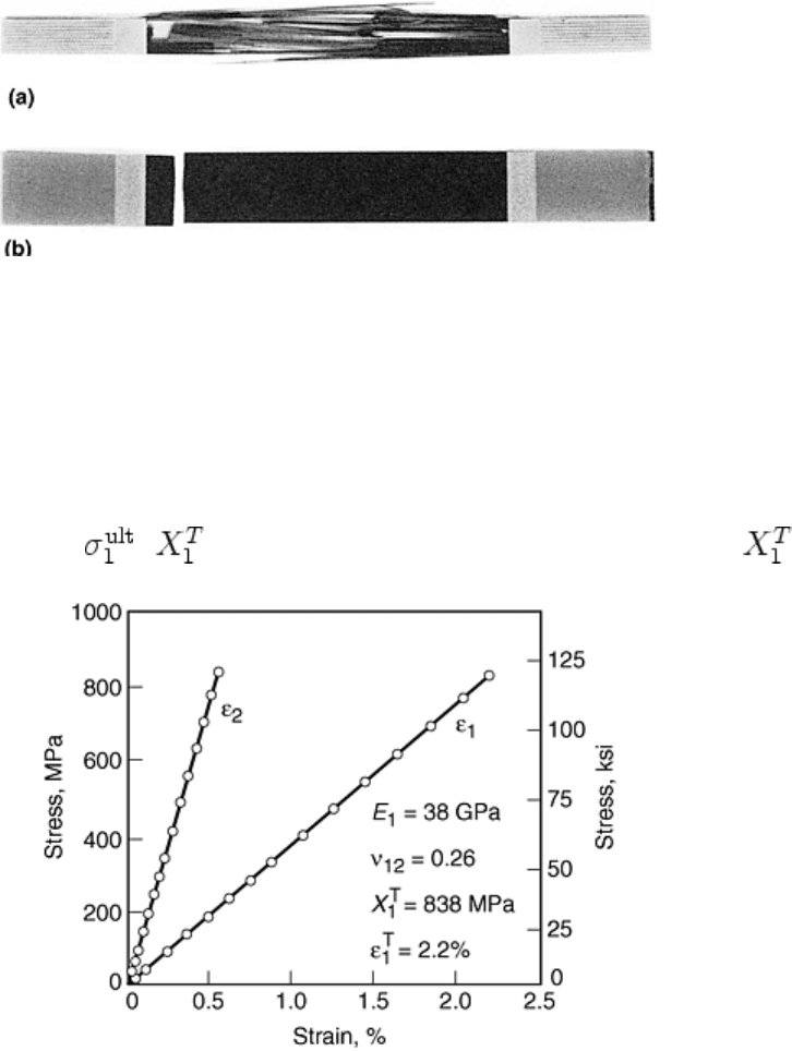
6 shows acceptable and common failure modes for 0 and 90° carbon fiber composites. Some 0° specimens
literally explode. Safety glasses and a protective shield are recommended during tension testing.
Fig. 6 Commonly observed, acceptable failure modes of (a) 0°, and (b) 90° carbon/epoxy unidirectional
composites
Figure 7 shows a representative example of stress-strain curves for a 0° glass/polyphenylene sulfide (PPS)
composite, that is, stress σ
1
versus longitudinal and transverse strains, strains ε
1
and ε
2
. The stress σ
1
is defined
as load divided by cross-sectional area in the test section. Based on the data collected from the test, the modulus
E
1
was reduced using a least squares linear fit to the linear initial portion of the curve σ
1
versus ε
1
. Poisson's
ratio, ν
12
, was determined from the ratio of the initial slopes of σ
1
versus ε
1
and σ
1
versus -ε
2
, with ν
12
= -ε
2
/ε
1
.
The ultimate strength in tension = is the maximum value of σ
1
. Values of E
1
, ν
12
and are given in
Fig. 7.
Fig. 7 Stress-strain response for a unidirectional [0]
8
glass/polyphenylene sulfide (PPS) specimen
Compression Testing
Compression testing is performed by subjecting a test specimen to an increasing compressive load until the
specimen fails in a failure mode that is representative of that in an actual structure. As discussed in Ref 10,
however, compressive failure is triggered by phenomena on the microlevel that are very difficult to observe,
and detailed study is required to reach a clear definition of valid failure modes. It is clear, however, that
strength degradation due to stress concentrations in the specimen arising from load introduction or slight
eccentricities in load-specimen alignment should be minimized and that failure caused by global specimen
buckling must be suppressed. Buckling and kinking of the fibers within the composite are features regarded as
representative for the material and should not be inhibited.
To avoid buckling instability, relatively short gage lengths are necessary, but short gage lengths generally tend
to amplify sensitivities due to clamping. Thus, for very short gage lengths, the apparent compressive strength
tends to decrease (Ref 17, 18, 19). It is likely that nonuniformities in specimen thickness or in the bond or tab
thicknesses result in nonuniform loading in the short gage section, leading to premature failure. Figure 8 shows
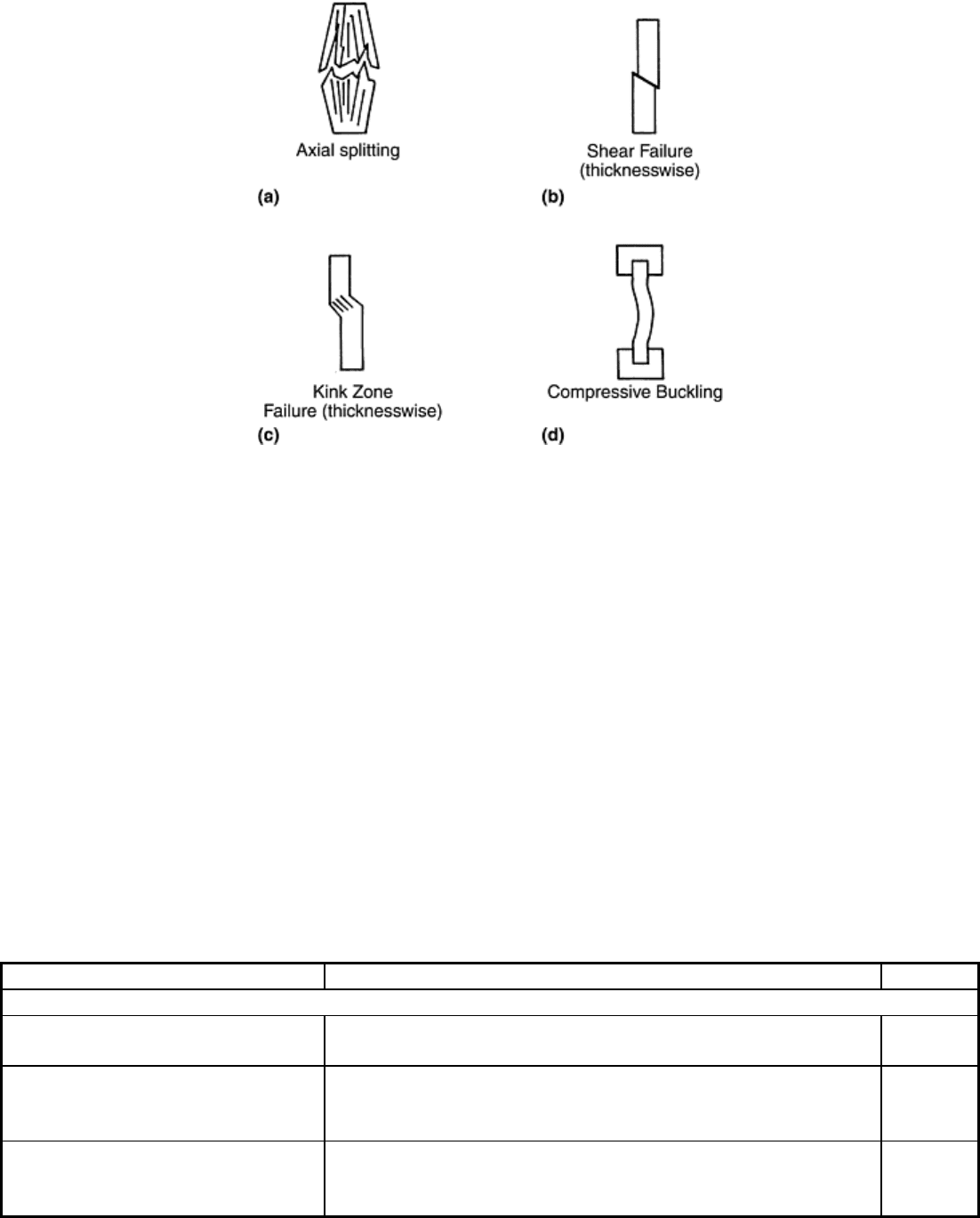
some typical failure modes. The failure modes shown in Fig. 8(a–c) are acceptable, but the column buckling
failure (Fig. 8d) is clearly unacceptable, although difficult to visually observe. Because of the stress
concentration at the tab ends, it is common to observe failure at the tabbed region (Ref 20). Such failures are
not acceptable in tensile testing but are usually accepted in compression testing, because they rarely can be
avoided (Ref 10).
Fig. 8 Typical failure modes for composite compression specimens
Several compression test methods have emerged during the past twenty years, and much confusion exists on
their relative virtues. The methods may be grouped into three categories based on load introduction and
specimen design: shear loading, end-loading, and sandwich beam specimen testing (Fig. 9). The sandwich beam
specimen (Fig. 9c), may be tested in flexure or axial compression. Chatterjee et al. (Ref 10) presented a
thorough review of currently available compression test methods and rated the methods according to problems
associated with load introduction, uniformity of stress field, sensitivity to imperfections, simplicity,
acceptability of failure modes, adequacy of data reduction, specimen preparation and fixture requirements, and
consistency of results. Table 2 summarizes the various test methods and their ratings (1, 2, and 3). The test
methods included in Table 2 are essentially based on polymer matrix composites but should be applicable to
metal matrix and ceramic matrix composites as well. According to Ref 10, the Illinois Institute of Technology
Research Institute (IITRI) test method (ASTM standard D 3410) is the most reliable and versatile. Because of
space limitations, only the methods with the highest rating (1) are described here with the exception of the
Boeing-modified ASTM D 695 method, which has been adopted as a recommended method (SRM 1-88) by the
(Suppliers of Advanced Composite Materials Association) (SACMA). It should be emphasized that while all
the methods provide adequate measures of modulus, the “true” composite strength may not be determined.
Table 2 Compression test methods for fiber-reinforced composites
Method Description Rating
(a)
Shear-loaded specimen test methods
Celanese (ASTM D 3410) Long-established ASTM standard. Results are very sensitive
to accuracy of fixture and test procedure.
2
Wyoming-modified Celanese Cone grips replaced by tapered cylindrical grips. Post and
bearing alignment replaces sleeve. Reduced fixture cost.
Wider specimen
1
IITRI (Illinois Institute of
Technology Research Institute)
(ASTM D 3410)
An ASTM standard since 1987. Tapered flat wedges. Post and
bearing alignment. Massive, relatively expensive fixture.
Wide, thick specimen can be tested.
1
